North Bayou FC35 User manual
FC35
Sit-Stand Workstation Desktop
Instruction Manual
Fits Most Displays Size:22"~32 "
Max Load 6.6~:19.8Ibs (3~9kg)
VESA:75×75,100×100mm
Severe personal injury and property damage can result from improper installation or assembly.
Read the following warning carefully before beginning.
● Products must be installed by professional or installer.
● If you do not understand the instructions or have any concerns or questions, please
contact a qualified local installer.
● Do not install or assemble if the product or hardware is damaged or missing, if you
require replacement parts, please contact you local distributor for assistance.
● This product fits most 22"-32" LCD / monitor; maximum weight of LCD / monitor:
9kg / 19.8lbs.
● Installer-friendly and straight forward.
● For safe installation, the desk you are mounting to must support minimum 3 times the
weight of the total load (the mount, the monitor and all accessories weight).
● Do not use this product for other than the original designed.
● This product contain moving parts, please use with caution.
● When installing monitor, please do not damage electrical wiring or power source.
● Installation and routing of monitor cables on the monitor bracket must comply with
electro-technical regulations.
● Importantly, mains- and data-cables must be secured against twisting and squeezing or
shearing.
● The manufacturer will bear no responsibility to the desk of mounting, or incidental
or consequential damages arising thereof.
● The manufacturer disclaims any liability for the modifications, improper installation, or
installation over the specified weight range. The manufacturer will not be liable for any
damages arising out of the use of , or inability to use, the product.
● This product is designed for indoor used only, use of this product outdoor could lead to
product failer and severe personal injury.
▲ This product contains a high pressure gas spring, fire and percussion are prohibited. Also
it is strictly prohibited to dismantle without professionals. Please return to the manufacturer
or hand over to professional agencies if the product is abandoned. In order to ensure
the performance of gas spring, full direction adjustment of the product arm is recommended
several times per month.
We reserve the right to modify or alter instructions. No modification or alteration without formal notice.
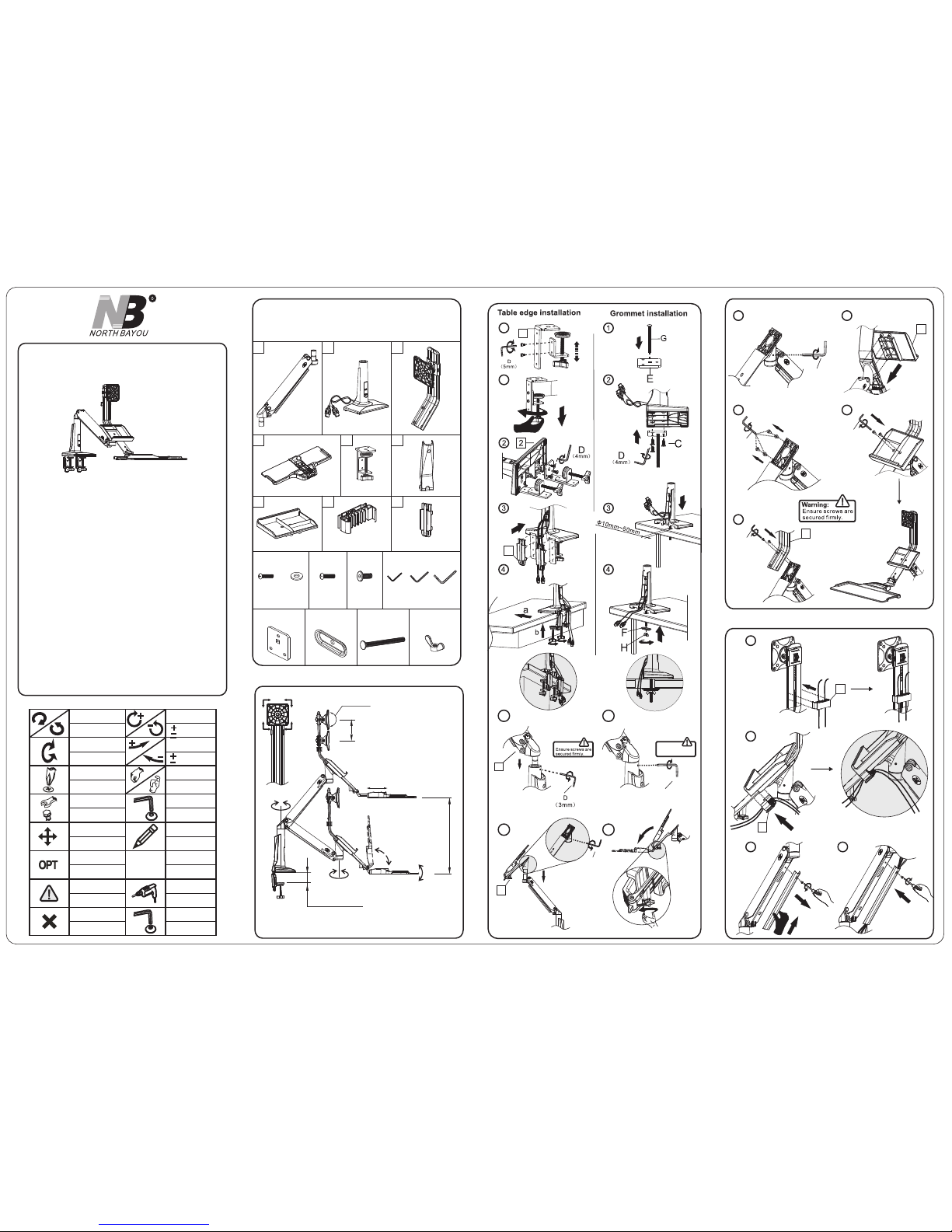
Symbols
Tightening Direction
By Hand
Adjustment
loosen in g Di re ct ion
Hex Wrench
Phillips Screwdriver
Pencil
Optional
Warning
Reminder
Open-End Wrench
Hand Drill
Star Wrench
拧紧方向
用手
调整
拧 方向松
六角扳手
螺丝起子
铅笔
可选
警告
提示
开口扳手
手电钻
安全扳手
Remove
移开
定点恒力加大
定点恒力减小
+
-
:Torque increase d
:Torque reduced
+
-
:Torque increase d
:Torque reduced
拧紧方向
拧 方向松
Tightening Direction
loosen in g Di re ct ion
NOTE
定点恒力加大
定点恒力减小
A、Full adjustment after installation
FC 35
Part List
E GF
2x
1 2 3
46
89
2x
7
(M5x12)
B
4x
A C
6x
(M6x15) (3MM) (4MM) (5MM)
D
H
4001080101 A1
C、Power and display lines installation
1
2
34
a
D
(5mm)
11
9
(5mm)
D
D
(3mm)
10
8
(5mm)
D
3
7
8
8
b
7
(M4x1 2)
4x 4x
(∅10x 4.5 x1.0)∅
360°
FC35 Max Load:6.6~19.8lbs(3~9kg)
0~3.7"(0~95mm)
180°
95°
180°
± °12
0~ 0~3.9"( 100mm)
0~2.4"(0~60mm)
+12°/-15°
0~ 0~18.9"( 480mm)
2x
B、Deskmount installation
Tig hten se t screw
flush w it h sur fa ce.
D
(3mm)
6a
4
5
1a
0-95mm
1b
1
5
9
D
(3mm)
6b
5b
5a
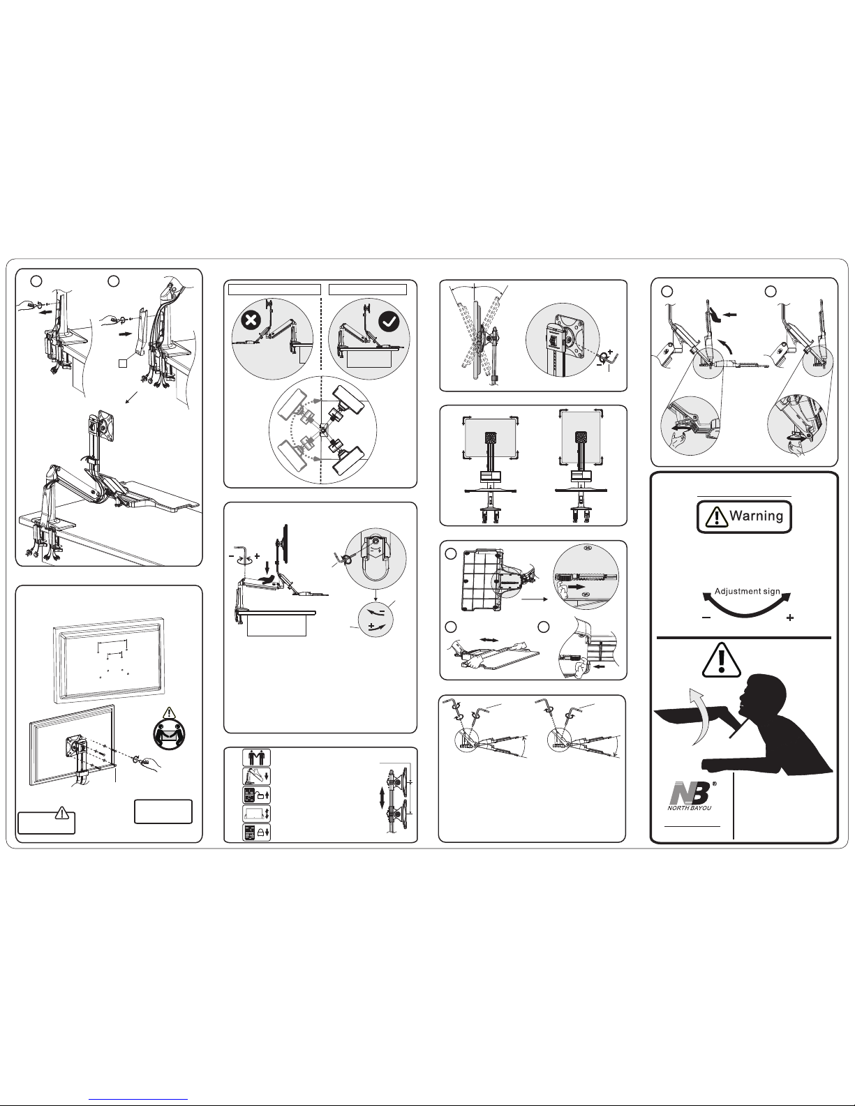
L、Keyboard tray fold up adjustment
ww w.nb av mou nt.co m TEL: 86-512-57971777
FAX: 86-512-57970776
Clockwise t o reduce
tension(c arry less weight)
Anti-cloc kwise to increase
tension(c arry more weight)
Warning!
Add:58, South of Xinxing Road,
Economic Development Zone.
Kunshan City, Jiangsu Province, China.
215333.
Do not adjust tension without putting on display.
1.Ensure display has been put onto mount.
2.Read your display packaging or manual to find
out display net weight.
3.Ensure display net weight between 6.6~19.8lbs
(3~9kg).
TENSION ADJUSTMENT
AFTER INSTALLED
95°
b
1 2
Note:
The pre-sre force is
at the medium.
Warning:
Ensure screws are
secured firmly.
D、Display installation
VESA:75x75mm,100x100mm
75x75mm
100x100mm
6
5
G、Display height adjustment
E、Rotation Restriction
F、Torque adjustment
Non-proper usage directions Proper usage directions
J、Keyboard tray extends adjustment
360°
-15°
+12°
H、Tilt angle adjustment
I、Display rotation
D
( )5mm
K、Keyboard tray angle adjustment
Inclined adjustment Declind adjustment
Declind adjustment:
Inclined adjustment:
①Turn screw anti-clockwise direction using 3mm Allen key D to
release. ②Turn screw clockwise direction using 3mm Allen key
D to tilt upright angle.③Turn screw clockwise direction using
3mm Allen to tighten and secure set angle.
①Turn screw anti-clockwise direction using 3mm Allen key D to
tilt down side angle.②Turn screw clockwise direction using
3mm Allen to tighten and secure set angle.
1
-12°
+12°
①
③②
D
(3mm)
-12°
+12°
D
(3mm)
①
②
0~60mm
2 3
6
a
b
"+ ":Torque increase direction shown fig-1
"- " Torque decrease direction shown fig-2:
fig-1
fig-2
D
( )5mm
Notes:Ensure display weight is within load range.
If display and keyboard tray can be hovered at any height after
display installed. No adjustment needed.
1.
If display and keyboard tray rise up automatically after display
installed, adjust the following: One man hand press down the
screen,the other wind set screw at the bottom of upper arm
at joint to ' – ' direction to reduce torque by using F, 5mm.
Allen key as shown in Fig-1 and Fig-2 until display and keyboard
tray can be hovered at any point of positions.
2.
I f d i s p l a y a n d k e y b o a r d t r a y a t t h e l o w e s t p o s i t i o n a f t e r
installation, repeat #2 procedures but winding set screws to ' + '
direction to increase torque as Fig-1 and Fig-2 until display and
keyboard tray can be hovered at any point of positions.
3.
A/B
Need 2 men. man A and man B.
Once set, man A push kno b down to
lock.
Man A, one han d holds arm down.
Another hand fingers push and hold
knob up to release.
Man B use both hands hold display 2
sides and adjust to desire height.
0~100mm
1.1.
2.
3.
4.
5.
Popular Desktop manuals by other brands

Lenovo
Lenovo THINKCENTRE M710t User guide and hardware maintenance manual

Sony
Sony VAIO Digital Studio PCV-R536DS Specifications

HP
HP dc72 - Blade Workstation Client Deployment guide

Advantech
Advantech USC-130 Series Startup manual

HP
HP Kayak XA-s 02xx manual

NavePoint
NavePoint Open Frame 2 Post Rack quick start guide


