North Shore Safety LineGard Portable Series User manual

Line
Gard
Ground Fault Circuit
NORTH SHORE SAFETY Installation, Testing, and Operating Procedures
40-60 AMP PORTABLE AND PERMANENT SERIES ELCI
7335 Production Drive Mentor, OH 44060 Phone: 440-205-9188 Fax: 440-205-9187 sale[email protected]m www.nssltd.com
IMPORTANT!
Please read all the information on this sheet.
SAVE THESE INSTRUCTIONS!
NOTICE
BEFORE USING READ INSTRUCTIONS COMPLETELY. TO BE
INSTALLED BY A QUALIFIED ELECTRICIAN IN ACCORDANCE
WITH NATIONAL AND LOCAL ELECTRICAL CODES AND THESE
INSTRUCTIONS.
CAUTION!
RISK OF ELECTRIC SHOCK, BURN, OR EXPLOSION.
DISCONNECT POWER BEFORE INSTALLING. NEVER WIRE
ENERGIZED ELECTRICAL COMPONENTS. FAILURE TO DO SO
MAY CAUSE SEVERE SHOCK, PERSONAL INJURY, OR DEATH.
WARNING!
Equipment Leakage Current Interrupter (ELCI) is a
device intended to protect equipment against current
leakage at various levels.
Do not use this ELCI if it fails to function as instructed.
Never attempt to tamper with this device.
This ELCI should never be used as a switch to connect or
disconnect power. (Power should be disconnected at
main power feed or by a secondary switch located at
the primary feed of ELCI).
This ELCI is not an over current protection device. (An
appropriate current breaker should be used in series at
primary power feed)
CAUTION!
Do not use this device to feed power to Life Support
apparatus.
To minimize nuisance tripping: do not use this device on
swimming pool equipment installed prior to 1965 NEC
code, limit load cable to 250 feet and do not use on
electric dryers and ranges with frames grounded by
Neutral conductor.
NOTICE
An ELCI is a device designed to interrupt power when a
ground fault exceeds a predetermined value. The
interruption of power is fast in order to prevent
injuries. The human body is conductive to electricity.
Any electrical apparatus is a potential shock hazard
when used near wet locations.
The ELCI constantly monitors the current balance of the
conductors supplying power to the load. When a
ground fault occurs, by leakage or by shock, the
imbalance of current is sensed and the ELCI trips when
the ground fault exceeds the key selected trip threshold
of the ELCI.
WARNING!
AN ELCI CANNOT DO THE FOLLOWING:
Will not protect line side
Will not protect you when touching two current
carrying conductors of opposite polarity (ELCI
recognizes this as a load)
Will not protect you when touching a line of another
circuit
Will not detect or interrupt overcurrent
NORTH SHORE SAFETY’S TWO-YEAR LIMITED MANUFACTURER’S WARRANTY
North Shore Safety warrants to the consumer its offering of LineGard Ground Fault Circuit Interrupters (GFCIs) to be free from defects in materials
and workmanship under normal use and service for a period of two years from the manufacture date. North Shore Safety, at its option will repair
or replace the defective GFCIs without charge within a two year period from the date of manufacture, provided that the defect occurred during
normal use and was installed according to all published instructions. All returns must be authorized by a North Shore Safety representative. In the
event of product failure please contact a North Shore Safety representative at 1-440-205-9188 to obtain a Return Goods Authorization Number
(RGA) prior to returning any product to North Shore Safety. North Shore Safety will refuse any item if prior Return Goods Authorization has not
been granted. Defective units must be returned prepaid freight, with a description of the problem, and with an attached RGA number referenced
to the Quality Assurance Dept., North Shore Safety, Ltd., 7335 Production Drive, Mentor, OH 44060. Determination of Warranty compliance is
solely at the discretion of North Shore Safety and North Shore Safety's disposition is final.
Disclaimer
North Shore Safety will not be liable, directly or indirectly, for any cost whatsoever associated with installation or removal of any device, or for any
personal injury, property damages, or incidental, indirect, or consequential damages of any kind whatsoever as a result of any defective
device. The exclusive remedy under this Warranty is the repair or replacement of the defective device. In no case shall North Shore Safety's
liability exceed the net purchase price. This Warranty is void if the device is not properly installed, tampered with, opened, abused, or not used
according to label instructions and ratings, and/or published specifications.

Line
Gard
Ground Fault Circuit
NORTH SHORE SAFETY Installation, Testing, and Operating Procedures
40-60 AMP PORTABLE AND PERMANENT SERIES ELCI
7335 Production Drive Mentor, OH 44060 Phone: 440-205-9188 Fax: 440-205-9187 sale[email protected]m www.nssltd.com
SPECIFICATIONS
TECHNICAL:
Rated Voltage: 120VAC, 208VAC, 240VAC, 277VAC, 120/240VAC, 380VAC (custom), 480VAC,
600VAC, 120/208VAC, 277/480VAC, 347/600VAC, 220/380VAC (custom)
Operating Voltage Range: 85% to 110% of rated
Current: 40, 50, 60 Amps
Frequency: 60Hz, 50Hz (available)
Trip Level: 6mA, 10mA, 30mA (selectable)
Phase: Single, Split and Three Phase (3,4, and 5 wire circuits)
Response Time: 25 mS max.
Dielectric Withstand: 1500 VRMS across contact
4000 VRMS between conductors and enclosure
Voltage Surge Withstand: 6000V impulse, 0.5 microsecond rise time, 100KHZ ringing frequency with 40% decay per
cycle
Operating Temperature range: -35°C to +66°C
Leakage Current @ 93% Humidity: Zero
Overload Current: Up to 360 Amps (for 60 Amp), 50% Inductive (240 Amps for 40 Amp, 300 Amps for 50 Amp)
RF Noise Susceptibility: Normal Operation with 0.5 VRMS injected on power line with Frequencies up to 450 MHz.
Let go Line Voltage: 60% of Rated
Grounded Neutral Detection: 2 Ohms or less (on applicable models)
GENERAL:
Construction: Industrial Grade Design
Power –Up Type *: Auto or Manual (selectable)
Endurance: 5000 Operations Minimum
Open Neutral Protection: Trip Upon Loss of Neutral (on applicable models)
Grounded Neutral Protection: Trips if Ground and Neutral touch at load side (on applicable models)
Power ON Indication: Lighted Green LED
Power FAULT Indication: Blinking Red LED, Xenon Strobe on Permanent Series
Enclosure NEMA 4X
Mounting Type: Permanent, and Portable
Wiring Application: 3 Wire, Single Phase (Hot, Neutral, and Ground**)
4 Wire, Single Phase (Line 1, Line 2, Neutral, Ground**)
4 Wire, Three Phase Delta (Line 1, Line 2, Line 3, Ground**)
5 Wire, Three Phase Wye (Line 1, Line 2, Line 3, Neutral, Ground**)
Wiring Connections: Permanent Hardwire (See Type under Model Configuration Chart)
Portable Field Wireable (See Type under Model Configuration Chart)
Switch Interface Double Insulated
Agency Compliance: U.L. and CSA to UL 1053
IMPORTANT NOTE:
* Manual configuration should be specified when automatic power up would create an unsafe condition after restoration of circuit
power.
** Ground connection is done external to device enclosure. (Ground integration is available upon request and is considered a NSS
custom build.)

Line
Gard
Ground Fault Circuit
NORTH SHORE SAFETY Installation, Testing, and Operating Procedures
40-60 AMP PORTABLE AND PERMANENT SERIES ELCI
7335 Production Drive Mentor, OH 44060 Phone: 440-205-9188 Fax: 440-205-9187 sale[email protected]m www.nssltd.com
VOLTAGE (5 WIRES)
(LIMITED TO A 50A MAX)
VOLTAGE (5 WIRES)
VOLTAGE (4 WIRES)
VOLTAGE (3 WIRES)
VOLTAGE (4 WIRES)
VOLTAGE (3 WIRES)
VOLTAGE (3 WIRES)
VOLTAGE (4 WIRES)
PORTABLE
PERMANENT
FIGURE 8
FIGURE 5
FIGURE 3
FIGURE 4
(5 WIRES)** LINE 3 (ORANGE)
LINE 3 (ORANGE)
120/208 VAC
220/380 VAC (CUSTOM)
277/480 VAC
347/600 VAC
(PORTABLE 3Ø WYE)
NEUTRAL (WHITE)
LINE 1 (BLACK)
LINE 2 (RED)
LINE 2 (RED)
LINE 1 (BLACK)
NEUTRAL (WHITE)
LOAD
LINE
FIGURE 1 FIGURE 2
FIGURE 7
FIGURE 6
LOAD
LINE
LOAD
LINE
NEUTRAL (WHITE )
HOT (BLACK)
HOT (BLACK)
NEUTRAL (WHITE)
(3 WIRES)** LOAD
LINE
208 VAC
240 VAC
380 VAC (CUSTOM)
480 VAC
600 VAC
(PERMANENT 1Ø)
L2 (RED)
L1 (BLACK)
L1 (BLACK)
L2 (RED)
(3 WIRES)** LOAD
LINE
LINE 2 (RED)
LINE 1 (BLACK)
LINE 3 OR NEUTRAL (120/240)(WHITE)
LINE 3 OR NEUTRAL (120/240)(WHITE)
LINE 1 (BLACK)
LINE 2 (RED)
(4 WIRES)** LOAD
LINE
LOAD
LINE 2 (RED)
LINE 1 (BLACK)
LINE 3 (YELLOW)
(4 WIRES)** (5 WIRES)**
(4 WIRES)** LINE 2 (RED)
LINE 1 (BLACK)
NEUTRAL (WHITE)
LINE 2 (RED)
LINE 1 (BLACK)
LINE 3 (YELLOW)
LINE
LINE 3 (YELLOW)
LINE 3 (YELLOW)
120/208 VAC
220/380 VAC (CUSTOM)
277/480 VAC
347/600 VAC
(PERMANENT 3Ø)
(WITH NEUTRAL)
NEUTRAL (WHITE)
LINE 1 (BLACK)
LINE 2 (RED)
LINE 2 (RED)
LINE 1 (BLACK)
NEUTRAL (WHITE)
LOAD
LINE
LINE
LOAD
LINE
LOAD (3 WIRES)**
120/240 VAC
(PERMANENT SPLIT Ø)
** GROUND WIRE IS CONNECTED (BYPASSED) EXTERNALLY (FOR PERMANENT MODELS ONLY). A GROUND WIRE DOES NOT ENTER
OR EXIT THE ELCI ENCLOSURE. ALTHOUGH AN ELCI DOES NOT REQUIRE A GROUND TO OPERATE, A GROUND CONNECTION IS
RECOMMENDED AND SHOULD BE MADE AT THE JUNCTION BOX. GROUND WIRE IS CONNECTED IN ALL PORTABLE UNITS.
NEUTRAL OR L2 (WHITE)
HOT OR L1 (BLACK)
HOT OR L1 (BLACK)
NEUTRAL OR L2 (WHITE )
NEUTRAL (WHITE)
LINE 1 (BLACK)
LINE 2 (RED)
120 VAC
208 VAC
240 VAC
277 VAC
480 VAC
600 VAC
(PORTABLE 1Ø)
120/240 VAC
208 VAC
240 VAC
480 VAC
600 VAC
(PORTABLE 3Ø AND SPLITØ)
120 VAC
220 VAC (CUSTOM)
277 VAC
(PERMANENT 1Ø)
208 VAC
240 VAC
380 VAC (CUSTOM)
480 VAC
600 VAC
(PERMANENT 3Ø)
(NO NEUTRAL)
DANGER: HAZARD OF ELECTRICAL SHOCK, BURN, OR EXPLOSION. Disconnect power at main panel before you start the
installation. Failure to do so will cause severe shock, personal injury and death.
IMPORTANT!
1. Read all the instructions in this leaflet and on the device label.
2. Identify all the features and wires (see above drawings).
3. Identify Line wires and Load wires.
4. Verify that the ratings on the device match your field line ratings.
5. Disconnect power at main panel!
6. Determine ELCI location and drill mounting holes using template provided.
7. Strip wires to 5/8”.
8. Feed wires into junction box through appropriate hole and secure cable or
conduit end of ELCI to junction box.
9. Choose the right wiring application and connect wires according to the above
drawings and instructions provided.
10. Secure ELCI box to mounting panel.
11. ELCI may or may not interrupt on phase loss: see ELCI circuit on power-up.
Figure 1: Permanent Series 1200VAC, 220VAC (custom), 277VAC
(single-phase, 3-wire)
Connect field service (Hot) to ELCI line side (Hot - black wire) utilizing an
appropriate rated wire connector.
Connect field service (Neutral) to ELCI line side (Neutral –white wire) utilizing
an appropriate rated wire connector.
Connect device or circuit load (Hot) to ELCI load side (Hot –black wire)
utilizing an appropriate rated wire connector.
Connect device or circuit load (Neutral) to ELCI load side (Neutral –white wire)
utilizing an appropriate rated wire connector.
Connect field service safety ground to load side device or equipment grounding
point. “Safety ground does not enter or exit ELCI and is bypassed.”
NOTE: ELCI circuitry is powered by (Hot and Neutral) and thus circuit must be
maintained for ELCI to operate.
Figure 2: Permanent Series 120/240VAC (split-phase, 3-wire)
Connect field service (Hot/L1) to ELCI line side (Hot/L1 - black wire) utilizing
an appropriate rated wire connector.
Connect field service (Hot/L2) to ELCI line side (Hot/L2 - red wire) utilizing an
appropriate rated wire connector.
Connect field service (Neutral) to ELCI line side (Neutral –white wire) utilizing
an appropriate rated wire connector.
Connect device or circuit load (Hot/L1) to ELCI load side (Hot/L1 –black wire)
utilizing an appropriate rated wire connector.
Connect device or circuit load (Hot/L2) to ELCI load side (Hot/L2 –red wire)
utilizing an appropriate rated wire connector.
Connect device or circuit load (Neutral) to ELCI load side (Neutral –white wire)
utilizing an appropriate rated wire connector.
Connect field service safety ground to load side device or equipment grounding
point. “Safety ground does not enter or exit ELCI and is bypassed.”
NOTE: ELCI circuitry is powered by (L1 and Neutral) and thus circuit must be
maintained for ELCI to operate.
Figure 3: Permanent Series 208VAC, 240VAC, 480VAC, 600VAC
(single-phase, 3-wire)
Connect field service (Hot/L1) to ELCI line side (Hot/L1 - black wire) utilizing
an appropriate rated wire connector.
Connect field service (Hot/L2) to ELCI line side (Hot/L2 - red wire) utilizing an
appropriate rated wire connector.
Connect device or circuit load (Hot/L1) to ELCI load side (Hot/L1 –black wire)
utilizing an appropriate rated wire connector.
Connect device or circuit load (Hot/L2) to ELCI load side (Hot/L2 –red wire)
utilizing an appropriate rated wire connector.
Connect field service safety ground to load side device or equipment grounding
point. “Safety ground does not enter or exit ELCI and is bypassed.”
NOTE: ELCI circuitry is powered by (L1 and L2) and thus circuit must be
maintained for ELCI to operate.
Line
Gard
Ground Fault Circuit
NORTH SHORE SAFETY Installation, Testing, and Operating Procedures
40-60 AMP PORTABLE AND PERMANENT SERIES ELCI
7335 Production Drive Mentor, OH 44060 Phone: 440-205-9188 Fax: 440-205-9187 sale[email protected]m www.nssltd.com
TESTING AND TROUBLESHOOTING
1. Restore the power to the ELCI (power switch to on position).
2. Press and release RESET button, Green Light (Power) should turn ON (Auto Reset will
automatically come on).
3. Press Test Button. Green Light (Power) turns off and Red Blinking Light (Fault) turns on.
4. Press and Release the RESET button. Red Light (Fault) turns OFF and Green Light (Power)
turns ON.
5. CHECKING FOR CORRECT WIRING:
If ELCI is wired to protect equipment, press and release RESET button. Verify that equipment
power is on. Press TEST button. Equipment power should turn off. If equipment power does
not come on when pressing and releasing RESET button, or if power stays on when pressing
TEST button, turn main power off, check and correct your wiring connections. Repeat steps 1-
4. If problem persists, do not use this ELCI. Consult a qualified electrician for assistance or
replacement.
SET UP
Turn “Reset Setting” to “auto” position to power ELCI with each restoration event of
primary (supply) power, Green Light (Power) turns on.
Turn “Reset Setting” to “MAN” (manual) position for safe start power up of ELCI. This
setting requires the resetting of the ELCI manually with each restoration event of
primary (supply) power, Red Blinking Light (Fault) turns on.
CAUTION: Where unanticipated power restoration could pose a safety risk due
to accidental power-ups, a manual reset setting should be key selected.
NOTE: Both reset types require resetting after a ground fault occurrence.
TRIP LEVEL SETTING
Turn “Trip Level Setting” to desired trip level threshold. This represents the fault
leakage response level of the ELCI.
CAUTION: The lowest trip level threshold without the inducement of nuisance
tripping should be selected; this will provide the greatest level of personnel
protection.
NOTE: This device as rated is not a personnel protection device but offers a
significant level of human protection over a non-protected circuit.
POWER SWITCH SETTINGS
Turn “Power Switch” to “ON” position to initiate power to ELCI, Green Light (Power) or
Red Light (Fault) should turn on.
Turn “Power Switch” to “OFF” position to disconnect power to ELCI, Green Light
(Power) or Red Light (Fault) should turn off.
CAUTION: The power switch should not be used as a main power disconnect
switch. Power should be disconnected at main service panel prior to service
work. Unit has live internal components even when in power off position.
NOTE: The power switch in the off position terminates all fault indications.
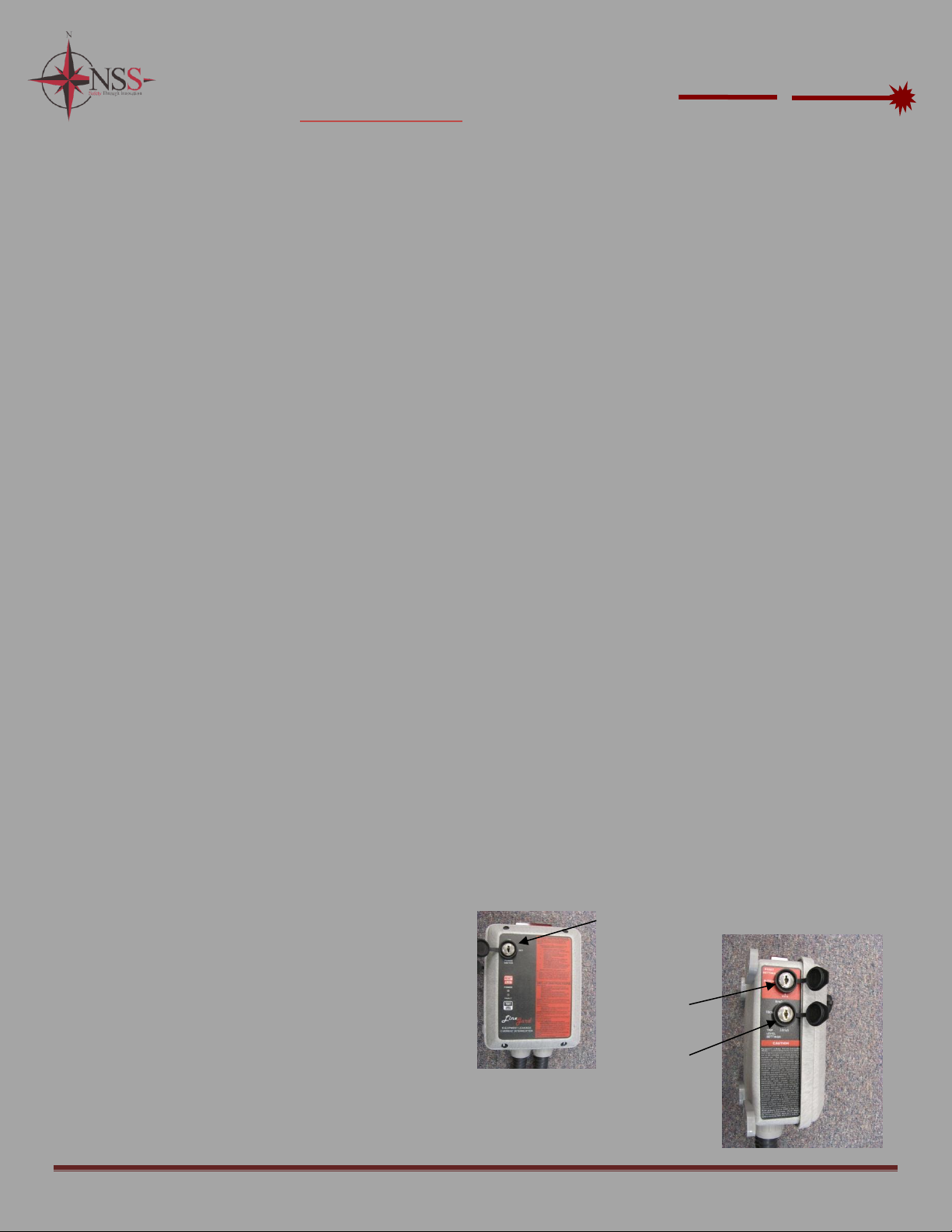
(Key Switch)
Power Lock
Out
Key Switch
(Auto / Manual Reset)
Key Switch
(mA Trip Setting)
(6, 10, 30)
Figure 4: Permanent Series 208Vac, 240VAC, 380VAC (custom), 480VAC, 600VAC
(three-phase, 4-wire)
Connect field service (Hot/L1) to ELCI line side (Hot/L1 - black wire) utilizing
an appropriate rated wire connector.
Connect field service (Hot/L2) to ELCI line side (Hot/L2 - red wire) utilizing an
appropriate rated wire connector.
Connect field service (Hot/L3) to ELCI line side (Hot/L3 –yellow wire) utilizing
an appropriate rated wire connector.
Connect device or circuit load (Hot/L1) to ELCI load side (Hot/L1 –black wire)
utilizing an appropriate rated wire connector.
Connect device or circuit load (Hot/L2) to ELCI load side (Hot/L2 –red wire)
utilizing an appropriate rated wire connector.
Connect device or circuit load (Hot/L3) to ELCI load side (Hot/L3 –yellow wire)
utilizing an appropriate rated wire connector.
Connect field service safety ground to load side device or equipment grounding
point. “Safety ground does not enter or exit ELCI and is bypassed.”
NOTE: ELCI circuitry is powered by (L1 and L2) and thus circuit must be
maintained for ELCI to operate.
Figure 5: Permanent Series 120/208VAC, 220/380VAC (custom), 277/480VAC,
347/600VAC (three-phase, 5-wire)
Connect field service (Hot/L1) to ELCI line side (Hot/L1 - black wire) utilizing
an appropriate rated wire connector.
Connect field service (Hot/L2) to ELCI line side (Hot/L2 - red wire) utilizing an
appropriate rated wire connector.
Connect field service (Hot/L3) to ELCI line side (Hot/L3 –yellow wire) utilizing
an appropriate rated wire connector.
Connect field service (Neutral) to ELCI line side (Neutral–white wire) utilizing
an appropriate rated wire connector.
Connect device or circuit load (Hot/L1) to ELCI load side (Hot/L1 –black wire)
utilizing an appropriate rated wire connector.
Connect device or circuit load (Hot/L2) to ELCI load side (Hot/L2 –red wire)
utilizing an appropriate rated wire connector.
Connect device or circuit load (Hot/L3) to ELCI load side (Hot/L3 –yellow wire)
utilizing an appropriate rated wire connector.
Connect device or circuit load (Neutral) to ELCI load side (Neutral –white wire)
utilizing an appropriate rated wire connector.
Connect field service safety ground to load side device or equipment grounding
point. “Safety ground does not enter or exit ELCI and is bypassed.”
NOTE: ELCI circuitry is powered by (L1 and L2 on 277/480VAC and
347/600VAC Circuits) and thus circuit must be maintained for ELCI to operate.
Exception: 120/208VAC and 220/380VAC are powered by (L1 and Neutral).
Figure 6: Portable Series 120VAC, 208VAC, 240VAC, 277VAC, 480VAC,
600VAC (single-phase, 3-wire)
Connect field service (Hot/L1) to ELCI line side (Hot/L1 - black wire) utilizing
an appropriate rated wire connector.
Connect field service (Neutral/L2) to ELCI line side (Neutral/L2 - white wire)
utilizing an appropriate rated wire connector.
Connect field service (Safety Ground) to ELCI line side (Safety Ground –green
wire) utilizing an appropriate rated wire connector.
Connect device or circuit load (Hot/L1) to ELCI load side (Hot/L1 –black wire)
utilizing an appropriate rated wire connector.
Connect device or circuit load (Neutral/L2) to ELCI load side (Neutral/L2 –
white wire) utilizing an appropriate rated wire connector.
Connect device or circuit load (Safety Ground) to ELCI load side (Safety Ground
–green wire) utilizing an appropriate rated wire connector.
NOTE: ELCI circuitry is powered by (L1 and N/L2) and thus circuit must be
maintained for ELCI to operate. White wire is Neutral for 120VAC and 277VAC
circuits.
Figure 7: Portable Series 120/240VAC, 208VAC, 240VAC, 480VAC, 600VAC (split
and three-phase, 4-wire)
Connect field service (Hot/L1) to ELCI line side (Hot/L1 - black wire).
Connect field service (Hot/L2) to ELCI line side (Hot/L2 - red wire).
Connect field service (Neutral or L3) to ELCI line side (Neutral or L3 –white
wire) (Neutral for 120/240VAC).
Connect field service (Safety Ground) to ELCI line side (Safety Ground–green
wire).
Connect device or circuit load (Hot/L1) to ELCI load side (Hot/L1 –black wire).
Connect device or circuit load (Hot/L2) to ELCI load side (Hot/L2 –red wire).
Connect device or circuit load (Neutral or L3) to ELCI load side (Neutral or L3 –
white wire) (Neutral for 120/240VAC).
Connect device or circuit load (Safety Ground) to ELCI load side (Safety Ground
–green wire).
NOTE: ELCI circuitry is powered by (L1 and L2) and thus circuit must be
maintained for ELCI to operate. Exception: Split phase is powered by (L1 and
Neutral).
Figure 8: Portable Series 120/208VAC, 220/380VAC (custom), 347/600VAC,
277/480VAC (three-phase WYE, 5-wire)
Connect field service (Hot/L1) to ELCI line side (Hot/L1 - black wire).
Connect field service (Hot/L2) to ELCI line side (Hot/L2 - red wire).
Connect field service (Hot/L3) to ELCI line side (Hot/L3 –orange wire).
Connect field service (Neutral) to ELCI line side (Neutral –white wire).
Connect field service (Safety Ground) to ELCI line side (Safety Ground–green
wire).
Connect device or circuit load (Hot/L1) to ELCI load side (Hot/L1 –black wire).
Connect device or circuit load (Hot/L2) to ELCI load side (Hot/L2 –red wire).
Connect device or circuit load (Hot/L3) to ELCI load side (Hot/L3 –orange wire).
Connect device or circuit load (Neutral) to ELCI load side (Neutral –white wire).
Connect device or circuit load (Safety Ground) to ELCI load side (Safety Ground –
green wire).
NOTE: ELCI circuitry is powered by (L1 and L2 on 220/380VAC, 277/480VAC,
and 347/600VAC) and thus circuit must be maintained for ELCI to operate.
Exception: 120/208VAC is powered by (L1 and Neutral).

Line
Gard
Ground Fault Circuit
NORTH SHORE SAFETY Installation, Testing, and Operating Procedures
40-60 AMP PORTABLE AND PERMANENT SERIES ELCI
7335 Production Drive Mentor, OH 44060 Phone: 440-205-9188 Fax: 440-205-9187 sales@nssltd.com www.nssltd.com
MOUNTING HOLES
7.39”H x 7.47”W
INSTALLATION TEMPLATE
(actual size)
This manual suits for next models
1
Table of contents
Popular Portable Generator manuals by other brands


Keysight Technologies
Keysight Technologies E8257D Service guide

Poulan Pro
Poulan Pro PPG 6000 owner's manual

Hyundai
Hyundai HPS-300 user manual

Contractor Line
Contractor Line GEN8000 instruction manual

Generac Power Systems
Generac Power Systems CorePower Repair manual

Powermate
Powermate PM0545010 user manual


