NORTHERN ELECTRIC QSE4A Instruction Manual
TCI Library- http://www.telephonecollectors.info/
NORTHERN ELECTRIC
CO.
LTD.
MONTREAL, CANADA NORTHERN ELECTRIC PROCEDURES
9006Q-103
ISSUE 1
JANUARY, 1972
QSE4A AND QSE4B TYPE HANDSETS
(DIAL HAND TEST SET)
DESCRIPTION, OPERATION AND MAINTENANCE
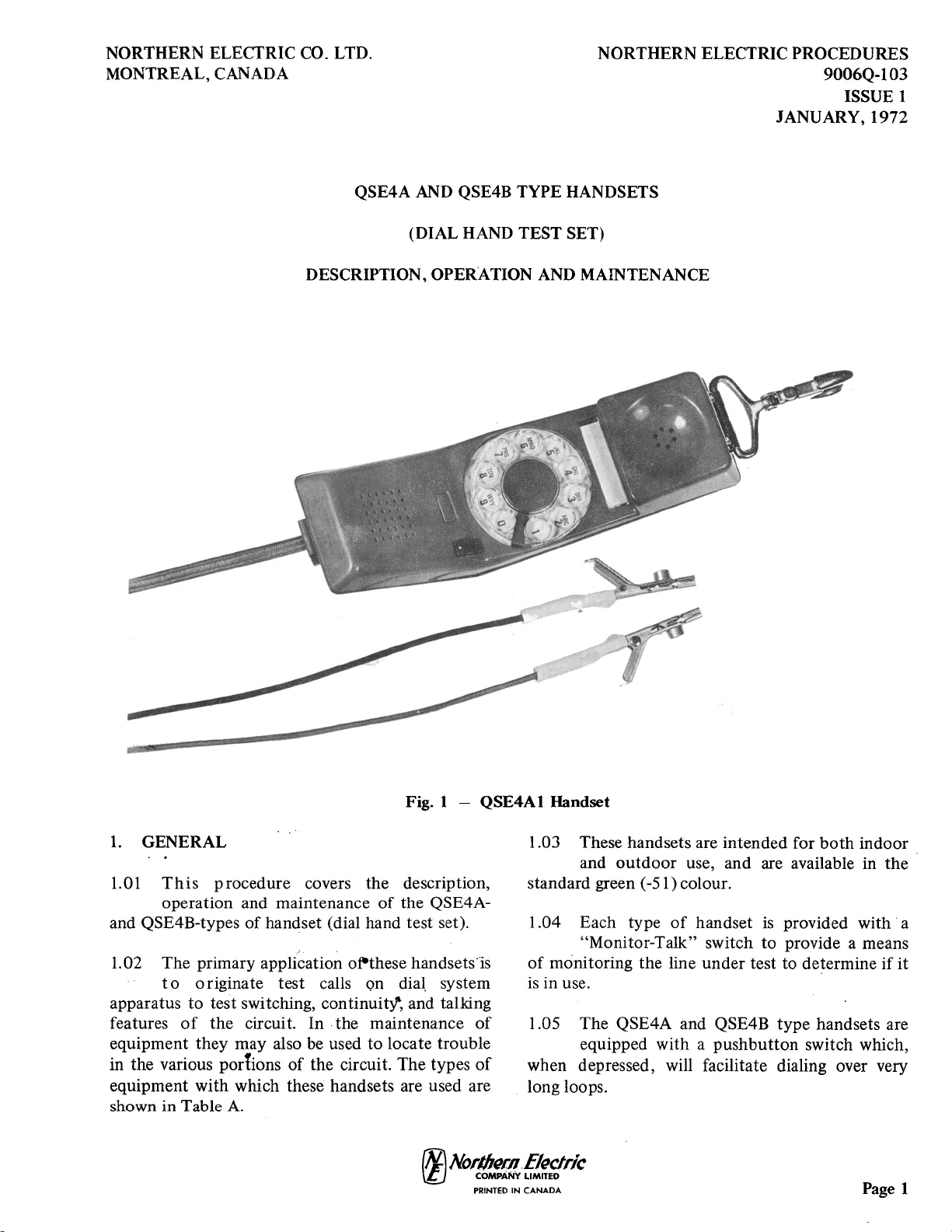
Fig. 1 -QSE4A1 Handset
1.
GENERAL
1.01
This
procedure
covers the description,
operation and maintenance
of
the QSE4A-
and QSE4B-types
of
handset (dial hand test set).
1.02 The primary application of-these handsets·is
to
originate test calls on
dial.
system
apparatus
to
test switching, continuity'; and talking
features
of
the circuit. In the maintenance
of
equipment they may also be used
to
locate trouble
in the various por1ions
of
the circuit. The types
of
equipment with which these handsets are used are
shown
in
Table
A.
I
.OJ
These handsets are intended for
both
indoor
and
outdoor
use, and are available in
the
standard green (-51) colour.
1.04 Each type
of
handset
is
provided
with·
a
"Monitor-Talk" switch to provide a means
of
monitoring the line
under
test to determine
if
it
is
in use.
1.05
The
QSE4A and QSE4B
type
handsets are
equipped with a
pushbutton
switch which,
when depressed, will facilitate dialing over very
long loops.
rNJ
Norl/J«n.Elt1clrlc
(lj
COMPANY LIMITED
PRINTED
IN
CANADA
Page
1
TCI Library- http://www.telephonecollectors.info/
9006Q-103
TABLE
"A"
Identification Primary Cord
Handset Dial Center App
Ii-
Cord Termina- See
Code Insert Features cation Code tion Note
QSE4Al
Red Medium Impedance
Monitor Outside NE- Test
QSE4Bl
Yellow High Impedance Plant
W2QK
Clips
Data -Manual NSQ4100-
Return-to-Monitor
LI
QSE4A2 Red Medium Impedance
Monitor
General NE- NE-346A
I
QSE4B2 Yellow High Impdenace Use
H2QB
Plug
Data -Manual
Return-to-Monitor
NOTE
I: QSE4A2 and QSE4B2 handsets provide an arrangement whereby a basic coded handset can be
adapted,
by
means
of
plug-in cords,
to
all Central Office tests requiring
the
use
of
a handset.
1.06
If
these handsets are accidentally connected
directly
across
48
volts
with
the
"Monitor-Talk"
switch in
the
talk position,
the
circuit design
is
such
that
minimum damage results.
1.07 Conversion Parts: Parts are available to
modify
QSE4A
type
handsets in service
to
QSE4B types, in
order
to
provide
the
additional
features shown in Table
B.
For
installation
of
these
conversion kits, refer to
4.10.
NOTE:
When this condition occurs, the
QHP99A
inductor
located
on
PC2
(P0500416
or
P05004
l
7)
is
subjected
to
excessive power
dissipation for approximately
10
seconds, at
which time the
thermistor
limits the current
to
a safe level.
CONVERT
FROM
QSE4A- Medium Impedance
Monitor (Non-Data)
Page
2
TABLE B
CONVERT
TO
QSE4B- High Impedance
Monitor Manual (Data-Manual)
rN:i
Northern
Electric
rtJ
COMPANY
LIMITED
PRINTED
IN
CANADA
PART NUMBER
P0500416
TCI Library- http://www.telephonecollectors.info/
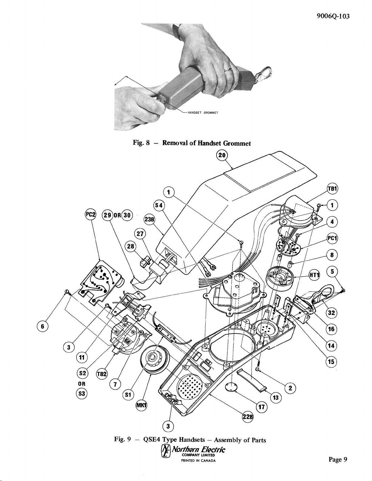
1.08 Identification and assembly
of
parts
is
shown in Fig. 9 and Table
C.
2.
DESCRIPTION
2.01 The
QSE4Al
and QSE4B1 type Handsets
consist
of
a plastic handset equipped
with
an
NE-1
0QA
type
Dial in
the
center
of
the
housing, an NE-Tl Transmitter Unit,
an
NE-Ul
Receiver Unit, and a cord provided with test clips
(see Fig. 1).
2.02 The
QSE4Al
and QSE4B1 handsets differ
in
their
operational features and circuitry,
as
shown in Table A and Fig. 3 and 4.
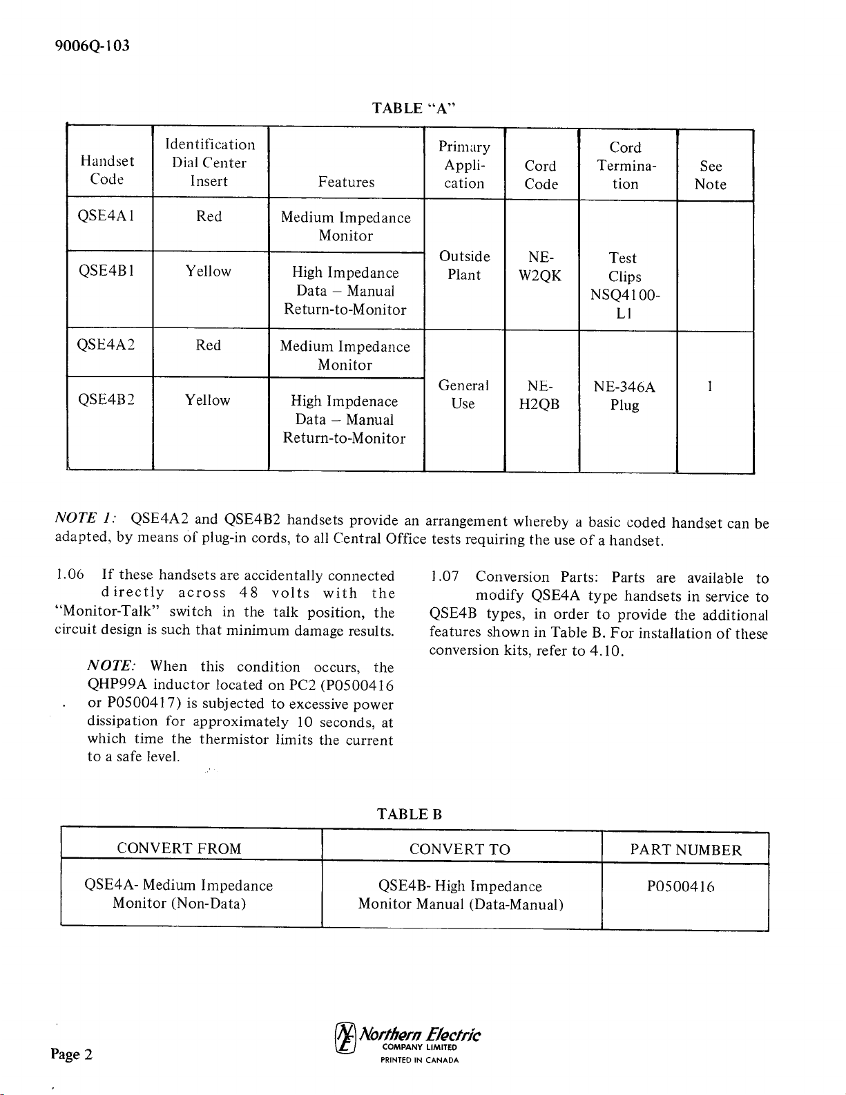
2.03 The QSE4A2 and QSE4B2 Handsets are
the
same
as
the
QSE4Al
and QSE4B1 types
respectively, except
that
they use a cord equipped
with
an
NE-346A plug. This plug-ended cord
provides an arrangement whereby a basic coded
handset can be adapted,
by
means
of
plug-in cords,
to
all Central Office tests requiring the use
of
a
handset (Fig. 2).
2.04 The QSE4A
type
Handsets are for use
where
data
transmission facilities are
not
provided, and it
is
only necessary
to
bridge
the
line
under
test
with
a medium impedance
of
I
000
ohms in
the
"Monitor"
position,
as
indicated
on
the
rocker switch when
the
red face is hidden. In
the
"Talk"
position the red face
on
the
switch
is
visible and
the
de resistance
is
approximately 130
ohms. The use
of
the
pushbutton
is described in
3.01 (4).
2.05 The QSE4B Handsets are designed for use in
areas
where
local plant involves
data
circuits, and
it
is
essential
to
monitor
lines before
test
with
a high impedance bridging
the
line. This
high impedance
is
approximately 100,000
ohms
in
the
"Monitor"
position and will
not
disrupt
data
transmission which may
be
underway.
The
change
from
"Monitor"
to
"Talk"
is accomplished
by
a
rocker switch,
after
ensuring
that
the
line is
not
in
use. This switch
must
be in
the
"Monitor"
position
before using
the
handset
to
test the line.
The
use
of
the
pushbutton
switch is described
in
3.02
(4i
r1liNortlN!m
E/edrlc
rt.)
COMMNYUMITED
PRINTED
IN
CANADA
9006Q-103
Fig. 2 - QSE4B2 Handset

TCI Library- http://www.telephonecollectors.info/
z
(1)
~
~
~
n;\
~~
-:
""
~~
~~
~~
~
t=i·
PC2
RD
T
RD
I
Cl
11
2UF
LI
BK
SL
SJ
BL
I
BL
BL
i I
I
I
I
I
!
i I:
SL-WH
I I I
GN
l
RD-SL
S4
Fig. 3
WH
YEL-SL
TB2
YEL-SL
~
I
BL
I J
OR
It
_£
1 ))
~~
CORD
BL
RD
BL
BL
PC!
BL
RI
68\1
MK!
RV!!
l
Cl
C2
I
4UF
4UF
YEL-SL
I .
I(~.
YEL-SL
I
WH
I
TPI
HT!
__
SL
401!
~
t
SJ
SL-BR
QSE4A Handset Schematic and Wiring
-a
0
0
0-
t?
-
0
(;.J

TCI Library- http://www.telephonecollectors.info/
~
~
;ss
~
3:~
0
i~\,J
-Z~
z -<""
n r-t,,
►
-
z
3:
::s
~
;:~
>
o;;_
~
.,,
t.)
(:,Q
I'!>
J•
,s,
RD
BK
YEL-SL
Tl
Cl
.
0022UF
Tl
PR!
PCZ
RD
OR
Fig. 4
BL
OR
NOTE
I
YEL-SL
----,
I
BL
L
SL-WH
BL
•
f
SL-RO
sz
RD-SL
•
SL-BR
WH
WH
YEL-S_L._
SL-RD
BL
RO]
CORO
' I
BK
..L----:f:i~;r,,,-
BL
PC!
68"
RV!
Cl
CZ
YEL-SL
L
..
4Uf
4UF
1
• I
YEL-SL
I
E--)1
+
I ,
SL
TPI
40u
A
QSE4B Handset
Schem:itk
and Wiring
C
MK!
HTl
'°
0
0
0'
0
I
0
(.,..,

TCI Library- http://www.telephonecollectors.info/
9006Q-103
Page 6
NE-471A
JACK
NE-W2DB
CORD
N
E-47
lA
JACK
NE-W2CK
CORD
NE-471A
JACK
--
NE-W2CL
CORD
N
E-47
lA
JACK
NE-W2CL
CORD
NE-471A
JACK
NE-W2CJ
CORD
WHEN
NE-471A
JACK
NS-8010
SWITCH
CONTACT CLOSED
"ON"
IS
DEPR
ESSE
CONTACT OPEN
WH
"OFF"
IS
DEPRESS
D.
EH
ED.
N
E-471A
JACK
NE-W3AH
CORD
NE-471 A JACK
NE-W4AY
CORD
A
.
.
.
.
.
.
-
---
-
'--
'--
1
-
~
I
-
'--
j_
'--
.-----
NS-6780 CONNECTING CLIP
NE-2W37A
CORD
---
NE-108
CORD
TIP
NE-2W38A
CORD
V
♦
'
12000
•
NE-2W39A
CORD
V •
-
o-r
NE-310
PLUG
I
,--
1-
--
NE-240A
PLUG
-l
.--
1200
0
_r7
I _
--
-
NE-2W40A
CORD
NE-240H
PLUG
NE-360A
T
'
I,
NE-3608
T
· NE-2W41A
CORD
2000
0
-
"
♦
I·
,.......J
I,
0-
--
I • -
NE-3W8A
CORD
+
2000
0
rt
~
'
',.-1:
'
~
,
f"lc
·~
NE-3W10A
CORD
,-
t
I t
I L
V -
NE-240A
PLUG
NE-4W10A
CORD
OOL
OOL
NE-W3AA
CORD
NS-6780 CONNECTING
CLIP
NE-108
CORD
TIP
•TOOLS
SUCH
AS
THE
NE-411A
TOOL MAY BE
USED
WITH
THE
NE-2W4lA
CORD
BY
INSERTING THEM
IN
THE
NE-360-TYPE
TOOLS
Fig. 5 -
Schematics
of
Accessory Cords
for
QSE4A2
and
QSE4B2 Handsets
rM
Northern
Electric
'{t_j
COMPANY
LIMITED
PRINTED
IN
CANADA
TCI Library- http://www.telephonecollectors.info/
9006Q-103
2.06 Equipment features
of
the different types
of
handsets are shown in Table A.
2.07
Schematic
and wiring diagrams
of
the
handsets are shown in Figs. 3 and 4.
2.08 Fig. 5 shows the schematic diagrams
of
the
accessory cords available for use
with
the
QSE4A2 and QSE4B2 Handsets.
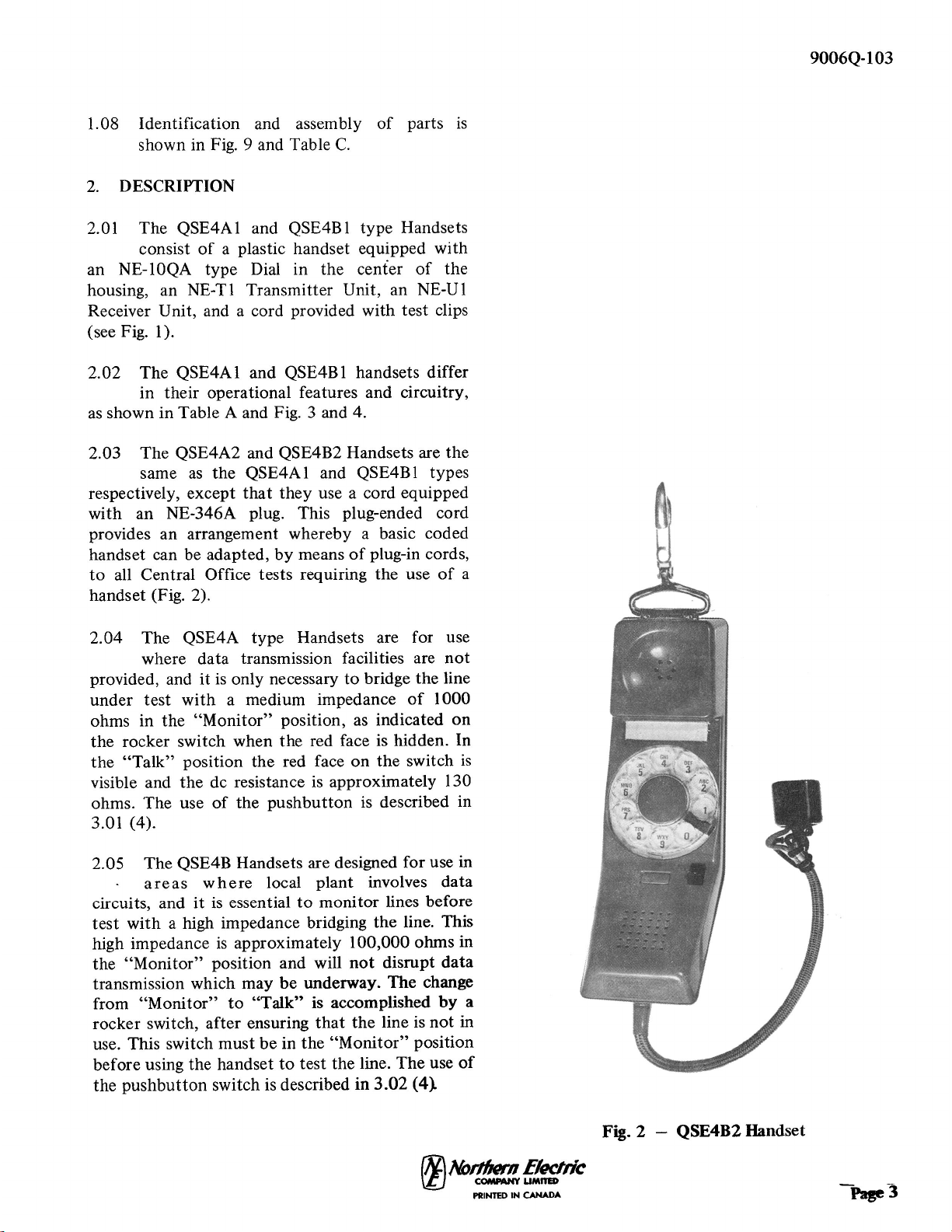
2.09 All handsets are equipped with a snap
hook
to
allow the handset to be carried
on
a tool
belt. The
hook
is
positioned in such a manner
as
to
allow the handset to hang and follow the
contour
of
the
body
, thus affording protection
to
the face
of
the handset
as
shown in Fig.
6.
2.10 When
the
handset is
not
in use, the cord
should be wrapped
as
shown in Fig. 7.
3. OPERATIONAL
PROCEDURE
3.01 QSE4A Type Handsets:
9006Q-103
(1)
.Make certain
that
the test clips
make
electrical contact with
only
one circuit
at
a
time.
Fig. 6 -Wearing
of
Handset
on
Tool
Belts
(2)
To
bridge the line
under
test,
the
rocker
switch should be in the
"Monitor"
position,
which
is
indicated by the red face
of
the switch
being hidden. In this mode, the handset has an
impedance
of
approximately 1000 ohms.
(3)
Dialing can be accomplished in
the
normal
manner,
however,
since
the handset
resistance
is
slightly higher
than
the resistance
of
an NE-500 type Telephone Set, difficulty could
be encountered
when
dialing over a very
long
line.
(4)
If
dialing difficulty
is
experienced, it can be
overcome
by
keeping the
pushbutton
depressed while dialing. This procedure allows
the handset
to
operate
on
any line which
permits operation
of
an NE-500
type
Telephone
Set.
Fig. 7 -Method
of
Wrapping Cord
When Handset is
Not
in Use
(10.
Northern
Electric
'\l_}
COMPANY LIMITED
PRINTED
IN
CANADA Page 7
TCI Library- http://www.telephonecollectors.info/
9006Q-103
(5) If talking
is
necessary, the
rocker
switch
must be placed in the
"Talk"
position,
whid1
is
indicated by the red face
of
the switch
being visible. to establish the talking circuit.
(6) Checking for the presence
of
48
volts on the
line should be
done
with the
rocker
switch
in the
"Talk"
position (red face showing). Clicks
will be produced in
the
receiver each time
48
volts
is
present on the test clips.
3.02 QSE4B
Type
Handsets:
(
1)
Make certain
that
the test clips make
electrical
contact
with
only one circuit at a
time.
(2)
To
bridge the line
under
test,
the rocker
switch should be
in
the
"Monitor"
position,
which
is
indicated by the red face
of
the·switch
being hidden. In this mode, the
handset
presents
a very high impedance
to
the line, which ensures
minimum loading
of
the line
under
test and thus
can be used
on
circuits where data
is
present.
(3)
If
talking
is
necessary, the rocker switch
must
be placed in the
"talk"
position, which
is
indicated
by
the red face
of
the switch being
visible,
to
establish the talking circuit.
(
4)
Dialing can be accomplished in
the
normal
manner,
however,
since
the handset
resistance
is
slightly higher
than
the
resistance
of
an NE-500
type
Telephone Set, difficulty could
be
encountered
when dialing over very long
lines. This dialing difficulty can be overcome by
keeping the
pushbutton
depressed while dialing.
(5) Checking for the preseni.:e
of
48 volts on the
line should be
done
with the rocker switch
in
the
"Talk"
position (red face showing). Clicks
will be produced
in
the receiver each
time
48
volts
is
present on the test clips.
4.
MAINTENANCE
4.01
Normal
maintenance
may
involve
replacement
of
the dial.
transmitter
unit,
receiver unit, or the cord.
NOTE: Dial maintenance consists only
of
determining if
the
dial
is
defective. Do not
attempt
adjustments
of
the
dial
in
the
field.
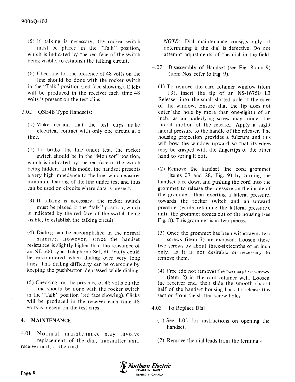
4.02 Disassembly
of
Handset (see Fig. 8
and
9)
(item Nos. refer to Fig. 9).
(
1)
To
remove
the
card retainer window
(item
13), insert
the
tip
of
an NS-16750
L3
Releaser
into
the
small slotted hole
at
the edge
of
the window. Ensure
that
the
tip does
not
enter
the
hole
by
more
than
one-eighth
of
an
inch,
as
an underlying screw may hinder the
lateral
motion
of
the releaser. Apply a slight
lateral pressure
to
the handle
of
the
releaser. The
housing projection provides a fulcrum and
thi,
will bow
the
window upward so
that
its edge-.
may be grasped with the fingertips
of
the
other
hand
to
spring it
out.
(2) Remove the handset line cord
grommet
(items
27
and 28, Fig.
9)
by
turning
the
handset face down and pushing
the
cord
into
the
grommet
to
release the pressure
on
the inside
of
the
grommet,
then
exerting a lateral pressure.
towards the rocker switch and an
upward
pressure (while retaining
the
latteral pressurel.
until the
grommet
comes
out
of
the housing (see
Fig. 8). This
grommet
is
in two pieces.
(3) Once
the
grommet
has been withdrawn.
two
screws (item 3) are exposed. Loosen these
two screws
by
about
three-sixteenths
of
an in~h
only,
as
it
is
not
desirable
or
necessary to
remove them.
(4) Free
(do
not
remove)the
two
capti,e
screw-.
(item 2) in
the
card
retainer
well. Loosen
the receiver end,
then
slide the
smooth
(back)
half
of
the handset housing back to release
th1-.
section from the slotted screw holes.
4.03
To
Replace Dial
(
1)
See
4.02
for instructions
on
opening the
handset.
(2) Remove the dial leads from the terminals
rNJ
Northern
Electric
'\t_J
COMPANY LIMITED
Page 8
PRINTED
IN
CANADA
TCI Library- http://www.telephonecollectors.info/
Fig. 8 -Removal
of
Handset Grommet
Fig. 9 - QSE4 Type Handsets -Assembly
of
Parts
rM
Northern
Electric
'it.)
COMPANY
LIMITED
PRINTED
IN
CANADA
9006Q-103
Page 9

TCI Library- http://www.telephonecollectors.info/
9006Q-103
(3) Remove the four mounting screws (item
1)
and loosen rocker switch.
(4) Replace dial.
(5) See 4.09 for instructions
on
re-assembly
of
handset.
4.04
To
Replace Transmitter:
(l)
See
4.
02 for instructions on opening the
handset.
(2) Remove the
two
screws (item 3)holding the
transmitter cup (item TB2) and loosen the
rocker switch retainer bracket (item
11
).
(3)
Lift
out
transmitter
cup and replace
transmitter (item
MKI
).
(4) See 4.09 for instructions
on
re-assembly
of
handset.
4.05
To
Replace Receiver:
(1)
See 4.02 for instructions
on
opening
the
handset.
(2) Remove the three screws (item
l)
holding
the receiver cup (TB l).
(3) Slide the cup along the leads.
(l4)
Disconnect and replace the receiver units.
(5) See 4.09 for instructions
on
re-assembly
of
handset.
4.06
Fingerwheel:
Should
the fingerwheel
require replacement, replace the complete
dial
as
fingerwheel replacement in
the
field may
result in permanent damage
to
the dial.
4.07
To
Replace Line Cord:
(
l)
See 4.02 for instructions
on
opening
the
handset.
(2) Disconnect and replace line cord, ensuring
that
the cord
is
properly dressed in the
housing (see Fig. 10).
.4.08
To
Replace Hook:
(
1)
See 4.02 for instructions
on
opening the
handset.
(2) Remove
the
four screws (item 5) and
remove
the
two
hook
plate retainers (item
15)and
the
hookstop
(item 14).
(3) Replace the hook, ensuring
that
the four
mounting screws are properly positioned in
the
two
hook
plate retainers and
that
the
hookstop
is
properly positioned between
the
hook and the cover.
(4) See 4.09 for instructions
on
re-assembly
of
·handset.
4.09 Re-assembly
of
Handset: .
(l)
Align the jacketed portion
of
the
handset
line cord (item 29
or
30)
into
the
handset so
that
it
will fit into
the
channel in the transmitter
cup (item TB2).
(2) Slide the two handset sections together so
that the two slots at the grommet end slide
over the two screws (item
3)
in the instrument
section (item 22B).
(3) Carefully align
the
two sections so
that
the
two screws (item 2) in the card holder well,
will engage
the
tapped
post
holes in
the
back
cover (item 23B).
(4) Tighten the two screws (item 3) in
the
grommet cut-out and the two screws (item
2) in the card holder well.
CA
UT/ON: Do
not
use
1:'ndue
force when
tightening these screws,
(5) Slide the grommet (items 27 and 28) into
the
rectangular hole in the end
of
the
handset housing,
with
the
side ribs
of
the
grommet sliding into place
on
the
inside face
of
the cover. Then pull
the
line cord to ensure
that
the grommet
is
securely in place.
rNJ.Nortl,wn
Electric
\l_J
COMPANY LIMITED
Page
10 .
PRINTED
IN
CANADA

TCI Library- http://www.telephonecollectors.info/
(
6)
Insert
the
card
and
retainer
window
in
to
the
well in
the
handset.
4.10
To
Convert
QSE4A
Type
to
QSE4B
Type
(see Fig. 9 and 10):
(
I)
Open
handset
as described
in
para.
4.02.
{2)
Remove
the
two
screws
(item
6)
which
fasten
the
line
cord
leads
and
the
red
and
orange leads
to
the
transmitter
cup
terminals.
Fold
the
red
and
orange
leads
to
the
sides
of
the
handset.
(3)
Remove
slate-red lead
from
under
dial
plate
screw
(item
I),
the
white
lead
connected
to
terminal
C
of
PC2,
the
yellow-slate lead
from
under
terminal
R
on
the
transmitter
cup
(TB2)
and
the
red
and
blue leads from
TB2
to
S3.
(4)
Remove
original PC2
(P0500417).
(5)
Insert
slate-red lead
into
terminal
B
and
white
lead
into
terminal
C
on
the
new PC2
(P05004
l 6
).
{6)
Carefully
place new PC2
(P0500416)
into
position
and
ensure
that
the
yellow-slate
lead is dressed
between
the
transformer
on
PC2
and
the
transmitter
cup
(item
TB2)
and
that
the
transformer
bobbin
rests
on
the
raised
portion
of
the
instrument
section
housing
between
the
dial
and
pushbutton
(item
S1
).
The
bracket
of
the
transformer
should
now
be
located
over
the
pushbutton.
(7)
Connect
the
yellow-slate lead
from
PC2
to
terminal
"R"
of
the
transmitter
cup
with
the
existing yellow-slate lead
on
that
terminal.
9006Q-103
(8)
Insert
the
two
screws
(item
6)
through
the
mounting
holes in PC2
and
into
the
terminal
screw holes in
the
transmitter
cup.
(9)
Ensure
that
the
line
cord
is
passed
through
the
cord
hole
in
the
handset
back
cover
(item
23B).
(10)
Connect
the
red
lead,
which
was moved
to
one
side
of
the
handset
in sub-para. 2
above,
and
the
red lead
of
the
line
cord,
to
the
terminal
immediately
above
terminal
"R"
on
the
transmitter
cup
(see Fig. 10).
Tighten
this
connection.
(11)
Connect
the
orange lead
which
was
moved
to
one
side
of
the
handset
in
sub-para. 2
above,
and
the
black line
cord
lead
to
the
other
PC2
mounting
terminal
(rocker
switch
side)
and
tighten
the
mounting
screw (see Fig. 10).
(12)
Dress leads
and
line cord as
shown
in Fig.
10.
(13) Replace
handset
back
cover, line
cord
grommet
and
card
retainer
window
as
outlined
in para.
4.09.
5.
IDENTIFICATION
OF
PARTS
5.01
Table
C lists
the
components
of
the
QSE4
type
Handset
as
shown
in Fig.
9.
(N).Nort/Jern
Electrlc
'it.)
COMPANY
LIMITED
PRINTED
IN
CANADA
Page
ll

TCI Library- http://www.telephonecollectors.info/
9006Q-103
I-LINE
CORD
LEAD (BLACK)
~
~~~
...
J
,1.W
I-LINE
CORD
,....~~4--a
~
---1
LE
AD
(RED)
I
-ORANGE
LEAD
3-BLUE
LEADS
I-RED LEAD
2-YELLOW-SLATE
LEADS
Fig. 10 -QSE4B Type Handset -Cover Removed -Showing Connection
of
Line Cord and Assembly
of
PC2 (Pu500416)
For
Conversion Purposes
Page 12
rNJ
Northern
Electric
'\l..J
COMPANY
LIMITED
PRINTED
IN
CANADA

TCI Library- http://www.telephonecollectors.info/
ITEM
IDENTIFICATION
I
-
2
P096D315
3
-
4
-
5
-
6
-
7
-
8
-
11
P0500423
13
P096D313
14
P0500419
15
P0500411
16
P0500403
17
P096E723
17
P096E724
20
P0500420
22B
P0500500*
23B
P0892000*
27
P0512100
*
28
P0512000*
29
NE-W2QK
30
NE-H2QB
TBl
P096D305
TB2
P0500414
SI
P0501500
*
S2
P0500412
SJ
P0500413
S4
NE-l0QA
PCI
P0500400
PC2
P0500417
PC2
P0500416
TABLE C
QSE4
TYPE
DIAL
HAND
TEST
SET
IDENTIFICATION
OF
PARTS
DESCRIPTION
.112
-
24
(#
4 - 24) x
.3
75 long.
Type
B.
Flat
Fillister Head.
Tapping
Screw
.138
-
20
(#
6 -
20)
x
.650
long.
Type
B.
Flat
Fillister. Captive
Tapping
Screw
.112 -24
(#
4 - 24) x .
500
long.
Type
B,
Flat Fillis
ter
,
Tapping
Screw
.125 -
40
(:: 5 -
40)
x .
500
long. Pan Head Machine Screw
.112 -
40
(:: 4 -
40)
x
3/16
long. Pan Head Machine Screw
.125 -
40
(=
5 -
40)
x
5/
16
long. Pan Head Machine Screw
Washer. Steel. .145 I.D. x .3
44
O.D. x
.038
Thick
Spacer, Phenol Fibre
..
141
I.D. x .219 O.
D.
x
.250
long
Bracket
Card
Holder
Hookstop
Hook
Plate
Retainer
Hook
Plate
Disc
Disc
Friction
Pad
Instrument
Section
Assembly
Handset Cover Asse
mbly
Grommet
Femah:
Grommet
Male
Cord
E/W
NSQ4100
LI Clips
Cord
E/W NE-346A Plug
Receiver
Cup
Cup
Assembly
Pushbutton
Assembly
Pushbutton
Assembly
Pushbutton
Assembly
Dial
Printed
Circuit Board Assembly
Printed
Circuit Board Assembly
Printed
Circuit Board Assembly
9006Q-103
--
rt
r1
<I'.
CQ
<I'.
CQ
'Sf" 'Sf" 'Sf" 'Sf"
w.l w.l w.l w.l
Cl)
Cl) Cl) Cl)
Cl
Cl Cl
Cl
7 7 7 7
,
2 2 2
-
4 4 4 4
2 2 2 2
4 4 4 4
4 4 4 4
I I I 1
,
,,
2 2
--
I
1 I 1
1 I I 1
1 1 1 1
,
2 2 2
-
I 1 I 1
I 1
1 I
1 1 1 l
l l I I
1 I I l
1 1 I I
1 I I I
I 1 I 1
l I 1 l
l I I I
I I I I
I I
l
l
l 1 I l
1 l l l
I I
I l
*T
he last two digits
of
these
part
numbers
are colour significant and should be replaced by the correct
colour
code for the
colour
desired. i.e.,
P05005
51
-Ins
trument
section assembly (green) (Sect. I.03).
~
Northern
Electric
'it..)
COMPANY
LIMITED
PRINTED
IN
CANADA
Page 13
13 Pages
This manual suits for next models
6
Table of contents


