Northern 337007 User manual


1 OF 5
Thank you verymuch for choosinga NORTHERNTOOL+ EQUIPMENTCO., INC. Product!For future reference,please complete the
owner's record below:
Model: _______________ PurchaseDate: _______________
Save the receipt,warranty and theseinstructions. It isimportant that youread the entiremanual to becomefamiliar with thisproduct
before you beginusing it.
This machine isdesigned for certainapplications only. NorthernTool+ Equipment cannotbe responsible forissues arising from
modification. Westrongly recommend thismachine is notmodified and/or usedfor any applicationother than thatfor which itwas
designed. If youhave any questionsrelative to aparticular application, DONOT usethe machine untilyou have firstcontacted Northern
Tool+ Equipment todetermine if itcan or shouldbe performed onthe product.
For technical questionsplease call1-800-222-5381.
INTENDED USE
Reliable sharpener handleshigh speed drillbits, knives, scissors,chisels and planes.Can sharpen straightedge chisels andplane
blades.
TECHNICAL SPECIFICATIONS
GENERAL SAFETYRULES
WARNING: Readand understand allinstructions. Failure tofollow all instructionslisted below mayresult in electric
shock, fire and/orserious injury.
WARNING: Thewarnings, cautions, andinstructions discussed inthis instruction manualcannot cover allpossible
conditions or situationsthat could occur. It must beunderstood by theoperator that commonsense and cautionare factors which
cannot be builtinto this product,but must besupplied by theoperator.
SAVETHESE INSTRUCTIONS
WORK AREA
· Keep work areaclean, free of clutterand well lit.Cluttered and darkwork areas cancause accidents.
· Do not useyour sharpener wherethere is arisk of causinga fire oran explosion;e.g. in thepresence of flammableliquids, gasses,
or dust. Powertools create sparks,which may ignitethe dust orfumes.
· Keep children andbystanders away while operatingthe sharpener.Distractions can causeyou to losecontrol, so visitorsshould
remain at asafe distance fromthe work area.
· Be alert ofyour surroundings.Using the sharpenerin confined workareas may putyou dangerously closeto cutting toolsand rotating
Parts.
ELECTRICAL SAFETY
· WARNING!Always check toensure the powersupply corresponds tothe voltage onthe rating plate.
· Do not abusethe cord.Never carry yoursharpener by itspower cord, oryank tool orextension cords fromthe receptacle. Keeppower
and extension cordsaway from heat,oil, sharp edgesor moving parts.Replace damaged cordsimmediately.Damaged cords maycause
a fire andincrease the riskof electric shock.
·Grounded toolsmust be pluggedinto an outletproperly installed andgrounded in accordancewith all codesand ordinances. Never
remove the groundingprong or modifythe plug inany way. Do notuse any adapterplugs. Check witha qualified electricianif you arein
doubt as towhether the outletis properly grounded.
· Double insulated toolsare equipped witha polarized plug(one blade iswider than theother). Thisplug will fitin a polarizedoutlet only
one way. If theplug does notfit fully inthe outlet, reversethe plug. Ifit still doesn'tfit, contact aqualified electrician toinstall a polarized
outlet. Do notchange the plugin any way.
·Avoid bodycontact with grounded surfacessuch as pipes,radiators, ranges, andrefrigerators. Thereis an increaserisk of electric
shock if yourbody is grounded.
· When operating apower tool outside,use an outdoorextension cord marked"W-A" or"W."These cords arerated for outdooruse
and reduce therisk of electricshock.
· Extension Cord Use.
A. Use only'Listed' extension cords.If used outdoors,they must bemarked "For OutdoorUse." Thosecords having 3-pronggrounding
type plugs andmating receptacles areto be usedwith grounded tools.
B. Replace damagedor worn cordsimmediately.
C. Check thename plate ratingof your tool.Use of impropersize or gaugeof extension cordmay cause unsafeor inefficientoperation of
your tool. Besure your extensioncord is ratedto allow sufficient current flowto the motor. For theproper wire gaugefor your tool,see
chart.
CHART FORMINIMUM WIRESIZE OFEXTENSION CORD:
Item
Motor
RPM
Wheel Dia.
Max. Drill Dia.
Min. Drill Dia.
Description
120V,60Hz, 70 Watts
4800
2" (51mm)
3/8" (10mm)
7/64" (3mm)
(NOT RECOMMENDED)
Nameplate AMPS Cord Length
0-6
6-10
10-12
12-16
25' 50' 100' 150'
18 AWG
18 AWG
16 AWG
14 AWG
16 AWG
16 AWG
16 AWG
12 AWG
16 AWG
14 AWG
14 AWG
14 AWG
12 AWG
12 AWG

If in doubt,use larger cord.
Be sure tocheck voltage requirementsof the toolto your incomingpower source.
· Do not exposethe sharpener torain or wetconditions. Waterentering the sharpenerwill increase therisk of electricshock.
· Do not letyour fingers touchthe terminals ofplug when installingto or removingfrom the outlet.
· Ground fault circuitinterrupters. If workarea is notequipped with apermanently installed GroundFault Circuit Interrupteroutlet (GFCI),
use a plug-inGFCI between powertool or extensioncord and powerreceptacle.
PERSONAL SAFETY
· Stay alert, watchwhat you aredoing and usecommon sense whenoperating the shapener. Do notuse the toolwhile you aretired or
under the influenceof drugs, alcoholor medication.A momentof inattention whileoperating power toolsmay result inserious personal
injury.
· Dress properly. Do notwear loose clothing,dangling objects, orjewelry.Keep your hair, clothing andgloves away frommoving parts.
Loose clothes, jewelryor long haircan be caughtin moving parts.Air ventsoften cover movingparts and shouldbe avoided.
· Use safety appareland equipment. Usesafety goggles orsafety glasses withside shields whichcomply with currentnational standards,
or when needed,a face shield.Use as dustmask in dustywork conditions.This applies toall persons inthe work area.Also usenon-skid
safety shoes, hardhat,gloves, dust collectionsystems, and hearingprotection when appropriate.
· Avoid accidentalstarting. Ensure theswitch is inthe offposition before pluggingtool into poweroutlet. In theevent of apower failure,
while a toolis being used,turn the switchoff toprevent surprise startingwhen power isrestored.
· Do not overreach.Keep proper footingand balance atall times.
· Remove adjusting keysor wrenches beforeconnecting to thepower supply orturning on thetool. Awrench or keythat is leftattached to
a rotating partof the toolmay result inpersonal injury.
TOOL USEAND CARE
· Do not forcethe sharpener.Toolsdo a betterand safer jobwhen used inthe manner forwhich they aredesigned. Plan yourwork,
and use thecorrect tool forthe job.
· Never use asharpener with amalfunctioning switch.Any tool thatcannot be controlledwith the switchis dangerous andmust be
repaired by anauthorized service representativebefore using.
· Disconnect power fromsharpener and placethe switch inthe locked oroff position beforeservicing, adjusting, installing
accessories or attachments,or storing.Such preventive safetymeasures reduce therisk of startingthe power toolaccidentally.
· Store idle sharpeners.When tools arenot in use,store them ina dry, secure placeout of thereach of children.Inspect tools for
good working conditionprior to storageand before re-use.
· Use only accessoriesthat are recommendedby the manufacturerfor your model.Accessories that maybe suitable forone tool
may create arisk of injurywhen used onanother tool.
· Never touch themoving grinding wheel.
· The sharpener's motoris specially ratedfor intermittent use 15 minutes continuoususe.
· Do not attachmodules when thegrinding wheel ismoving.
· Do not usethe grinding wheelwithout a modulein place.
· Keep guards inplace and inworking order.
OPERATION
Sharpens all highspeed steel drillbits from 7/64"(3mm) to
3/8" (50mm)
Unique "TruePoint" action ensuresaccurate finish
Precisely locates highspeed steel drillsfor correct sharpening
angles
Re-sharpen broken drillbits
SHARPENING HSS BITS
1.Slide module,labeled High SpeedSteel Drill Sharpener, on
to the PowerUnit.
2.Remove theclamp holder andinsert the drillbit to besh
arpened (1a).Tighten theclamp lightly toleave the drillbit
still free tomove.
3.Place theclamp containing yourdrill bit intothe setting slot,
using the groovesin the sideto lower itin correctly (1b).
4.Move thedrill bit forwardup so thatit lies inthe V-guideand
touches the metalend stop (1c).
5.Turnthe drill bituntil the V-guide fully dropsover it (1c) all
for drill bitcorners should nowbe touching theV-guide sides.
6.Ensure thatthe drill andholder are fullydown in thesetting
Slot. With thedrill bit inthis position, tightenthe clamping ring(1d).
7.Lift upthe V-guideand remove theclamp and drillbit.
8.Transferthe clamp anddrill bit intothe clamp holderon the
Power Unit modules(1e).
9.Switch thePower Unit on.
10.Move theclamp holder fromside to side,securing with lightfinger
Pressure (1f).
11.Remove the drillbit and holderand turn over(1g). Repeat stepNo. 11.
12.Check thatthe leading edgeof both flutesare equally sharp.They shouldmeet exactly inthe middle asin (1h), not(1i).
13.Switch thePower Unit off. Before removingthe module, ensurethe grinding wheelhas stopped.
· Before removing amodule, switch powerOFF,allow grinding wheelto come toa complete stopand unplug themachine.
·
· Never sharpen morethan one itemat a time.
Do not jamthe workpiece againstthe sharpening surface.Firmly grasp the workpiece and easeit against thesharpener using light
pressure.
2 OF 5
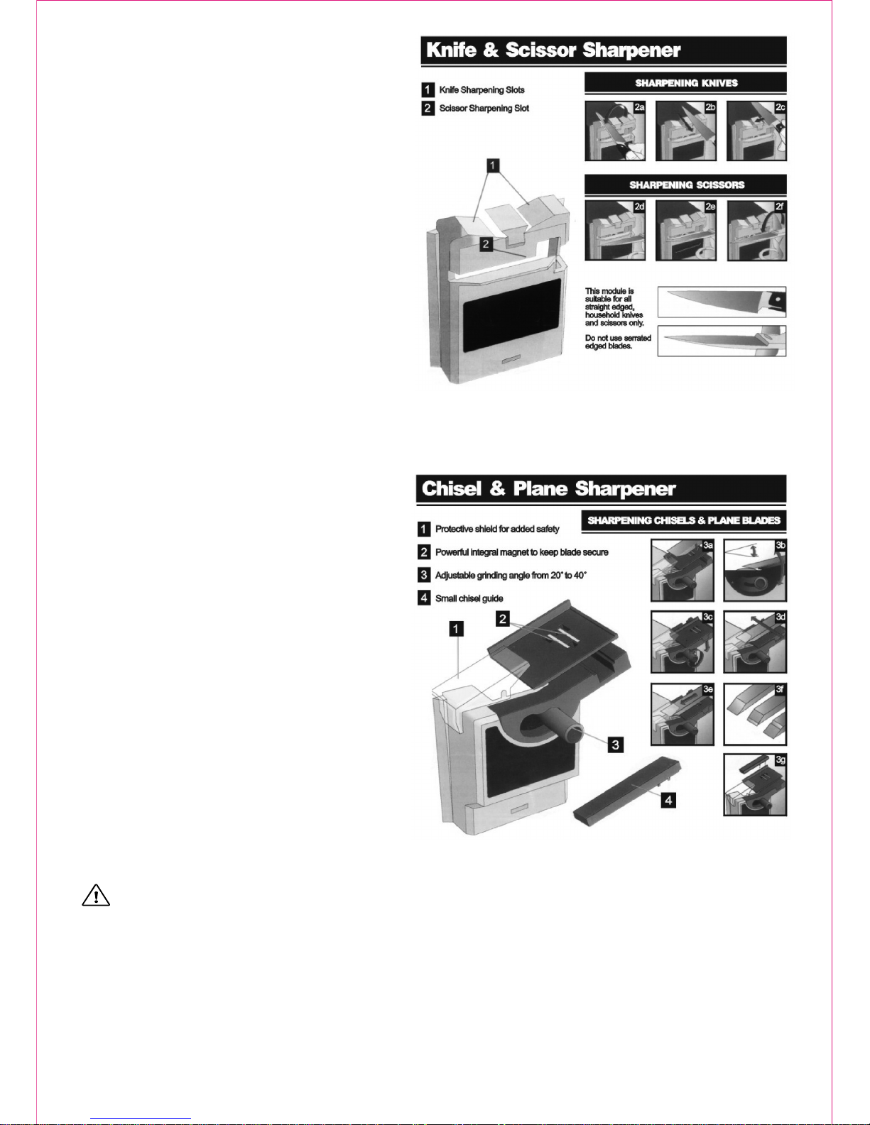
Sharpens all straight-edgedknives and scissors
Unique top forsharpening knives
Precisely angled slotfor sharpening scissors
SHARPENING KNIVES
1.Slide module,labeled Knife &Scissor Sharpener,on to the
Power Unit.
2.Switch PowerUnit on
3.Hold theknife handle towardyou and insertthe handle endof
the blade intoguide slot (2a)
4.As soonas the bladetouches the grindingwheel, draw itwith
light, steady pressureacross the wheelto the tip then remove.
Do not presshard (2b).
5.Insert thesecond side ofthe blade intothe other topguide slot
(2c) and repeat#4.
6.Repeat sharpeningeach side inturn until aclean, sharp edge
is attained.
7.Switch thePower Unit off and unplugthe machine. Before
removing the module,ensure the grindingwheel has stopped.
SHARPENING SCISSORS
1.Slide module,labeled Knife &Scissor Sharpener,on to the
Power Unit.
2.Plug inand switch PowerUnit on
3.Open thescissors fully.
4.Slide thefirst scissor bladethrough the frontguide slot (2d)
keep Thepivot of thescissors and otherblade to theright-hand
side.
5.Draw theblade across thegrinding wheel frompivot to tip.
Use a light,steady pressure donot press toohard (2e).
6.Remove andturn scissors overto sharpen thesecond blade (2f)
keep the pivotto the rightand sharpen frompivot to tip.
7.Repeat ifnecessary until clean,sharp edges areachieved.
8.Switch thePower Unit off and unplugthe machine. Beforeremoving the module,ensure the grindingwheel has stopped.
Regrinds Chisel andPlane blades upto 2" (50mm)wide
oo
Adjustable grinding anglefro 20 to 40
Powerful integral magnetto keep bladesecure
Protective shield foradded safety
SHARPENING CHISELS& PLANES
1.Slide module,labeled Chisel &Plane Sharpener,on to the
Power Unit.
2.Plug inand switch PowerUnit on.
3.The sharpeningangle must matchthe existing beveledangle
on the bladetip. Adjust,if necessary.
4.To alter theangle, turn machineoff, loosenthe angle adjusting
knob (3c), adjustthe plate angle then tighten.
5.Make surethe blade edgetouches the grindingwheel, then
switch the PowerUnit on.
6.Slide theblade and platewith light, steadypressure back and
forth across thegrinding wheel ina continuous motion(3d). Do
not hold theblade stationary thiscauses irregular sharpening.
7.Gradually adjustthe blade downthe plate whilesharpening
(3e). Do notpress hard grindgradually,repeating as needed.
8.Remove theblade and makesure the bevelededge and tip
are evenly sharp.If not, adjustthe grinding angle.It is important
that the sharpeningangle matches theexisting beveled angleof
the blade.This avoids removingtoo much metalunnecessarily
and keeps planeblades at theiroptimum shaving angle(3f).
9.When sharpeningthin chisel blades,place the smallchisel guide
Onto the plateto act asa spacer andsharpen as before(3g).
10.Switch thePower Unit off and unplug.Before removing themodule,
Ensure Thegrinding wheel hasstopped.
11.It is recommendedthat after grinding,the blade tipbe honed on
an oil stone.
MAINTENANCE
WARNING:Make sure thistool is disconnectedfrom its powersource before attemptingany maintenance, cleaning,or inspection.
·Maintain your sharpener. It isrecommended that thegeneral condition ofany tool beexamined before itis used. Keepyour tools ingood
repair by adoptinga program ofconscientious repair andmaintenance in accordancewith the recommendedprocedures found inthis
manual. If anyabnormal vibrations ornoise occurs, turnthe tool off immediately andhave the problemcorrected before furtheruse. Have
necessary repairs madeby qualified servicepersonnel.
·Keep cutting toolssharp and clean.Properly maintained cuttingtools with sharpcutting edges areless likely tobind and areeasier to
control. Keep handlesdry,clean, and freefrom oil andgrease.
·Cleaning. Keep yoursharpener clean andfree from oiland grease. Useonly soap anda damp clothto clean yourtools. Many household
cleaners are harmfulto plastics andother insulation. Neverlet liquid getinside a tool.
3 OF 5

DIAGRAM
4 OF 5

PARTSLIST
For replacement partsand technical questions,please call1-800-222-5381.
PLEASE READTHE FOLLOWINGCAREFULLY
THE MANUFACTURERAND/OR DISTRIBUTORHAS PROVIDED THEPARTSDIAGRAM IN THISMANUAL ASAREFERENCE TOOL
ONLY. NETHER THEMANUFACTURER NORDISTRIBUTOR MAKESANY REPRESENTATIONOR WARRANTYOF ANYKIND TOTHE
BUYER THAT HE ORSHE IS QUALIFIEDTO MAKEANY REPAIRS TOTHE PRODUCT ORTHATHE OR SHEIS QUALIFIED TO
REPLACE ANYPARTSOF THE PRODUCT. IN FACT,THE MANUFACTURERAND/OR DISTRIBUTOREXPRESSLYSTATES THAT ALL
REPAIRSAND PARTS REPLACEMENTS SHOULDBE UNDERTAKEN BYCERTIFIED ANDLICENSED TECHNICIANSAND NOT BY
THE BUYER. THEBUYER ASSUMESALL RISKAND LIABILITYARISING OUTOF HIS ORHER REPAIRS TOTHE ORIGINAL
PRODUCT OR REPLACEMENTPARTSTHERETO ORARISING OUTOF HIS ORHER INSTALLATIONOF REPLACEMENT PARTS
THERETO.
Note: Some partsare listed andshown for illustrationpurposes only andare not
available individually asreplacement parts.
5 OF 5
Part No.
1
2
3
4
5
6
7
8
9
10
11
12
13
14
15
16
17
18
19
20
Description
TopHousing
Base
Switch
Motor
Wheel Valve
Grinding Wheel
Sign for RotationalDirection
Nut
Cord
Jacket of Cable
Screw
PCB
Pilable Foot
Screw
Fixing Chuck forDrill
Supporting chuckfor drill
Locking Lump
Gripping Lump
Locknut
Counter Card
Qty'
1
1
1
1
1
1
1
1
1
1
2
1
4
4
1
1
1
1
1
1
21
22
23
24
25
26
27
28
29
30
31
32
33
34
35
36
37
38
39
40
Description
Right-chuck
Backing iron sheet
Fixing sheet
Screw
Fixing shelf forScissors
Plane Blade Holder
Locknut
Angle conditioner
Supporting Shelf
Move Instruction
Protective Guard
Magnet Card
Magnet
Screw
Fuse Tube
Fuse
Fuse Tube
Auiliary Switch
Botton
Platen
Qty'
1
1
1
1
1
1
1
1
1
1
1
2
1
1
1
1
1
1
1
2
Part No.

WARNING
Some dustcreated bypower sanding,sawing, grinding,drilling, andother constructionactivities contains
chemicals knownto theState ofCalifornia tocause cancer, birthdefects orother reproductiveharm. Some
examples ofthese chemicalsare:
Lead fromlead-based paints
Crystalline silicafrom bricksand cementand othermasonry products,and arsenicand chromiumfrom
chemically-treated lumber.
Yourrisk fromthese exposuresvaries, dependingon howoften youdo thistype ofwork. To reduceyour
exposure tothese chemicals:work ina wellventilated area,and workwith approvedsafety equipment,such
as thosedust masksthat arespecially designedto filterout microscopicparticles.
·
·
Table of contents
Other Northern Power Tools manuals

Popular Power Tools manuals by other brands


Atlas Copco
Atlas Copco LMS68 GOR25 Product instructions

BorMann
BorMann BPT1250 manual

Wilton
Wilton MECHANICS PRO Series manual

Current Tools
Current Tools 252 Assembly, Operating, Safety and Parts Manual

Omer
Omer 4097.16 ROP Installation, user manual and spare parts list

Metabo
Metabo PowerMaxx BS Original instructions


