NorttSa~
HORIZON
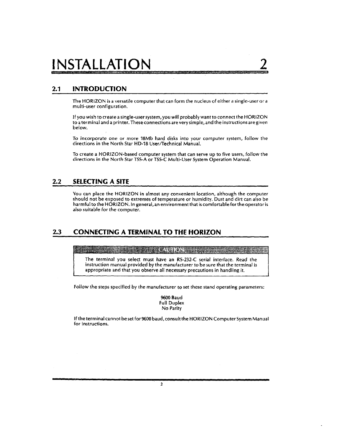
USER
GUIDE
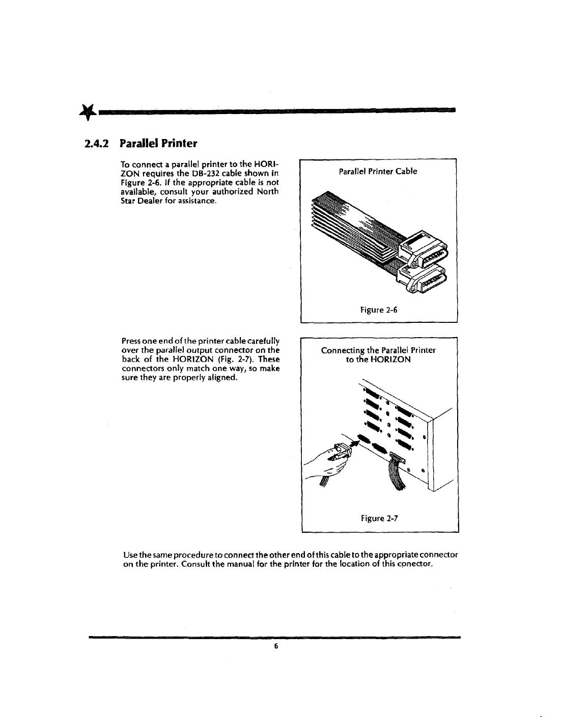
UNPACKING 1
M·P."
£
W¥GM
'+WMWMMM
lift
the
HORIZON and
the
foam packing
material
out
of the shipping container.
Unpacking
the HORIZON
-=::::::::
~
Figure 1-1
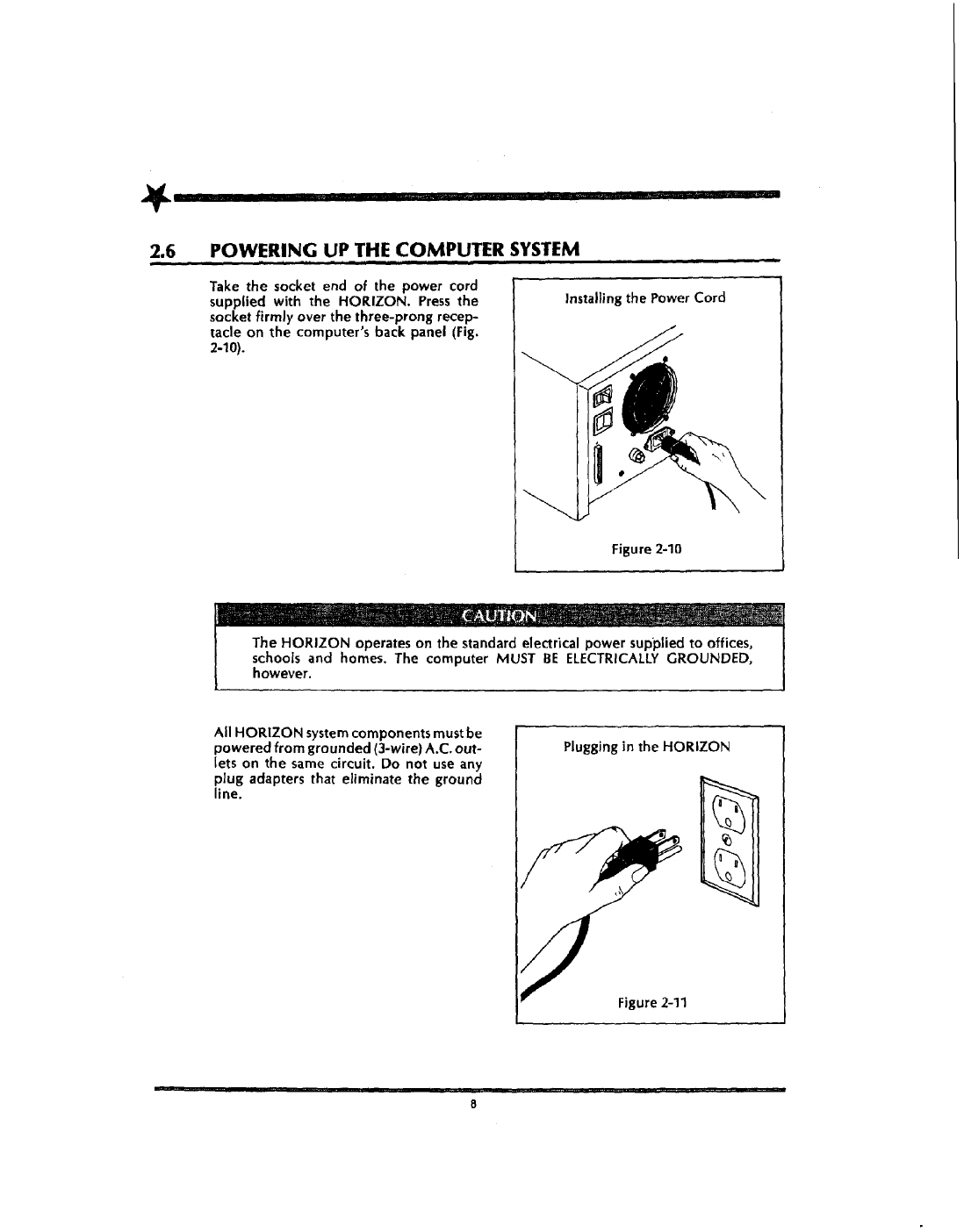
Remove
the
packingmaterial.Place
the
HORIZON
on
aflat surfacecapableofsupporting a
weight of
about
SO
pounds.
In
addition to
the
packing materials and this User Guide,
the
container should
indude:
•HORIZON Computer
•
A.C.
Power Cord
•Documentation and Diskette Package
Verify
that the contents of the container match this list.
Should you find that anything
is
missing from
the
container,
or
should there appear
to
be
damage
due
to shipping, please notify your dealer immediately.
Keep
the
shipping container and packing material.
If
you need
to
return your
HORIZON
to
the
faaory, the computer must arrive undamaged to qualify for
warranty service. Repacking the computer
in
the
original container
prOVides
the
best
proteaion
for
it.
Nonh
Star Computers. Inc 14440 Catalina
5t
.San
La.ndro.
CA
94517 USA
1415)
357-8500 TWXlTelex (910) 366-7001
00450B