Norton Clipper CDR 252 User manual

CDR 252
OPERATING INSTRUCTIONS
Translation of the original instructions

VERS.2015.04.21 CDR 252_MAN_EN
2

VERS.2015.04.21 CDR 252_MAN_EN
3
The undersigned manufacturer:
SAINT - GOBAIN ABRASIVES S.A.
190, BD. J. F. KENNEDY
L-4930 BASCHARAGE
Declares that this product:
« Drill Rigs »: KIT CDR 252 + CDM 203 Code : 70184693970
is in conformity with the following Directives :
"MACHINES" 2006/42/CE
"LOW VOLTAGE" 2006/95/CE
"ELECTROMAGNETIC COMPATIBILITY " 2004/108/CE
"NOISE" 2000/14/CE
And the European standard:
EN 12348 –Core drilling machines on stand –Safety
Valid for machines as of serial number:
70100000
Storage site for the technical documents:
Saint-Gobain Abrasives 190, Bd. J. F. Kennedy 4930 BASCHARAGE, LUXEMBOURG
This declaration of conformity loses its validity when the product is converted or modified without
agreement.
Bascharage, Luxembourg, 01/02/2012.
Olivier Plenert, executive officer.
Declaration of conformity

VERS.2015.04.21 CDR 252_MAN_EN
4

VERS.2015.04.21 CDR 252_MAN_EN
5
CDR 252
OPERATING INSTRUCTIONS
1BASIC SAFETY INSTRUCTIONS 6
1.1 Symbols 6
1.2 Machine plate 7
1.3 Safety instructions for particular operating phases 7
2MACHINE DESCRIPTION 8
2.1 Short description 8
2.2 Purpose of use 8
2.3 Layout 8
2.4 Technical Data 9
2.5 Statement regarding the vibration emission 10
2.6 Statement regarding noise emission 11
3ASSEMBLY AND COMMISSIONING 12
3.1 Assembling the motor on the rig 12
3.2 Tool assembly 12
3.3 Electrical connections 12
3.4 Changing motor speed 13
3.5 Water cooling 13
4TRANSPORT AND STORING 14
4.1 Securing for transport 14
4.2 Transport procedure 14
4.3 Long period of inactivity 14
5OPERATING THE MACHINE 15
5.1 Site of work 15
5.2 Cutting method 15
6MAINTENANCE AND SERVICING 19
7FAULTS: CAUSES AND CURES 20
7.1 Fault-finding procedures 20
7.2 Trouble-shooting guide 20
7.3 Customer service 21
8APPENDIX 23
8.1 Ideal rotation speed of the core bit in relation to the hole diameter 23

VERS.2015.04.21 CDR 252_MAN_EN
6
1 BASIC SAFETY INSTRUCTIONS
The core drill rig CDR 252 is exclusively designed for the drilling of construction products
mainly within a Construction Site.
Uses other than the manufacturer's instructions shall be considered as contravening the
regulations. The manufacturer shall not be held responsible for any resulting damage. Any
risk shall be borne entirely by the user. Observing the operating instructions and compliance
with inspection and servicing requirements shall also be considered as included under use in
accordance with the regulations.
1.1 Symbols
Important warnings and pieces of advice are indicated on the machine using symbols. The
following symbols are used on the machine:
Read operator’s instructions
Ear protection must be worn
Hand protection must be worn
Eye protection shall be worn
Airway protection must be worn

VERS.2015.04.21 CDR 252_MAN_EN
7
1.2 Machine plate
Important data can be found on the following plate located on the machine:
1.3 Safety instructions for particular operating phases
Before commencing work
Before commencing work, make yourself familiar with the working environment at the
place of use. The working environment includes: obstacles in the area of work and
manoeuvre, the firmness of the floor, necessary protection at the site relating to public
thoroughfares and the availability of help in the event of accidents.
Immediately remove damaged or badly worn core bits, as they endanger the operator
whilst rotating.
Only fit NORTON diamond core bits to the machine! The use of other tools can damage
the machine!
Read the core bits’ specifications carefully to choose the adequate tool to your
application.
Make sure the handle of the machine is free from oil or grease.
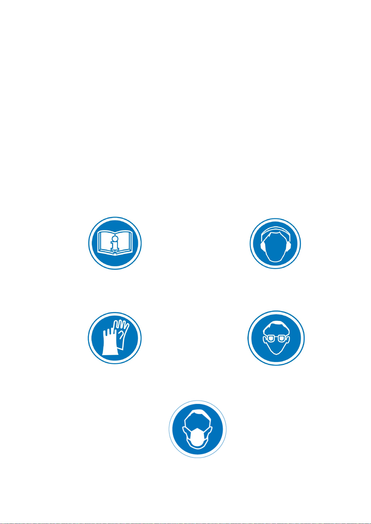
Attention is drawn to the use of BS2092 safety goggles in conformity with specified
Processes No.8 of the Protection of Eyes Regulation 1974, Regulation 2(2) Part 1.
Make sure that no mounting tool is left on the machine before starting it.
Electrical powered machine
Make sure that the electrical supply of the machine is equipped with a grounded
protective connector. If you have doubts, let a qualified electrician check the electrical
system.
Never pull the machine by the cable to transport it or to separate it from the electrical
supply.
Avoid any contact between the cable and extension cable and heat sources, oil, and
sharp edges.
Always check the cable before commencing work. If it is damaged, let a qualified
electrician replace it.
Switch the machine off, and isolate it from the main electrical supply before attempting
any maintenance or repair on the machine
In the event of the machine breaking down or stopping for no apparent reason, switch off
the main electricity supply. Only a qualified electrician is allowed to investigate the
trouble and remedy the fault.
Always isolate the machine from the electrical supply when not in use.
Machine Model
Machine Code
Weight
Year of production
Machine type
Serial number

VERS.2015.04.21 CDR 252_MAN_EN
8
2 MACHINE DESCRIPTION
Any modification, which could lead to a change in the original characteristics of the machine,
may be done only by Saint-Gobain Abrasives who shall confirm that the machine is still in
conformity with the safety regulations.
2.1 Short description
The CDR 252 core drill rig is designed for durability and high performance for onsite wet and
dry drilling operations of a wide range of masonry and natural stone products.
As with all other NORTON products, the operator will immediately appreciate the attention
given to detail and quality of materials used in construction. The machine and its component
parts are assembled to high standards assuring long life and minimum maintenance.
2.2 Purpose of use
The machine is designed for drilling a large range of building materials. It is not designed for
drilling wood or metals, except steel reinforcing securely embedded in concrete.
2.3 Layout
There are two main parts on the core drilling rig CDR 252: the motor and the rig itself.
The rig is made of sectional aluminium, which reduces the weight of the machine allowing
easy transportation. The base ensures stability of the rig, and allows two ways of fixing the
rig: using a vacuum pump or fixing anchors. The rig is equipped with a quick fixing plate, so
the motor can be fitted or removed quickly from the rig.
Three different types of electric motor are available on the CDR 252, offering excellent
quality of drilling and extended life duration. Every motor is equipped with a P.R.C.D.
(Portable Residual Current Device). This circuit breaker protects the motor from an electrical
overload. The P.R.C.D. is a circuit breaker and not a switch. Always stop the motor using its
switch and not the P.R.C.D.

VERS.2015.04.21 CDR 252_MAN_EN
9
2.4 Technical Data
Max. drill bit diameter
252mm
Movement
625mm
Tilting
45°
Weight
11kg (00310387341 CDR 252D Dowel base)
Dimensions
(Length x width x height)
235x325x975mm
You can find the code number on the machine plate. If you bought a complete kit, your
machine is composed of a column with combined base, a motor and a motor mounting plate.
These are the characteristics of the motor:
70184647808
Motor
CDM 203
Power
2 kW
Motor protection
P.R.C.D. 10mA
Rotation speed
450/1050/2000 min-1
Weight
8,2 kg
Range of core bit diameter
15-200mm
Connector
½’’ + 1¼’’

VERS.2015.04.21 CDR 252_MAN_EN
10
2.5 Statement regarding the vibration emission
Declared value of vibration emission following EN 12096.
Machine
Model / code
Measured value of vibration
emission at m/s2
Uncertainty K
m/s2
Tool used
Model / code
KIT CDR 252 +
CDM 203
70184693970
<2.5
0.5
Pro CB BETON
The vibration value is lower and does not exceed 2.5 m/s².
Values determined using the procedure described in the standard EN 12348.
The measurements are made with new machines. Actual values may vary with site
conditions, in terms of:
Materials worked
Wear Machine
Lack of maintenance
Inappropriate tool for application
Tool in poor condition
Unskilled operator
Etc…
The exposure time to vibration is based on the performance of work (related to the
adequacy Machine / Tool / worked material / operator)
When evaluating risks due to hand-arm vibration, you need to take into account effective
usage at rated power of machine during a full day of work; quite often you will realise that
effective utilisation time represents around 50% of overall duration of work. You have to
consider, of course, breaks, water feeding, preparation of work, time to move the
machine, disk mounting…

VERS.2015.04.21 CDR 252_MAN_EN
11
2.6 Statement regarding noise emission
Declared value of noise emission following EN ISO 11201 and NF EN ISO 3744.
Machine
Model / code
Sound
Pressure level
LPeq
EN ISO 11201
Uncertainty K
(Sound
Pressure level
LPeq
EN ISO 11201)
Sound power
level
LWeq
NF EN ISO 3744
Uncertainty K
(Sound power level
LWeq
NF EN ISO 3744)
KIT CDR 252 +
CDM 203
70184693970
94 dB(A)
2.5 dB(A)
105 dB(A)
4 dB(A)
Values determined using the procedure described in the standard EN 12348.
The measurements are made with new machines. Actual values may vary with site
conditions, in terms of:
Wear Machine
Lack of maintenance
Inappropriate tool for application
Tool in poor condition
Unskilled operator
Etc…
Measured values relate to an operator in normal use, as described in the manual
position.

VERS.2015.04.21 CDR 252_MAN_EN
12
3 ASSEMBLY AND COMMISSIONING
3.1 Assembling the motor on the rig
If you bought a complete kit, the motor quick mounting plate and your motor are already
assembled.
To assemble the plate on your motor:
tighten the 4 screws through the plate in the motor.
Then, you can assemble the motor on rig by just slipping this plate in the corresponding
device on the drilling head. Tighten the plate on the rig using the handle.
3.2 Tool assembly
Only NORTON core bit can be used with the CDR 252.
All tools used must be selected with regard to their maximum permitted cutting speed for the
machine’s maximum permitted rotation speed.
Before assembling a new bit into the machine, switch it off and isolate it from the main
source of electricity.
To assemble a new bit, follow these steps:
Remove the motor from the rig.
Use two spanners to dismount the old bit: one to lock the motor axle, and the other to
unscrew the bit. Do not grip on threaded parts.
Grease the thread of the motor axle and of the bit.
For bits with a 1¼‘’ fitting, insert a bronze or brass washer between the motor axle and
the core bit.
Adapters are available in case core bit and motor axle do not fit together.
Screw the new core bit. Tighten using the two spanners. Check that it is completely
locked on the motor axle.
3.3 Electrical connections
Electrical connections
Check that,
the voltage/phase/current supply corresponds to the information indicated on the motor
plate.
available power supply has a ground connection in conformity with safety regulations. If
you have any doubt, let a qualified electrician verify your installation.
the connecting cables should have at least a 2.5mm2-section per phase if you use
extensions.

VERS.2015.04.21 CDR 252_MAN_EN
13
Security Device P.R.C.D.
This circuit breaker must be connected to an electrical supply having the neutral connector
and the earth connector separated. If there is a connection between these two connectors
anywhere on the electrical net, the P.R.C.D. will automatically cut the circuit.
Therefore, check with a qualified electrician, that this separation is correctly made on your
electrical system.
If you use extension cables, make sure they have three wires.
This device can be uncertain with a generator. Ask the manufacturer of the generator if the
coils are properly separated.
This device works also as NVR (“No Volt Release”). It stops the electrical supply of the
machine during a power cut. Therefore, when electricity returns, the machine will not start.
You have to reengage the P.R.C.D. to continue to work.
Before working with the CDR 252, you have to test the P.R.C.D. In order to achieve this
follow these instructions:
Connect the motor to the electrical supply.
Engage the P.R.C.D. on I (or ON).
Press the T (or TEST) button: the P.R.C.D. has to trip on 0 (or OFF).
If the P.R.C.D. trips during work, switch the machine off, and separate it from the electrical
supply. Examine and repair the fault by checking every element of the system (connectors,
cables, motor).
3.4 Changing motor speed
Always switch the motor off before changing speed. Turn the gear change lever on the next
or previous gear. Turn the bit spindle by hand to allow the gear alignment.
Repeat these operations until you reach the required gear.
3.5 Water cooling
Ensure that water is flowing freely in the circuit as insufficient water supply may result in
premature failure of the diamond core bit.
To supply the machine with water:
Use the connector on the side of the motor. You can use either the water supply or a
manual or electrical pump.
Check if the water flow is right by looking through the cutting water. If it is fluid, the flow
rate is correct. If it is not fluid, but like mud or paste, you either have to check if the water
system is blocked, or increase the water flow rate.
Obstruct the existing hole when have to enlarge it, so you can obtain a correct cooling
water inflow.
Eliminate the water escape ways and increase the flow rate to the maximum when you
have to drill porous or cracked materials, or make a second drill.
Use a water-collecting device when you drill overhead.
In case of frost, empty the water cooling system.

VERS.2015.04.21 CDR 252_MAN_EN
14
4 TRANSPORT AND STORING
Take the following measures in order to transport the CDR 252 securely.
4.1 Securing for transport
Dismount the core bit, separate the motor from the rig, and the motor from electrical supply.
4.2 Transport procedure
Use only surface transport to move the CDR 252. Use the handle to carry the rig. No part of
the machine has been designed to lift the CDR 252.
4.3 Long period of inactivity
If the machine is not going to be used for a long period, completely clean the machine. Store
the machine in a dry aired and clean place.

VERS.2015.04.21 CDR 252_MAN_EN
15
5 OPERATING THE MACHINE
You will find useful description of how to use the machine properly.
5.1 Site of work
5.1.1 Siting the machine
Remove from the site anything, which might hinder the working procedure!
Make sure the site is sufficiently well lit!
Observe the conditions for connecting to power supplies!
Place electric cables in such a way that damage by the CDR 252 is excluded!
Make sure you have a continual adequate view of the working area so you can intervene
in the working process at any time!
Keep other staff out of the area, so you can work securely.
5.1.2 Space required for operation and maintenance
Leave 2 m around the machine for usage and maintenance of the CDR 252.
5.2 Cutting method
5.2.1 Preparing the cut
Make sure that it is well anchored or clamped firmly when the material to be drilled is not
part of a big construction.
Before drilling a reinforced-concrete construction, make sure you will not damage the
structure.
Make sure the drilling will not damage any gas or plumbing pipelines, or electrical wires.
Only use the plastic handle of the machine, and no metal parts, to operate the CDR 252,
especially when electrical wires might be submerged.
Make sure before drilling that the core will not cause damage to anything or anyone by
falling out of the hole. Always delimit and sign the working area and place warning
signals around it.
If the core can cause damage by falling out of the hole, make the right framework to hold
the core when you stop drilling.
To choose the core bit rotation speed, use the graph on page, which gives the range of
speed to use according to the diameter of the hole.
Before starting your work, check the fixing and stability of the core bit.
Use the right tools as recommended by the manufacturer depending on the material to
be drilled and the required efficiency.
Apply cooling water continuously whilst drilling and in good time!

VERS.2015.04.21 CDR 252_MAN_EN
16
5.2.2 Fixing the rig
Only use NORTON tools to fix the rig. Always fix the rig before assembling the motor on the
rig. When drilling overhead or horizontally into a wall, extra safety provision should be made
with the use of a support sling to the drilling rig, in case of failure of anchor or vacuum.
Fixation with a dowel
To fix the drill rig, you need a 15mm-dowel, a 30cm-long threaded rod, a washer and a wing
nut.
Bore a 15mm-diameter and 50mm-depth hole and clean it.
Use the appropriate tool to set the dowel in the hole.
Screw the threaded rod in the dowel.
Place the rig so that the threaded rod goes through the oblong hole in the base.
Insert the washer on the rod, and screw the wing nut thoroughly.
You can adjust the rig by using the screws in the corners of the base.
Fixation with a vacuum pump
Fix the pump on the base of the rig.
Place the rubber joint under the base.
Place the machine where you want to bore, and hold it firmly.
Start the vacuum pump. You have to reach a pressure under 0,65bar to have a sufficient
adhesion of the rig.
If you cannot reach this pressure, try to smooth the surface for example with plaster.
5.2.3 Drilling perpendicularly to the surface
Once your motor is engaged on the right gear, and the rig placed and fixed at the right
position, you can begin your cut. Follow these instructions:
Put the handle back on the nut, which allows the movement of the cutting head.
Engage the P.R.C.D.
Open the water supply.
Start the motor with the core bit not touching the surface.
Using the handle, lower slowly the core bit until it lightly touches the surface.
Slowly turn the handle to make the first centimetre of your drilling. By doing so, you
ensure that your hole will be perfectly centred.
You can then increase the drilling feed speed. If you drill too slowly, you lower the
machine efficiency. Drilling too fast results in premature wear of the diamond segments.

VERS.2015.04.21 CDR 252_MAN_EN
17
5.2.4 Slanting holes
You can incline the rig to make slanting holes:
Remove the screw on the front of the rig, and loosen the two screws on the side of the
rig. Keep the front screw, as you will have to reassemble it next you want to use the rig
perpendicularly to the surface.
Loosen the locking handle on the brace bracket.
Adjust the rig until you reached the required angle.
Retighten the two screws on the side of the rig.
Start drilling very slowly because the bit attacks the drilled material only with a little part of its
cutting surface, even with only one of its diamond segments. By drilling slowly, you avoid
misalignment of the core bit.
5.2.5 Drilling of steel rods in reinforced concrete
When you see that:
The core bit goes ahead very slowly.
The force you have to make on the hand wheel increases.
The water going out of the hole is clear and there are some metallic splints in it.
You are going through the steel rods for reinforced concrete. Follow these instructions:
If possible, select a lower gear. Remember that you must firstly take the core bit out of
the hole and switch the motor off in order to change from gear.
Reduce the thrust on the core bit.
Once you have finished cutting the rods, you can reselect the initial gear and drilling speed.
5.2.6 Mechanical clutch
The motor is equipped with a mechanical clutch. It protects against mechanical overload of
the motor. However, the motor might be damaged if it works longer than two seconds.
Therefore reduce the drilling force and switch the motor off.
5.2.7 Breakaway of a segment
When diamond segments, slivers of steel or parts of your drilled material come away during
drilling, and prevent the core bit from drilling, abandon the hole and make another hole, with
the same axis of the first but with an larger diameter (15-20mm).
5.2.8 End of the drilling
When you have made the hole you want to drill:
Lift the core bit out of the hole.
Stop the motor by using the switch and not the P.R.C.D.
Stop the water supply.

VERS.2015.04.21 CDR 252_MAN_EN
18
5.2.9 Pulling the core out of the bit
Unscrew the core bit from the motor axle.
Hold the bit vertically.
Beat lightly the tube of core bit with a wood hammer until the core goes out. Never beat
the core bit with violence against a wall or with tools like hammers or wrenches.
Otherwise, you may distort the tube, preventing the core from coming out of the core bit
and the re-use of the bit.
If the core is stuck into the bit, try to crush it with a chisel. Be careful not to damage the
core bit.
5.2.10 Pulling the core out of the hole (blind holes)
Using a wedge or a lever, snap the core.
To extract the core out of the hole use the special pliers or a wire loop, or make a little
hole into the top of the core and put into it an eyebolt to pull up and remove the core.
5.2.11 Drilling using an extension rod
To make hole deeper than the tool length:
Make the hole for the full depth of the bit.
Take the bit out of the hole and switch the motor off.
Take the core out of the hole without moving the machine.
Unscrew the core bit from the motor axle and put it into the hole.
Screw the extension rod between the core bit and the motor axle. For 1¼’’ back fitting
end, insert a brass or bronze washer.

VERS.2015.04.21 CDR 252_MAN_EN
19
6 MAINTENANCE AND SERVICING
To ensure a long-term quality from the cutting with the CDR 252, please follow the
maintenance plan below:
Begin of the day
During the changing of the
tool
End of the day
Every week
After a fault
After a damage
Whole machine
Visual control (general aspect,
watertightness)
Clean
Motor cooling fans
Blow the dirt and dust
Switch, cables and extension cables
Inspect
Water hoses and nozzles
Clean
Motor housing
Clean
Reachable nuts and screws
Tighten up
Service the machine only while it is switched off and isolated from the electrical supply.
Cleaning the CDR 252
After work, blow dirt and dust out of all air vents with dry air. Wear protective goggles and
mask for this operation.
Switch, cables and extension cables
Check visually that switch, cables and extension cables are not damaged. If so, get them
replaced by a qualified electrician.
Inspection and control
Return your core drilling motor for service to your nearest Service Center at least every 200
hours of work. At this occasion, ask for the renewal of your carbon brushes.

VERS.2015.04.21 CDR 252_MAN_EN
20
7 FAULTS: CAUSES AND CURES
7.1 Fault-finding procedures
Should any fault occur during the use of the machine, turn it off, and isolate it from the
electric supply. Works dealing with the electric system or supply of the machine can only be
done by a qualified electrician.
7.2 Trouble-shooting guide
Trouble
Possible source
Resolution
Motor is not running
No electricity
Check the electrical
supply (fuse for example)
Defective switch
CAUTION : can only be
solved by qualified
electrician
Defective motor
Change motor or contact
motor manufacturer
Fault due to P.R.C.D.
Check the earth link on
your electrical supply.
Change the P.R.C.D.
Connection cable section
too small
Change connection cable
Defective connection cable
Change connection cable
Motor stops during the cutting,
but can be restarted after a
short period
Drilling advance too quick
Cut slowly
Core bit is blunt
Sharpen the core bit in
calcareous stone
Defective core bit
Change core bit
Core bit is not
corresponding to the
application
Change core bit
No water on the core bit
Water supply closed
Open the water supply
Water supply system is
blocked up
Clean water supply
system
Table of contents
Other Norton Drill manuals
Popular Drill manuals by other brands

Apprentice
Apprentice ACD18K2 Operator's manual

DWT
DWT BM-1050 M Original instructions

Chicago Pneumatic
Chicago Pneumatic CP7300 Series Operator's manual

Dexter Laundry
Dexter Laundry 650ID2.5 instruction manual

EINHELL
EINHELL TE-CD 18/2 Li-i Kit Original operating instructions

Milwaukee
Milwaukee M18 CBLPD-422 Original instructions