NOVACAT 225 ED User manual

/PERATOR@SMANUAL
GB
Ihre / Your / Votre • Masch.Nr. • Fgst.Ident.Nr.
).3425#4)/.3&/202/$5#4$%,)6%290AGE
4RANSLATIONOFTHEORIGINAL/PERATING-ANUAL
Ihre / Your / Votre • Masch.Nr. • Fgst.Ident.Nr.
.R
• Disc mower
99 377.GB.80I.0
NOVACAT 225 ED
(Type PSM 377 : + . . 01001)
NOVACAT 265 ED
(Type PSM 378 : + . . 01001)

ALLG./BA SEITE 2 / 0000-GB
Important information concerning Product
Liability.
According to the laws governing product liability, the manufacturer and dealer are obliged to hand the
operating manual to the customer at the time of sale, and to instruct them in the recommended operating,
safety, and maintenance regulations. Conrmation is necessary to prove that the machine and operating
manual have been handed over accordingly.
For this purpose,
- document A is to be signed and sent to Pöttinger,
- document B remains with the dealer supplying the machine,
- and the customer receives document C.
In accordance with the laws of product liability, every farmer is an entrepreneur.
According to the laws of product liability, property damage is damage caused by a machine and not to
it. An excess of Euro 500 is provided for such a liabilioty.
In accordance with the laws of product liability, entrepreneurial property damages are excluded from
the liability.
Attention! Should the customer resell the machine at a later date, the operating manual must be given
to the new owner who must then be instructed in the recommended regulations referred to herein.
GB Dear Farmer
You have just made an excellent choice. Naturally we are very happy
and wish to congratulate you for having chosen Pöttinger. As your
agricultural partner, we offer you quality and efciency combined with
reliable servicing.
In order to assess the spare-parts demand for our agricultural machines
and to take these demands into consideration when developing new
machines, we would ask you to provide us with some details.
Furthermore, we will also be able to inform you of new developments.

Dokument D
GB-0600 Dokum D Anbaugeräte - 3 -
ALOIS PÖTTINGER Maschinenfabrik GmbH
A-4710 Grieskirchen
Tel. (07248) 600 -0
Telefax (07248) 600-511
GEBR. PÖTTINGER GMBH
D-86899 Landsberg/Lech, Spöttinger-Straße 24
Telefon (0 81 91) 92 99-111 / 112
Telefax (0 81 91) 92 99-188
GEBR. PÖTTINGER GMBH
Servicezentrum
D-86899 Landsberg/Lech, Spöttinger-Straße 24
Telefon (0 81 91) 92 99-130 / 231
Telefax (0 81 91) 59 656
Machine checked according to delivery note. All attached parts removed. All safety equipment, drive shaft and operating
devices at hand.
Operation and maintenance of machine and/or implement according to operating instructions explained to the customer.
Tyres checked re. correct pressure.
Wheel nuts checked re. tightness.
Drive shaft cut to correct lenght.
Correct power-take-off speed indicated.
Fitting to tractor carried out: to three-point linkage
Trial run carried out and no defects found.
Functions explained during trial run.
Pivoting in transporting and operating position explained.
Information given re. optional extras.
Absolute need to read the operating manual indicated.
Please check. X
According to the product liability please check the above mentioned items.
INSTRUCTIONS FOR
PRODUCT DELIVERY
GB
In order to prove that the machine and the operating manual have been properly delivered, a confirmation is necessary.
For this purpose please do the following:
- sign the document A and send it to the company Pöttinger
(in case of Landsberg equipment: to the company Landsberg)
- document B stays with the specialist factory delivering the machine.
- document C stays with the customer.

GB
0800_GB-INHALT_377 - 4 -
WARNING SIGNS
CE sign .............................................................................................. 5
Meaning of warning signs ................................................................. 5
ATTACHING TO TRACTOR
Attaching implement to tractor.......................................................... 6
Adjusting lower links.......................................................................... 7
Important recommendation!.............................................................. 7
Fitting drive shaft .............................................................................. 7
Parking in the open ........................................................................... 7
TRANSPORT- AND WORKING POSITION
Conversion from working to transport position................................. 8
Conversion from transport to working position................................. 8
Transport position - 1 ....................................................................... 9
Transport position - 2 ....................................................................... 9
Transport position - 3 ..................................................................... 10
Transport position - 4 ..................................................................... 10
Reducing the Total Height .............................................................. 10
DISMOUNT AND PARKING
Dismount implement from tractor ................................................... 11
Parking the implement .................................................................... 12
Support Stand ................................................................................. 12
Take care when turning on slopes!.................................................. 13
STARTING WORK
Important points before starting work............................................. 14
Safety hints...................................................................................... 14
Operation......................................................................................... 15
Adjustment ...................................................................................... 15
CONDITIONER
Mowing with the conditioner........................................................... 16
Correct belt tension......................................................................... 16
Position of the rotor prongs............................................................. 16
Dismounting and mounting the conditioner.................................... 17
Mowing without Conditioner ........................................................... 19
Optional extra.................................................................................. 19
Settings ........................................................................................... 21
Cleaning and maintenance.............................................................. 21
SET THE POSITIONS OF THE GUIDING PLATES
"Extra dry" system........................................................................... 22
Dismount guide plate ...................................................................... 23
Mount guide plate ........................................................................... 23
SWATH DISCS
Swath Discs..................................................................................... 24
Flat cone conveyor (Optional extra) ................................................ 24
COLLISION SAFETY DEVICE
Collision safety device..................................................................... 25
How the hydraulic collision safety device functions ....................... 25
Function of collision safety device .................................................. 25
MAINTENANCE
Safety point ..................................................................................... 26
General maintenance hints.............................................................. 26
Cleaning of machine parts .............................................................. 26
Parking in the ope ........................................................................... 26
Winter storage ................................................................................. 26
Drive shafts...................................................................................... 26
Hydraulic unit .................................................................................. 26
Cutter bar oil level check ............................................................... 27
Changing oil - Angular gear............................................................. 28
Installing cutter blades ................................................................... 28
Changing oil - Cutter bar................................................................. 28
Check initial spring tension. ............................................................ 29
Alter spring tension ......................................................................... 29
Tabel: ............................................................................................... 30
Checking wear on mowing blade holders....................................... 31
Holder for a quick change of cutter blades..................................... 32
Checking the mowing blade suspension ........................................ 32
Changing the Cutter Blades (up to 2003 model)............................. 32
Changing the Cutter Blades (from 2004 model).............................. 33
Storing the lever .............................................................................. 33
TECHNICAL DATA
Technical data ................................................................................. 34
Optional equipment:........................................................................ 34
Necessary connections ................................................................... 34
The dened use of the mower unit.................................................. 35
Position of Vehicle Identication Plate ............................................ 35
SUPPLEMENT
Driveshaft ........................................................................................ 39
Lubrication chart ............................................................................. 41
Lubricants........................................................................................ 43
Attachment variations...................................................................... 45
Repairs on the cutter bar................................................................. 46
Combination of tractor and mounted implement............................ 47
- 5 -
9700_GB-Warnbilder_361
GB
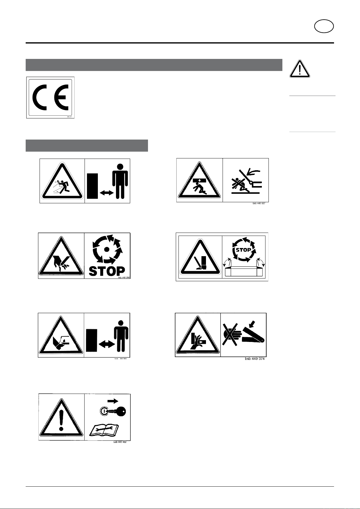
Warning signs
Stay clear of swinging area of implements
Close both side protective coverings before engaging
p.t.o..
Never reach into the crushing danger area as long as
parts may move.
CE sign
The CE sign, which is affixed by the manufacturer, indicates outwardly that this machine
conforms to the engineering guideline regulations and the other relevant EU guidelines.
EU Declaration of Conformity (see supplement)
By signing the EU Declaration of Conformity, the manufacturer declares that the machine being
brought into service complies with all relevant safety and health requirements.
Meaning of warning signs
Danger - flying objects; keep safe distance from the
machine as long as the engine is running.
Wait until all machine components have stopped
completely before touching them.
Stay clear of mower knife area as long as tractor engine
is running with PTO connected.
Shut off engine and remove key before performing
maintenance or repair work.
Recommendations
for work safety
All points referring
to satety in this
manual are
indicated by this
sign.
bsb 447 410
495.167

(348) ANBAU 0000-GB
GB
- 6 -
attaching tO tractOr
Attaching implement to tractor
Safety hints:
see supplement-A1 points 7.), 8a. - 8h.)
- Attach mower so that the edge of the tractor-side drum is just outside the right-hand
tractor tyre!
- See also chapter "Side-located attachment", supplement-D
- Adjust lower link bolt (1) on frame accordingly.
- Bring frame into horizontal position by adjusting linkage arm spindle (15).
- By turning upper link spindle (16) the cutting height is adjusted .
(348) ANBAU 0000-GB
attaching tO tractOr GB
- 7 -
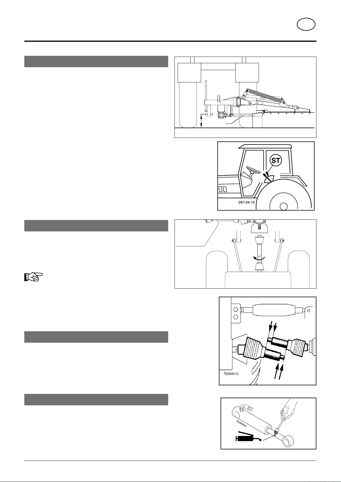
Adjusting lower links
• The drive shaft (GW) position should be approximately horizontal
when mowing.
- Set the tractor's lifting gear accordingly (H1)
- Set the tractor hydraulics (ST) using the bit stop.
This height allows optimal evenness when working on uneven ground
and need not be changed for swinging cutter bar up.
- Connect hydraulic snap coupling for swivel cylinder.
Important recommendation!
A transfer, which is located near the gear, advises which p.t.o. speed
your mower unit is equipped for.
Standard: Gear for power take-off 1000 rpm.
Optional exra: Gear for power take-off 500 rpm.
Order number: spare part book
Fitting drive shaft
- Before operating for the first time, drive shaft is to be checked and
adapted if necessary. See alse chapter "Drive Shaft" in supplement
B.
Parking in the open
When parking for longer periods in the open, clean plunger rods and
then coat with grease.
H1 GW
TD 4-00-1
1000 rpm
540 rpm
TD 18/96/2
Standard (540 rpm)
Standard (540 rpm)
FETT
(348) TRANSPORTSTELLUNG 0400-GB
GB
- 8 -
Attention!
Take care with transport positions 1, 2, 3.
Before swivelling the cutter bar up, turn
off the drive and wait for the mower discs
to come to a complete standstill.
NOTE:
The implement has been so designed that the mower
unit is positioned as close as possible to the tractor.
This has important advantages for both mowing and
transporting operations.
• The implements´s centre of gravity lies close to the
tractor and through this
- less supporting structure load
- less load alleviation of the steering axle when
transporting
- better cutter bar ground adaption when mowing
• Themowerbarcanbeswivelledinto3differentpositions
for transportation.
Safety Precaution!
see supplement-
A1 points 7.), 8c.
- 8h.)
Changing from
working position
to transport
position is only
to be carried out
on even, firm
ground.
Never let mowing
mechanism run
with the mower
raised.
Swinging cutter bar down
- Make sure that
swivelareaisfree
and that nobody
is standing in the
danger area.
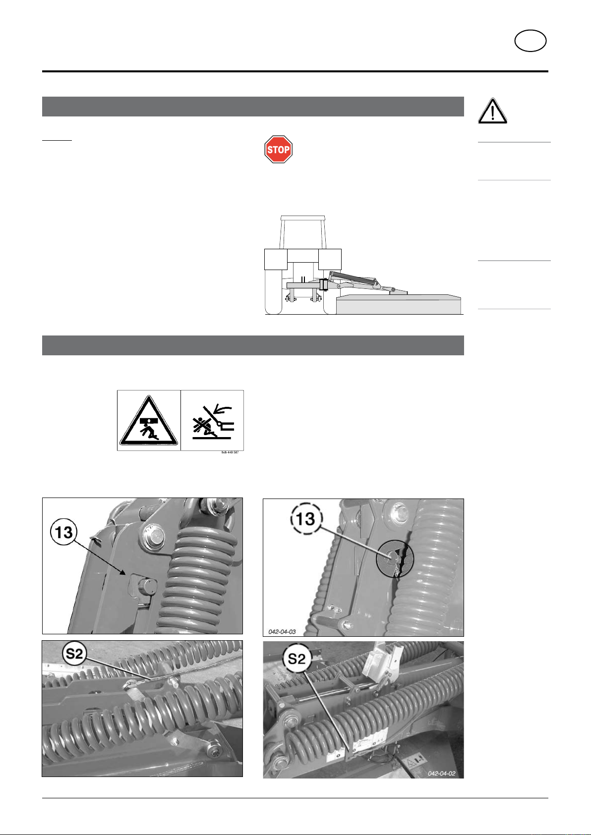
Conversion from working to transport position
Conversion from transport to working position
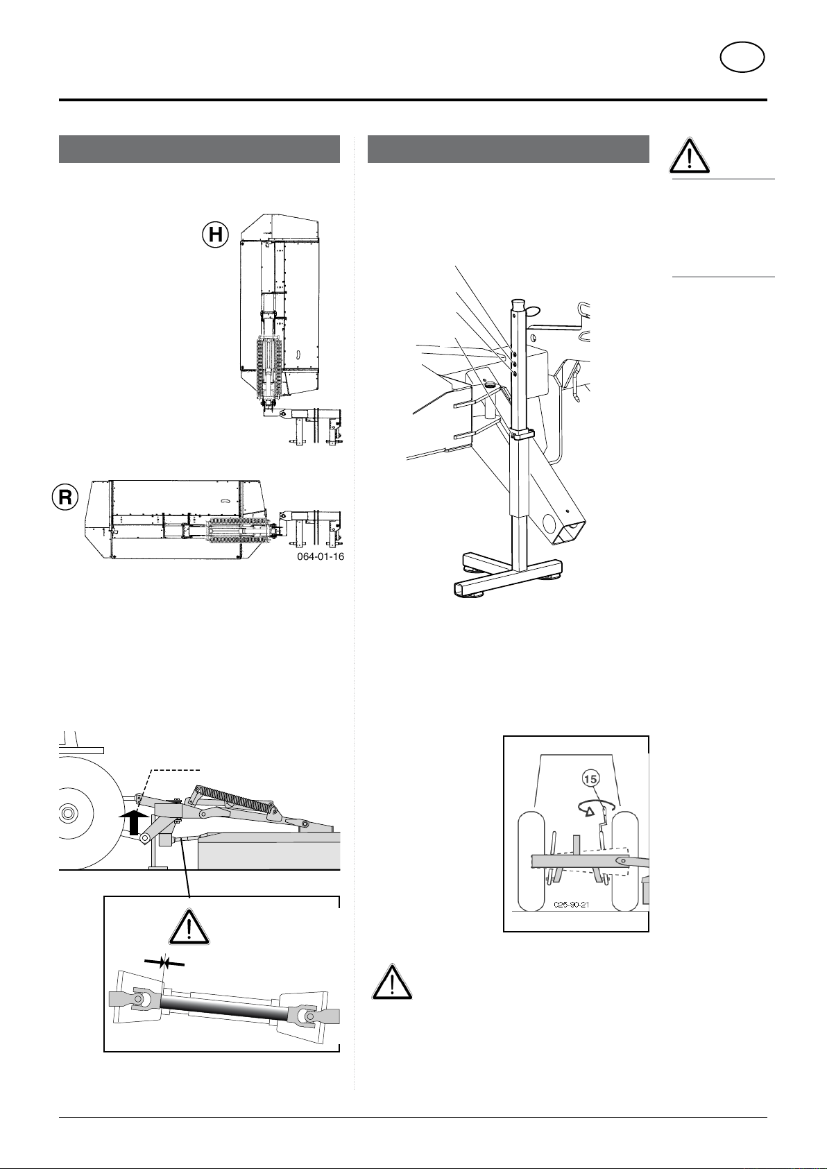
- Gently raise cutter bar with swivel cylinder so that hook
(13) can be released.
- Release hook (13) by pulling on the rope (S2).
- Lower cutter bar hydraulically.
Up to 2003 model From 2004 model
48/00/20
transpOrt- and WOrking pOsitiOn

(348) TRANSPORTSTELLUNG 0400-GB
GB
- 9 -
transpOrt- and WOrking pOsitiOn
Transport position - 2
Mower bar swivelled back.
Cutter bar o the rear and swivelled up until it stops
(approx. 20°)
Note: Only short trips at low speed may be carried
out in this position
Variant 1:
Without hydraulic slewing mechanism
- Lower cutter bar to ground.
- Release bolt (40) by pulling
on the rope (S1) and move
forwards with the tractor.
In doing so, the cutter bar
swivels back so far until
the bolt (40) is locked into
position.
- Raise the implement using
the tractor's lifting gear.
Variant 2:
With hydraulic slewing mechanism
An additional double-action hydraulic connection is
necessary on the tractor.
Ahydraulicunitis installed instead of a mechanicalslewing
unit (with bolts 40). See chapter “Collision Safety”.
- Raise cutter baractuate
single-action control valve (ST)
- Swivel cutter bar to the rearactuate
double-action control valve (ST)
Transport position - 1
Mower bar only swivelled up at the side.
- Pull on rope (S2) and simultaneously actuate servo-
valve (ST).
- Gradually move cutter bar into vertical position and
release rope (S2).
- Secure cutter bar with hook (13).
- Servo-valve (ST) to O
position
Tips for transportation:
Do not move the servo-valve (ST) to the ”float” position.
The hook (13) will become very worn.
- Before driving on roads always check correct
locking!
- Connect lighting and raise implement for transport.
- Before leaving the tractor lower cutter bar to ground!
Ensure a sufficient gap (X1) !
Incombination with larger tractor types, it couldhappen
that there is insufficient gap
to the mud guard or tyre
(X1) which could then cause
a cxollision with the cutter
bar.
If this is the case, this
transport position must not
be used.
It is possible to try to move
the cutter bar further to the
right.
- Insert lower linkage bolts
accordingly (see instructions in the supplement to
this manual)
- However the total sidth must not exeed a
maximum
Attention!
Important
instructions
in the chapter
entitled ”Parking
the implement”
02/00/05
02/00/04
X1
02/00/08
max. 3 m

(348) TRANSPORTSTELLUNG 0400-GB
GB
- 10 -
transpOrt- and WOrking pOsitiOn
Transport position - 3
Cutter bar to the rear and swivelled up (approx.
90°).
1. Swivel mower bar back as described in "Transport
Position - 2".
2. Move mower bar into vertical position as described in
"Transport Position - 1".
- Secure cutter bar with hook (13).
3. Before driving on roads always check correct
locking!
- Connect lighting and raise implement for transport.
- Before leaving the tractor lower cutter bar to ground!
Transport position - 4
Cutter bar laterally swivelled up (approx. 20°)
- this position upwards is limited by a stop buffer.
• only for turning manoeuvres in the field.
• do not use on roads or public thoroughfares!
Reducing the Total Height
Before converting to transport position
• The external guard plate (10) can be swivelled in to
reduce the total height (- 30 cm) when in the transport
position.
Note:
For safety reasons
the mower
disks must be
at a complete
standstill before
swivelling the
guard plate.
02/00/06
TD48/00/21
30cm
10
02/00/07
0400_GB-Abbauen_348
GB
- 11 -
Dismount implement from tractor
Attention!
• Always
park implement
steadfast
• Use
support stand -
otherwise danger
of tipping
• Danger of injury
from crushing
and shearing
sections in
the area of the
support stand
• Follow the
instructions on
the following
page also.
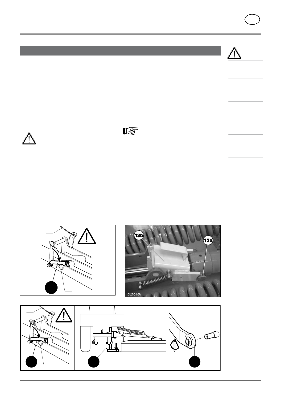
Instructions
The lever 13b is a safety device. It should not be
changed in its form and functions.
Theleverissoconstructed thatitwillnotspringoutfrom
the bolt position (13b, 13a) during hydraulically slewing
of the mowing bar. The lever is thus only damaged
(deformed) but remains in the bolt position.
Thishas been arranged by the manufacturer – forsafety
reasons.
• Do not operate the hydraulic cylinder to
slewacrossthemowing bar whenthe lever
is in the bolt position
• Exchangedamagedleversimmediatelyfor
new ones.
Important!
Keep to the order of operation
1. Shift servo to floating position so that no residual air
pressure remains in hydraulic lines.
2. Let bolt (13a) rest in the hook.
- Pull the rope (S2)
- Lower mounting frame with lifting gear until the bolt
(13a) rests in the hook.
3. Move the lever (13b) to the locking position
Doing this secures the bolt (13a) in the hook
This safeguard is important!
Otherwise the danger exists that the
mounting frame of the cutter bar could
swivelupinjerksandjoltswhenuncoupling
the lower link
4. Bring support stand (14) into support position and
secure with linch pin
5. Lower lifting gear far enough so that implement stands
on support stand on the ground
6. Dismount implement from tractor (15)
- Uncouple drive shaft.
- Uncouple hydraulic lines.
- Remove rope from tractor cabin.
Up to 2003 model From 2004 model
15
14
495-733a
S2
13a
13b
15
14
495-733a
S2
13a
13b
dismOunt and parking
0400_GB-Abbauen_348
GB
- 12 -
dismOunt and parking
Support Stand
The support stand can be pinned in 4 positions
Positions 1, 2, 3: when parking the implement
Position 4: For transport and operating positions
Parking the implement on the support stand
Any position (1, 2, 3) can be chosen which enables
lifting gear to be uncoupled without problems.
Nevertheless, should a problem arise when
uncoupling the lifting gear
- park the implement on
flat, firm ground
- turn the lower link
adjusting spindle (15)
far enough so that
the lower link can be
pulled from the bolt.
Caution!
Crushing and shearing sections in the lifting
gear area.
Parking the implement
The implement can be parked in two positions (R and
H).
• Donotsetthehydraulic
controlvalveto floating
position if the support
stand is raised.
Attention! (STOP)
The support stand should not be raised too high
- if the implement is parked in ”H” position and the
hydraulic control valve is set to floating position.
The drive shaft could thus be damaged as it is telescoped
on to the bar (0mm).
Beware!
Before
uncoupling
the lower link,
always secure
the bolt 13a with
the lever 13b.
1
2
3
4
48-00-24
064-01-014
STOP
0 mm
064-01-015
(358) 9500-GB HANGFAHRT - 13 -
WOrking On sLOpEs GB
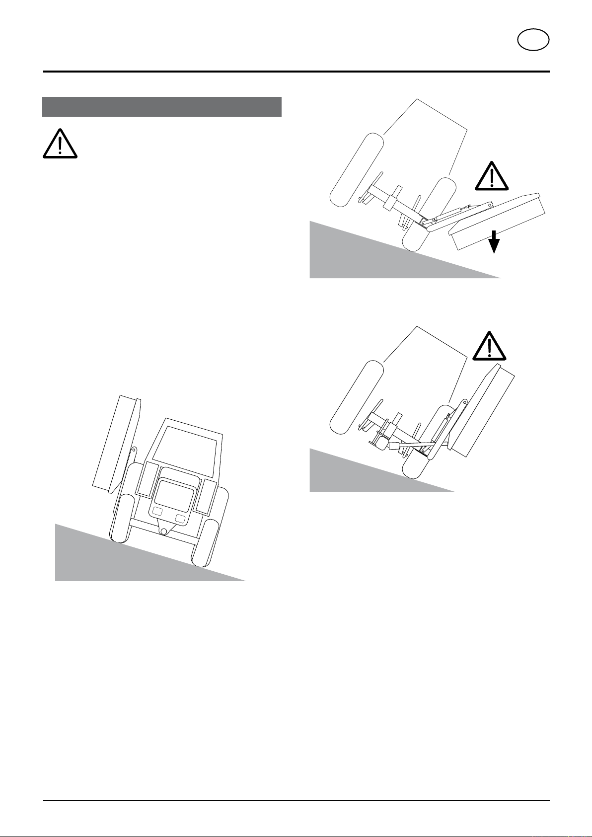
Take care when turning on slopes!
Thetractor'stravelling characteristicsare influenced
by the weight (G) of the mower unit. This can lead to
dangerous situations, especially on slopes.
Danger of tipping occurs
- when the mower unit is facing downhill and in a raised position,
- when travelling in a left-hand curve with the mower unit raised,
- whentravelling in a left-handcurve in the transportposition(mower
unit completely raised).
Safety advice
• Reduce speed in left-hand curves accordingly.
• Travel so that the raised mower unit is facing uphill.
• It is better to travel in reverse on a slope than to carry out a risky
turning manoeuvre.
TD15/95/3
G
TD15/95/2
TD15/95/4

(379) 0100-GB INBETRIEBN - 14 -
GB
starting WOrk
Important points before starting work
Safety hints:
see supplement-A1 points 1. - 7.)
After the first hours of operation
• Retighten all knife screw fittings.
Safety hints
1. Check
- Check the condition of knives and the knife holder.
- Check cutting drums for damage (see also chapter
"Maintenance").
2. Switch-on the machine only in working position and do
not exceed the prescribed power take-off speed (for
example max. 540 rpm).
A transfer, which is located near the gear, advises which p.t.o.
speed your mower unit is equipped for.
• Turn thep.t.o.ononlywhen allsafetydevices(coverings,protective
aprons, casings, etc.) are in proper condition and attached to the
implement in the correct protective positions.
3. Pay attention to correct p.t.o. direction of
rotation!
4. Damage protection!
• Thesurfacetobemowedmustbefreeofobstructions
or foreign objects. Such objects (e.g. large stones,
pieces of wood, boundary stones, etc.) can damage
the mower unit.
In the event of a collision
• Stop immediately and switch off the drive.
• Carefully check the implement for damage. The mowing discs
and their drive shaft must be checked in particulare.
• Have the implement checked also by a specialist workshop if
necessary.
After any contact with foreign objects
• Check the condition of knives and the knife holder (see chapter
"Maintenance and service").
• Retighten all knife screw fittings.
4. Stay clear while engine is running.
- Keep people out of the danger zone - foreign bodies which can
be ejected by the mower could injure them.
Special care is
necessary on
or near stony
ground.
5. Wear hearing protection
The noise level in the workplace can deviate from the
measured value (see Technical Data) partly because
of the differing cabin types of various tractors.
• If a noise level of 85 dB (A) is reached or exceeded, the farmer must
have suitable hearing protection in readiness (UVV 1.1 §2).
• If a noise level of 90 dB (A) is reached or exceeded, the hearing
protection must be worn (UVV 1.1 § 16).
01-00-10
4a
540 Upm 100 0 U pm
bsb 447 410
TD8/95/6

(379) 0100-GB INBETRIEBN - 15 -
GB
starting WOrk
Operation
1. Adjust cutting height by turning upper link spindle
(inclination of the cutting discs max. 5°).
2. To mow, gradually supply power to the p.t.o. before
entering the crop and bring the mowing discs up to full
revs.
Smoothly increase the p.t.o. speed, in order to avoid noises in
the free-wheel conditioned by the system.
- Adjust travel speed to terrain and crop.
Adjustment
- Adjust tractor hydraulics in a way that the machine can adapt to
uneven ground.
- Put hydraulic control device (ST) into "free gear" (floating
position or "lower")
- Thedriveshaft(GW)positionshouldbeapproximatelyhorizontal
when mowing.
- Frame horizontal.
- Fix hydraulic lower links in a way that the machine cannot swing
out sideways.
H1 GW
TD 4-00-1
- 16 -
0500-GB AUFBEREITER_348
GB
cOnditiOnEr
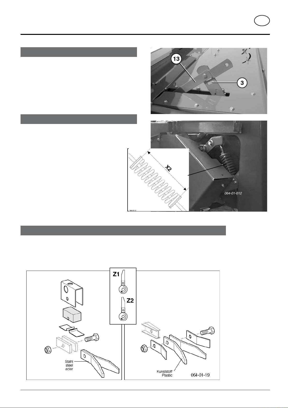
Mowing with the conditioner
The conditioning effect can be modified:
- with lever (13), which adjusts the gap between adjustable plate
and rotor. The conditioning effect is most intense with the lever
at the bottom of its travel (Pos. 3).
However the crop should not be chopped.
Correct belt tension
Check X2 size
NOVACAT 225: X2 = 164 mm
NOVACAT 265: X2 = 164 mm
NOVACAT 305: X2 = 164 mm
EUROCAT 275: X2 = 178 mm
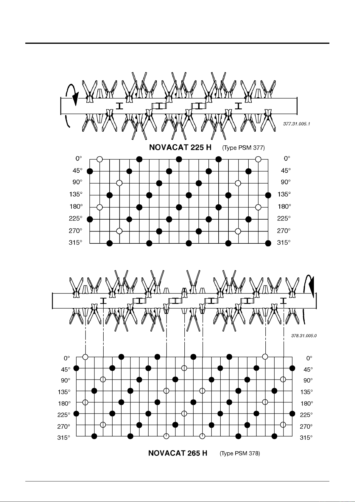
Position of the rotor prongs
Pos. Z1: position of the rotor prongs for normal operating conditions
Pos. Z2: for difficult operating conditions if for example the chuck wraps around the rotor
The rotor prongs turn 180° (pos.Z2). This prong position removes the problem in most cases. The preparation effect is
thereby somewhat reduced.

- 17 -
0500-GB AUFBEREITER_348
GB
cOnditiOnEr
3. Remove belts
- Release the tension using lever (3) beforehand
4. Fit transport wheels (4)
- left and right
- secure with linch pin
Dismounting and mounting the
conditioner
Reduce spring tension before dismounting
the conditioner
Pin bolt (18) in the relative position (a, b, c)
- see chapter "MAINTENANCE"
Otherwise the danger exists that the
mountingframeofthecutterbarcouldswivel
up in jerks and jolts when uncoupling the
1. Loosen locking mechanism (1) and swing
protection (2) up.
2. Remove the belt protection (2) and withdraw
the drive shaft (GW) from the gear.

- 18 -
0500-GB AUFBEREITER_348
GB
cOnditiOnEr
5. Release left and right locks
• Spring loaded positioning bolt up to 2004
model
Remove linch pin (V1) and release bolts
• Pos. A = released
• Pos. B = Locked
• Screwed in from 2004 model
Remove screw (S)
(Spring loaded positioning bolt = optional)
6. Always park conditioner steadfast.
7. Mount the guard (5)
This guard (5) prevents the penetration of dirt into the
gear area.
Mounting the conditioner
- is effected in the reverse sequence to
dismounting.
Important!
When mowing
without
conditioner,
protective
elements and
the both swath
formers (SB)
must be mounted
additionally on the
cutter bar. Parts
see spare parts

- 19 -
0400-GB MÄHEN OHNE CR_375
GB
cOnditiOnEr
Take particular notice when the conditioner is
detached rom the cutter bar
Safety hint
A machine with a conditioner (CR) as a complete unit is fitted with proper
protection elements.
Should the conditioner be detached however, the mowing
unit no longer has complete protection covering. In this
situation mowing may not take place without additional
protection elements!
Beware!
Protection elements, especially intended for this mode of
mowing, must be fitted to the mowing unit.
These protection elements are not included in the delivery
of a new machine with a conditioner, the parts must be
additionallyordered(seeSpareParts List, component group
”REAR PROTECTION”).
Optional extra
- Chassis (4)
- Spring-loaded fixing bolts (A-B)
For mowing without conditioner (CR)
- Observe safety hint (above) without
reservation!
Mowing without Conditioner
- 20 -
0400-D ROTOR_377
This manual suits for next models
1
Table of contents
Popular Lawn Mower manuals by other brands

Snapper
Snapper 6413 parts manual

Husqvarna
Husqvarna P 520D With cabin Operator's manual

Yazoo
Yazoo YHRLD21 Illustrated parts list
 Operator's manual")
Cub Cadet
Cub Cadet RZT 50 (w/50" Mower Deck) Operator's manual

Husqvarna
Husqvarna LB448S Operator's manual

Mr. GARDENER
Mr. GARDENER TRIKE 51 BT I Translation of the original instructions


