NUVE FN 300 User manual

NÜVE SANAYİ MALZEMELERİ İMALAT VE TİCARET A.Ş.
FN 300 - FN 400 - FN 500
FN 400 P –FN 500 P
DRY HEAT STERILIZERS/OVENS
USER’S MANUAL
1984
Z14.K 25 236 Rev. No: 07Rev. Date: 06/2017

1
MANUFACTURER :
NÜVE SANAYİ MALZEMELERİ
İMALAT VE TİCARET A.Ş.
Saracalar Mahallesi, Saracalar Kümeevleri No:4/2 Akyurt 06750
ANKARA - TURKEY
TEL: +(90) 312 399 28 30 (pbx)
FAX: +(90) 312 399 21 97
E-mail: [email protected].tr
WARRANTY CERTIFICATE
1. Nüve warrants that the equipment delivered is free from defects during material and
workmanship. This warranty is provided for a period of two years. The warranty period begins
from the delivery date.
2. Warranty does not apply to parts normally consumed during operation or general maintenance
or any adjustments described in the operating instructions provided with the equipment.
3. Nüve does not accept any liability in the case where the goods are not used in accordance with
their proper intent.
4. The warranty may not be claimed for damages occurred during the shipment, for damages
resulting from improper handling or use, the defects in maintenance, negligence, bad
functioning of auxiliary equipment, in the case of force majeure or accident and incorrect power
supply.
5. In the event of failure, Nüve shall be under no liability for any injury, or any loss or damage as
the result of the failure other than the guarantee conditions.
BEFORE OPERATING THE INSTRUMENT THIS MANUAL SHOULD BE READ
CAREFULLY.
THE VALIDITY OF THE GUARANTEE IS SUBJECT TO THE OBSERVATION OF THE
INSTRUCTIONS AND PRECAUTIONS DESCRIBED IN THIS MANUAL.
INFORMATION CONTAINED IN THIS DOCUMENT IS THE PROPERTY OF NÜVE. IT MAY
NOT BE DUPLICATED OR DISTRIBUTED WITHOUT PERMISSION.

2
Dear Nüve User,
We would like to take this opportunity to thank you for preferring this Nüve product. Please read
the operating instructions carefully and keep them handy for future reference.
Please detain the packing material until you see that the unit is in good condition and it is operating
properly. If an external or internal damage is observed, contact the transportation company
immediately and report the damage. According to ICC regulations, this responsibility belongs to the
customer.
While you are operating the instrument please;
•obey all the warning labels,
•do not remove the warning labels,
•do not operate damaged instrument,
•do not operate the instrument with a damaged cable,
•do not move the instrument during operation.
In case of a problem contact your Nüve agent for an authorized service or maintenance.
The validity of the guarantee is subject to compliance with the instructions and precautions
described in this manual.
Nüve reserves the right to improve or change the design of its products without any obligation to
modify previously manufactured products.
Information contained in this document is the property of Nüve. It may not be duplicated or
distributed without its permission.
Lifetime of the device is 10 years.
PLEASE REGISTER ONLINE TO VALIDATE WARRANTY:
To register your warranty online, please visit our web page www.nuve.com.tr and fill in Warranty
Registration Form.

3
TABLE OF THE CONTENTS
SECTION 1 ..................................................................................................................................4
INTRODUCTION..........................................................................................................................4
1.1 USE AND FUNCTION .....................................................................................................4
SECTION 2 ..................................................................................................................................5
TECHNICAL SPECIFICATIONS..................................................................................................5
2.1 TECHNICAL SPECIFICATIONS TABLE..........................................................................5
2.2 OPTIONAL ACCESSORIES............................................................................................5
2.3 GENERAL PRESENTATION...........................................................................................6
SECTION 3 ..................................................................................................................................7
INSTALLATION PROCEDURE....................................................................................................7
3.1 LIFTING AND TRANSPORT............................................................................................7
3.2 UNPACKING ...................................................................................................................7
3.3 POSITIONING.................................................................................................................7
3.4 ENVIRONMENTAL CONDITIONS...................................................................................7
3.5 MAINS SUPPLY..............................................................................................................8
3.5.1 Prior to Operation......................................................................................................8
SECTION 4 ..................................................................................................................................8
OPERATING PRINCIPLES..........................................................................................................8
4.1 SWITCHING ON..............................................................................................................8
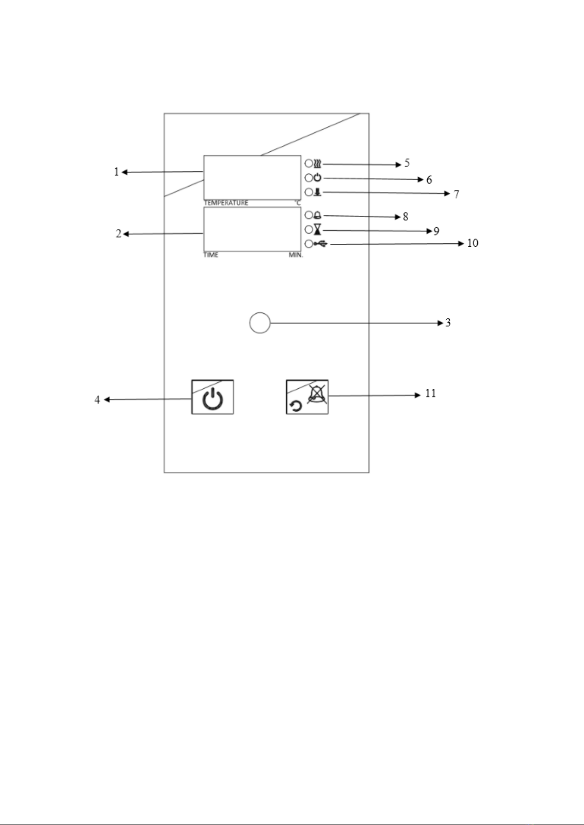
4.2 CONTROL PANEL ..........................................................................................................9
4.2.1 Explanations and Functions for Display and Control Panel........................................9
4.3 PREPARATION OF USER SETTINGS..........................................................................10
4.3.1 oP Operator Menu Parameters................................................................................11
4.4 PROGRAMMING SUMMARY........................................................................................11
WARNİNG!!.............................................................................................................................13
4.5 COMPLETION OF THE WORK.....................................................................................14
SECTION 5 ................................................................................................................................ 14
PERIODIC MAINTENANCE AND CLEANING...........................................................................14
5.1 PERIODIC MAINTENANCE...........................................................................................14
5.2 CLEANING....................................................................................................................14
SECTION 6 ................................................................................................................................ 15
DISPOSAL MANAGEMENT CONCEPT....................................................................................15
SECTION 7 ................................................................................................................................ 15
TROUBLESHOOTING...............................................................................................................15
7.1 ERROR CODES EXPLANATIONS................................................................................15
SECTION 8 ................................................................................................................................ 17
ELECTRICAL CIRCUIT DIAGRAMS .........................................................................................17
10.1 FN 300 ELECTRICAL CIRCUIT DIAGRAMS............................................................17
10.2 FN 400 ELECTRICAL CIRCUIT DIAGRAMS.............................................................18
10.3 FN 500 ELECTRICAL CIRCUIT DIAGRAMS..............................................................19
10.4 FN 400P - 500P ELECTRICAL CIRCUIT DIAGRAMS................................................20
SECTION 9 ………………………….……………………………………………………………………21
WARNING LABELS .…………………………………………………………………………………….21

4
SECTION 1
INTRODUCTION
1.1 USE AND FUNCTION
The FN Series Dry Heat Sterilizers/Ovens are designed to sterilize metal and glass materials and
heat or dry samples in laboratories. They offer excellent sterilization, drying and heating conditions.
Glass, metal and other materials can be sterilized in FN Series Dry Heat Sterilizers.
They maintain temperatures between 70°C and 250°C and keep the temperature stable within the
given tolerances.
FN 300/400/500 Dry Heat Sterilizers/Ovens provide homogeneous temperature distribution by
means of the sheet heaters placed onto three outer surfaces of the useful volume.
Differently from FN 300/400/500, inner sides of FN 400P and FN 500P are made of stainless steel
and their heaters are circular heaters which provide the homogeneity of the temperature by the
circulation fans placed on their centers.
The insulation of the Dry Heat Sterilizers/Ovens not only provides economical working conditions
but also helps to achieve the excellent homogeneity.
The FN series Dry Heat Sterilizers/Ovens provide precise operation conditions with the PID
microprocessor controlled system and with the timer. Adjustable safety thermostat offers an
additional safety.
Microprocessor control system will shut down the temperature sensor and in case of malfunctions
that may occur in the control system, alarm system will be activated and the user is warned visually
and audibly. The study data are recorded in the memory and can be transferred to external USB
memory. At the same time, unauthorized persons have been blocked permission to change
parameters with improved password menu.
The FN series dry heat sterilizer/ovens are manufactured according to the following standards,
ISO 9001:2015, ISO 13485:2016, EN ISO 14971:2012, MDD 93 / 42 / EEC (2007/47/EC), EN
60601 –1, EN 60601 –1 –2, EN 60601 –1 –6, EN 62304, EN ISO 15223 –1, EN 61000–6–3,
EN 62366 –1, EN 50419.
This device is in compliance with WEEE Regulation.
Do not operate the instrument for purposes other than main purpose.
The instrument is only to be used by authorized people after the user’s manual has been
read carefully. Only technical personnel can handle the product in case of a breakdown.

5
SECTION 2
TECHNICAL SPECIFICATIONS
2.1 TECHNICAL SPECIFICATIONS TABLE
FN 300
FN 400
FN 400P*
FN 500
FN 500P*
Temperature Range
70°C / 250°C
Temperature Sensor
Fe-Const
Control System
PID Programmable Microprocessor
Temperature set & display sensitivity
1°C
Temperature variation(100°C-150°C)
±2°C
Temperature fluctuation
±1°C
Thermostat Working Accuracy
±1°C
Timer
1 minute + 99.9 hours + Hold Position
No of shelves (standard/max.)
2/6
2/7
2/7
2/10
2/10
Safety thermostat
Gas expansion thermostat (50°C-300°C)
Power consumption
500 W
800 W
850 W
1600 W
1550 W
Power Supply
230V, 50/60 Hz
Memory
3000 data*
Useful volume
22 liters
44 liters
42 liters
120 liters
110 liters
Internal material
Anodic-
oxidated
aluminum
Anodic-
oxidated
aluminum
Stainless
Steel
Anodic-
oxidated
aluminum
Stainless
Steel
External material
Epoxy-polyester painted steel
Internal dim.s (wxdxh) mm
300x240x300
420x320x360
420x280x360
500x480x500
500x445x500
External dim.s (wxdxh) mm
555x380x460
705x475x540
705x505x540
785x630x680
790x665x680
Packing dims.(wxdxh)mm
650x470x550
790x580x615
790x580x760
870x740x860
870x740x860
Net/Packed weight
24 / 29
37 / 43
39 / 45
55 / 65
66 / 74
*Shows the number of lines for each work done. Temperature, time and if there is error code
consist of 1 line.
**Differently from EN 400 and EN 500, inner sides of EN 400P and EN 500P are made of stainless
steel and their heaters are circular heaters which provide the homogeneity of the temperature by
the circulation fans placed on their centers.
2.2 OPTIONAL ACCESSORIES
R 01 014 Al. shelf for FN 300
R 01 136 Mesh type shelf for FN 400
R 01 126 Mesh type shelf for FN 400P
R 01 135 Mesh type shelf for FN 500
R 01 111 Mesh type shelf for FN 500P
K 23 031 Shelf carrier for FN 300
K 23 047 Shelf carrier for FN 400
K 23 048 Shelf carrier for FN 400P
K 23 046 Shelf carrier for FN 500
K 23 040 Shelf carrier for FN 500P
Note: 2 pcs. Shelf carrier should be ordered for each shelf.

6
2.3 GENERAL PRESENTATION
Fıgure 1: Inner side of FN 400 P / 500 P

7
SECTION 3
INSTALLATION PROCEDURE
3.1 LIFTING AND TRANSPORT
Because of the heavy weight of the Dry Heat Sterilizer/Oven, all lifting andtransport must be carried
out using proper handling equipment. The Dry Heat Sterilizer/Oven must be supported from
underneath and never turned over.
3.2 UNPACKING
Remove the packing cardboard box and the second nylon packing around the Dry Heat Sterilizer.
The below written are provided with the instrument, please check them;
User’s manual
1 piece electrical cable
2 pieces of shelves
1 pieces of warranty
1 pieces of shelf carriers
3.3 POSITIONING
Check that no damage has occurred during transport.
Lift the dry heat sterilizer/oven underneath and carry it to its place carefully.
Balance the Dry Heat Sterilizer/Oven on the four pedestals. If necessary, provide stable
standing by adjusting the pedestal heights.
Insert the shelf carriers and then the shelves.
Check the followings,
The proposed site is suitable for users,
The dry heat sterilizer/oven does not occupy the utilisation space of others or damage them.
3.4 ENVIRONMENTAL CONDITIONS
Please pay special attention to the followings,
At most 70% of the surface area of the shelves should be used in order to obtain a uniform
temperature distribution.
Indoor use only
Temperature from 5°C to 40°C
Humidity level %80 up to 22°C
Maximum height 2000m.
Temperature range for maximum performance: 15ºC / 25ºC
1. Control panel
8. Shelf carrier holder
2. Safety thermostat
9. Shelf carrier
3. On / Off switch
10. Circulation fan
4. Ventilation hole
11. Heater
5. Shelf
12. Heater protecting sheet
6. Chamber gasket
13. Input USB
7.Mains supply inlet and the fuses
14. Door handle

8
3.5 MAINS SUPPLY
The dry heat sterilizer/oven requires 230, 50 / 60 Hz.
Please make sure that the supplied mains matches the required power ratings. If no, provide
an extra line to support.
Always plug the Dry Heat Sterilizer/Oven to properly earthed sockets.
A supply fitted with a circuit breaker should be used for protection against indirect
contact in case of an insulation fault.
3.5.1 Prior to Operation
Check the followings,
Make sure that the safety thermostat is adjusted to the temperature which is higher than the
set temperature.
Liquids are not heated in sealed containers.
The boiling points of the samples are higher than the set temperature.
The freezing points of the samples are lower than the set temperature.
The liquids which may expand during heating do not overflow from their containers.
The set temperature does not destroy the structure of the samples.
The vapours and gases which are generated during the operation are not harmful to human
health or flammable or explosive.
The instruments, which will be dried up and heated, should not be combustible and explosive,
especially please kindly check that.
IF MENTIONED WARNINGS ARE NOT CONSIDERED, NUVE WILL NOT BE RESPONSIBLE
FROM THEIR RESULTS.
SECTION 4
OPERATING PRINCIPLES
4.1 SWITCHING ON
Push on/off switch.
See that the microprocessor control system activates.
Learn the functıon of the control and display panel( Section 4.2).
Section 4.3 and section 4.4, according to the program will run and run please.

9
4.2 CONTROL PANEL
1. Temperature display
6. “Operating the program” lamp
11. Back / Alarm mute button
2. Time display
7. Data transfer lamp
3. Encoder button
8. Alarm led
4. Start / Stop button
9. “End of the program” lamp
5. Heating lamp
10. Usb lamp
4.2.1 Explanations and Functions for Display and Control Panel
01-Temperature Display
This display shows
Sterilization chamber temperature during “stand-by” and during the operation (thermometer
position),
During program preparation, the temperature setting values or the alarm setting values,
Failure codes,
EoF warning when power is interrupted,
The set temperature values and alarm values.

10
02-Time Display
This display shows the values set for time during program preparation. Also; this display shows
he time values in the control of the settings.
03-Encoder Button
The encoder button has two physical movements. The button turn clockwise and anticlockwise to
increase or decrease the temperature and time values of the program. Also, the button press for
select / confirm.
04-Start / Stop Button
Used button to start the device to operating at set values or to stop the operation.
05-Heating Lamp
The led is “on” during heating, it indicates that the heating process is carried out.
06-“Operating The Program” Lamp
A lamp indicating that the program is running as soon as the device is started.
07-Data Transfer Lamp
The lamp indicates that the records are transferred in the memory or the file is transferred during
software update.
08-Alarm Led
This led flashes when there is a warning or error on the device.
09-“End of The Program” Lamp
It is a warning lamp that indicates that the running program is finished.
10-Usb Lamp
This lamp is on when connected to a USB external memory.
The device supports up to 8 GB of external memory.
11-Back / Alarm Mute Button
This button is used to silence audible alarms in case of error and cancel the changes in the menu.
4.3 PREPARATION OF USER SETTINGS
The device has a password protected menu. The password is set to “000” when the device first
starts. Follow the below steps to change the password, update current date / time information and
access the operator's menu where other settings are made.
Wait by pressing the encoder button.

11
TEMPERATURE 0C
Lift your hand when you see "oP" on the temperature display and
again press the encoder button. If the device has a menu
protection password, password screen “oPS” will come on the
temperature display.
You enter the set password to turn the encoder button right and
left. ( The password will not be asked if the device is newly
installed.) Confirm the password by pressing the encoder button.
Observe that the parameter numbers on the temperature display
change with each pressing the encoder button. For operator
menu parameter descriptions (see section 4.3.1). You can set the
parameter values by turning the encoder button right or left on
time display.
Again press the encoder button and confirm the set value. Press
the back button to return the work screen.
4.3.1 oP Operator Menu Parameters
1: Recording Period: This time is recording period of temperature and error information.
2: Lid Alarm Time: Not used for all FN models.
3: Lid Alarm Range: Not used for all FN models.
4: Timer Set Band: When the read temperature reaches the "Set Temperature - TIMER SET
BAND" value, the time starts counting backwards.
5: Buzzer ON/OFF: The alarm sound on/off 0: OFF 1: ON
6: Date Setting - Year: Two digits are displayed the year information of date. If updating is
necessary, change.
7: Date Setting - Month: The month information of date is displayed. If updating is necessary,
change.
8: Date Setting - Day: The day information of date is displayed. If updating is necessary, change.
9: Time Setting - Hour: The hour information of time is displayed. If updating is necessary, change.
A: Time Setting - Minute: The minute information of time is displayed. If updating is necessary,
change.
B: Time Setting –Second: The second information of time is displayed. If updating is necessary,
change.
C: Date / Time Update: 0: No change 1: Update date / time according to the entered values. The
entered values are considered as current Date / Time information when 5, 6, 7, 8, 9, A parameters
are changed and B parameter is set to 1.
D: Password: The password used to enter the operator parameters. This password used when
you want to change the set values. No password if 0 is selected.
4.4 PROGRAMMING SUMMARY
You can set the steam sterilizer on stand-by. Follow the below steps to set and save the values.
Push the encoder button

12
By pushing the encoder button select SET menu.
See that second LED flashes in the temperature
display, again push the encoder button.
See the parameter flashing on the temperature
display.
By turning the encoder button set operating
temperature value.
Push the encoder button and save set value.
See the parameter flashing on the temperature
display.
By turning the encoder button set operating Set
alarm value. If the temperature is out of Set
alarm value, audible and visual alarm will be
activated.
Push the encoder button and save set value.
Turn the encoder button to the right.

13
See that second LED flashes in the time display,
again push the encoder button.
See the parameter flashing on the time display.
By turning the encoder button set operating time
value (01 minute to 99 hours 54 minutes or
Hold).
Push the encoder button and save set value.
See 'dLY' in the temperature display.
By turning the encoder button set operating
delay time value. If 'Off' is selected, heating will
start without delay. If any numerical value is
selected; After pressing Start, it starts heating
after the set delay time (01 minute to 99 hours
54 minutes).
.
Push the encoder button and save set value.
Push ‘the start button’ and start the program.
NOTE:
In order to display the set values during the operation, push the encoder button
once. The values set on the temperature display and the time display of the device
will appear for 5 seconds.
WARNİNG!!
NOTE: During the operation of the program, the time starts to count up after the instrument
has reached to the set temperature.

14
4.5 COMPLETION OF THE WORK
See that the program is over (See “End” and “End of the program lamp”).
Take the samples out. Be careful while handling the samples after the operation as they
can be hot.
Wipe the chamber surface if needed when the chamber is cold enough.
You may leave the incubator at stand-by position or switch it off.
Operating records are transferred to the usb port attached a USB memory.
NOTE :
The usb led and the data transfer led on the control panel turn on during transfer of data in
memory and the transfer process starts automatically. Do not remove external memory
from usb port without the data transfer led turn off and the audible alarm finished.
NOTE :
Records are transferred to external memory when external memory is connected to the
Usb port.
ATTENTION !!!
If the unit is in START position in case of the open door, it will keep operating
and the heaters will be over-heated. Besides, the heaters and other components
may be defected. Please be careful.
The samples may be hot after the operation, please be careful while handling
them!!
SECTION 5
PERIODIC MAINTENANCE AND CLEANING
5.1 PERIODIC MAINTENANCE
The Dry Heat Sterilizer/Oven does not require any periodical maintenance which is carried
out by the operator.
Please contact to Nüve agent for an authorised service or maintenance.
5.2 CLEANING
After unplugging the equipment and the equipment is at the room temperature, wipe down the
chamber to remove any undesirable effects of the operation, for example spillage.
You may use a soft brush to clean the chamber.
For the external body, you may use a piece of cloth. Mild detergent use is recommended to
remove difficult dust and dirt.
Protect your chamber against rust coming from outside.
PLEASE BE AWARE OF THE UNDESİRABLE EFFECTS OF THE CHEMİCALS AND BE
CAREFUL WHİLE APPLYİNG THEM.

15
SECTION 6
DISPOSAL MANAGEMENT CONCEPT
The currently valid local regulations governing disposal must be observed. It is in the responsibility
of the user to arrange proper disposal of the individual components.
Applicable local regulations for disposal have to be carefully observed.
The instruments andelectronic accessories (without batteries, power packs etc.) must bedisposed
off according to the regulations for the disposal of electronic components.
Batteries, power packs and similar power source have to be dismounted from electric/electronic
parts and disposed off in accordance with applicable local regulations.
SECTION 7
TROUBLESHOOTING
If the Dry Heat Sterilizer/Oven does not operate, check the followings,
The on/off switch is on,
The plug is plugged-in properly,
The plug is not defective,
The mains supply is present,
Fuses of the instrument are sound,
The fuse of the installation on which the plug is mounted is not defective
The incubator does not heat, check the followings,
The program is started,
The safety thermostat is adjusted higher than set temperature.
7.1 ERROR CODES EXPLANATIONS
Er1
The temperature sensor endings are broken. The error code flashes on the temperature display
and an audible alarm sounds.
Er2
An electronic failure occurs in the microprocessor. The error code flashes on the temperature
display and an audible alarm sounds.
Er3
The temperature sensor measures a temperature higher than 147°C.The error code is shown on
the temperature display and an audible alarm sounds.
Er4
The temperature sensor endings are connected in reverse. The error code flashes on the
temperature display and an audible alarm sounds.

16
EoF
This error code appears if any probable power cut causes when the sterilization phase “EoF”
flashes and the audible alarm sounds on the temperature display.
IN CASE OF ANY ERROR, THE PROGRAM İS STOPPED AUTOMATİCALLY AND
İMMEDİATELY.
PLEASE CONTACT TO AN AUTHORIZED NUVE AGENT TO SEEK TECHNICAL HELP IF AN
ERROR OCCURS.

17
SECTION 8
ELECTRICAL CIRCUIT DIAGRAMS
10.1 FN 300 ELECTRICAL CIRCUIT DIAGRAMS

18
10.2 FN 400 ELECTRICAL CIRCUIT DIAGRAMS

19
10.3 FN 500 ELECTRICAL CIRCUIT DIAGRAMS
Other manuals for FN 300
1
This manual suits for next models
4
Table of contents