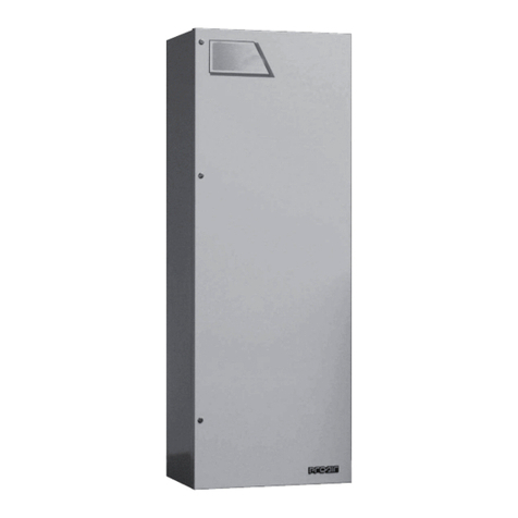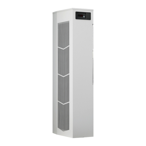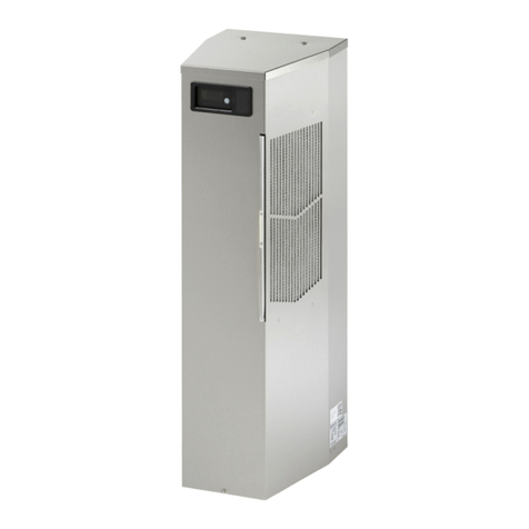
© 2023 nVent 89209669
- 2 -
NOTE: Some of the information in this manual may not apply if a special unit was ordered. If
additional drawings for a special unit are necessary, they have been inserted. Contact nVent
Equipment Protection if further information is required.
TABLE OF CONTENTS
WARRANTY AND RETURN POLICY....................................................................................................................................................................... 3
RECEIVING THE AIR CONDITIONER ..................................................................................................................................................................... 3
HANDLING AND TESTING THE AIR CONDITIONER ............................................................................................................................................ 3
HOW TO READ MODEL NUMBERS ....................................................................................................................................................................... 3
TECHNICAL INFORMATION .................................................................................................................................................................................. 4
Sequence of Operation.............................................................................................................................................................................................................. 4
Heating............................................................................................................................................................................................................................... 4
Cooling ............................................................................................................................................................................................................................... 4
Standard and Optional Component Operation ........................................................................................................................................................................ 4
Thermostat ........................................................................................................................................................................................................................ 4
Remote Access Control (optional) .................................................................................................................................................................................. 4
Head Pressure Control...................................................................................................................................................................................................... 4
Contactor ........................................................................................................................................................................................................................... 4
Overload............................................................................................................................................................................................................................. 4
Phase Monitor ................................................................................................................................................................................................................... 5
460V to 230V Transformer............................................................................................................................................................................................... 5
230V to 10V Transformer (optional)................................................................................................................................................................................ 5
a230V to 24V Transformer and Relay (optional)............................................................................................................................................................ 5
Schematics and Wiring Diagrams for Thermostat Control.................................................................................................................................................... 6
G52 Generic Schematic With Thermostats (actual unit options may vary)................................................................................................................. 6
G52 Generic Wire Diagram With Thermostats (actual unit options may vary)............................................................................................................ 7
INSTALLATION INSTRUCTIONS With Thermostats............................................................................................................................................ 8
INSTALLATION INSTRUCTIONS WITH REMOTE ACCESS CONTROL ............................................................................................................... 8
DIMENSIONAL DRAWINGS.................................................................................................................................................................................. 10
8000 BTU/Hr. With Thermostats ............................................................................................................................................................................................ 10
12000 BTU/Hr. With Thermostats .......................................................................................................................................................................................... 10
8000 BTU/Hr. With Thermostats and Heat............................................................................................................................................................................ 11
12000 BTU/Hr. With Thermostats and Heat.......................................................................................................................................................................... 11
DIGITAL THERMOSTAT CONTROLLER (OPTIONAL)......................................................................................................................................... 12
Overview.................................................................................................................................................................................................................................... 12
ENERGIZING THE CONTROLLER............................................................................................................................................................................................ 12
CONTROL STATUS INDICATION............................................................................................................................................................................................. 12
DISPLAYING AND CHANGING PROGRAM Settings.............................................................................................................................................................. 15
To view or access the settings....................................................................................................................................................................................... 15
Heat/Cool Operating Parameters ........................................................................................................................................................................................... 15
Alarm Parameters.................................................................................................................................................................................................................... 15
DISPLAYING TEMPERATURE DATA ON SCREEN.................................................................................................................................................................. 17
COMPRESSOR RESTART TIME DELAY................................................................................................................................................................................... 17
ALARM OUTPUT CONTACT .................................................................................................................................................................................................... 17
ALARM INPUT CONNECTION ................................................................................................................................................................................................. 17
PRIMARY-SECONDARY (PS) MODE ....................................................................................................................................................................................... 18
Connecting units together in Primary/Secondary mode...................................................................................................................................................... 18
Connecting units together in Lead/Lag mode....................................................................................................................................................................... 19
AIR CONDITIONER UNIT REMOTE COMMUNICATION FEATURES...................................................................................................................................... 20
USB COMMUNICATION .................................................................................................................................................................................................. 20
ETHERNET COMMUNICATION ...................................................................................................................................................................................... 20
USING HOFFMAN PC INTERFACE TOOL ............................................................................................................................................................................... 21
USB COMMUNICATION MODE ...................................................................................................................................................................................... 21
USB COMMUNICATION MODE ...................................................................................................................................................................................... 22
ETHERNET COMMUNICATION MODE .......................................................................................................................................................................... 23
REMOTE ACCESS CONTROL PIN-OUT................................................................................................................................................................................... 24
Schematic and Wiring Diagram for Remote Access Control............................................................................................................................................... 25
G52 Generic Schematic With Remote Access Control (actual unit options may vary) ............................................................................................ 25
G52 Generic Wire Diagram With Remote Access Control (actual unit options may vary) ....................................................................................... 26
DIMENSIONAL DRAWINGS.................................................................................................................................................................................. 27
G52 Generic Model Drawing With Remote Access Control ................................................................................................................................................. 27
MAINTENANCE .................................................................................................................................................................................................... 28
Compressor .............................................................................................................................................................................................................................. 28
Inlet Air Filter............................................................................................................................................................................................................................. 28
How To Remove, Clean or Install a New Inlet Air Filter......................................................................................................................................................... 28
Condenser and Evaporator Air Movers .................................................................................................................................................................................. 29
Refrigerant Loss....................................................................................................................................................................................................................... 29
F-GAS INFORMATION .......................................................................................................................................................................................... 29
Refrigerant Properties Chart (R 134a).................................................................................................................................................................................... 30
Functional Data ........................................................................................................................................................................................................................ 30
8000 BTU/Hr. Unit Characteristics ......................................................................................................................................................................................... 31
12000 BTU/Hr. Unit Characteristics ....................................................................................................................................................................................... 32
SERVICE DATA ...................................................................................................................................................................................................... 33
Components List With Thermostat ........................................................................................................................................................................................ 33
Components List With Remote Access Control.................................................................................................................................................................... 34
TROUBLE SHOOTING........................................................................................................................................................................................... 36
Basic Air Conditioning Trouble Shooting Check List - Thermostat Version........................................................................................................................ 36
Symptoms and Possible Causes - Thermostat Version....................................................................................................................................................... 37
Basic Air Conditioning Trouble Shooting Check List - Remote Access Control Version ................................................................................................... 38
Symptoms and Possible Causes - Remote Access Control Version................................................................................................................................... 39
