NVIS AVCU User manual


Advanced Video Control Unit (AVCU) User Guide 2 |
ADVANCED VIDEO CONTROL UNIT (AVCU)
USER GUIDE
Table of Contents
Welcome.............................................................................................................3
Basic Function of the Advanced Video Control Unit.............................................3
Step-by-Step Setup Procedures..........................................................................4
Configuring the AVCU............................................................................. 5
Automatic Video Detection ..................................................................................5
Navigating the AVCU Interface............................................................................5
Adjusting Brightness............................................................................................6
Setting AVCU Preferences...................................................................... 7
Using SXProg........................................................................................... 9
Firmware Upgrades.............................................................................................9
Upgrade Color Sequence..................................................................................10
Position Adjustment...........................................................................................11
Dithering Control and Configuration...................................................................12
Troubleshooting Your System ............................................................. 13

Advanced Video Control Unit (AVCU) User Guide 3| www.nvisinc.com
WELCOME
Thank you for purchasing your NVIS display system. This manual documents the operation of
your Advanced Video Control Unit (AVCU). The AVCU is video interface for the following NVIS
displays: nVisor SX60, nVisor SX111, and Virtual Binocular SX. There are additional
legacy systems that may use the AVCU as well, and the general operation should be the same
as explained in this manual.
The AVCU video interface accepts standard digital or analog video from a commercial PC
workstation andconvertsthis video informationinto the digital signals required bythe microdisplay
in your NVIS head-mounted or hand-held display device. It’s a critical component of your overall
system and this document provides an overview of how to connect, configure, and use your NVIS
display using the AVCU.
BASIC FUNCTION OF THE ADVANCED VIDEO CONTROL UNIT
The AVCU accepts the video signal from the image generator and provides the correct sync and
voltage information to the microdisplays in the head-mounted display. The AVCU design supports
multiple product configurations and as such, accommodates single and dual video input options.
The partial optical overlap configuration of the nVisor SX111 optical system requires different
viewing frustum parameters for each eye and therefore must always operate with different LEFT
and RIGHT eye images. This is explained in more detail later in the manual.
The front panel of the AVCU is shown in Figure 1.
The back panel of the AVCU is shown in Figure 2. The back panel is used to connect DC power
and the left and right input cables from a VGA video card or a DVI video card.
Power Input and Indicator
Outputs to VGA or DVI
repeater monitor
Inputs from VGA or DVI
video card
USB and RS232
Figure 1 Front Panel of the AVCU
Figure 2 Back Panel of the AVCU
LCD
Power On/Off
Selection Buttons
Left and right outputs to
the head-mounted display
Left and right outputs to
the head-mounted display

Advanced Video Control Unit (AVCU) User Guide 4| www.nvisinc.com
STEP-BY-STEP SETUP PROCEDURES
All NVIS products ship with the necessary cabling for basic monoscopic (non-stereo) operation.
Figure 3 illustrates the setup steps for connecting your computer to the AVCU and for cabling the
HMD to the AVCU (dual-input configuration shown).
Figure 3 Setup Steps
Connect NVIS display
cables to the AVCU. AVCU
connectors are color coded
white or black and should
match display connectors.
Plug the power cable
(which includes the
universal power supply)
into the AVCU and into
110-220V AC source.
Connect your video
cable(s) to the computer
and to the AVCU.
Connect an optional
external monitor from the
AVCU (two external
monitor ports are provided
on the back of the AVCU).
Connect an optional
motion tracker. (Note: You
might need to take
additional steps to con-
figure your motion tracker.
Please consult your motion
tracker user manual for
instructions.)
Power on the AVCU.
For the headset to operate properly, you need to make
sure that your display is set for 1280x1024 resolution
at 60 Hz. Please refer to Figure 4 for an example of
what your display settings should look like.
Figure 4 Setting the Display
Properties

Advanced Video Control Unit (AVCU) User Guide 5| www.nvisinc.com
CONFIGURING THE AVCU
AUTOMATIC VIDEO DETECTION
Input video detection is built into the AVCU and is enabled by default. The AVCU has circuitry
that can detect several video input configurations. These include the following:
VGA mono (left or right)
DVI mono (left or right)
VGA stereo
DVI stereo
Mixed stereo (using VGA and DVI video signals to achieve a stereoscopic set up).
The default video detection setting may not work for all situations. It may be required in rare
instances, with older video generators, third-party video splitters and/or VGA cables with missing
pins, to disable the automatic detection setting. It is recommended that VGA cables with all 15
pins be used with the AVCU. Instructions for disabling the video detection circuit can be found
later in this guide.
NAVIGATING THE AVCU INTERFACE
The front of the AVCU has an LCD screen that displays various settings and messages. Next to
the LCD reside three buttons used for navigation and toggling settings (Figure 5).
Upon powering the AVCU and pressing the power button located on the left side of the front panel,
the LCD will display the AVCU product name as well as the version number of the firmware.
The “enter” button cycles through four information banners. The information displayed in these
banners is designed to help the user configure the input video signals. The first banner is
mentioned above, displaying the product name and firmware version. The second banner
displays video timing information (Figure 6 and Figure 7). A third banner displays which various
video inputs are detected (Figure 8). The last banner shows the current monitor out configuration
for a stereo setup (Figure 9).
LCD Control Panel
Display
Left and Right
Selection Buttons
Enter Button
AVCU-W
Version 1.4
t
Figure 5 AVCU Navigation Buttons

Advanced Video Control Unit (AVCU) User Guide 6| www.nvisinc.com
Figure 6: First Video Timing Information Display
An example of the LCD displaying the video timing information is shown in Figure 6. The
information indicates that the left channel is currently receiving a 1280x1024 resolution video
signal operating at 60 Hz. In addition, the letter “D” at the end of the text string indicates that the
signal is digital. In the case of an analog signal, the letter “A” will be displayed in its stead (Figure
7). The “Mono Clone” message on the right channel indicates that no video signal was detected
on the right eye. The AVCU is currently repeating the left video signal to the right eye.
Figure 7: Second Video Timing Information Display
If a stereoscopic setup is being used, timing information for both eyes will be displayed.
Figure 8 shows and example of the video detection banner. In the example, a DVI signal is detect
on the left channel, as indicated by the “x”.
Figure 8: Video Detection Display
The monitor output settings for the two monitor outs can be viewed by pressing the Enter button
until the corresponding banner is displayed. An example of the monitor out settings banner is
shown in Figure 9.
Figure 9: Monitor Out Settings Display
The banner is currently indicating the monitor out setting in the case of a stereoscopic setup. The
VGA monitor out will repeat the left eye, and the DVI monitor out will also repeat the left eye.
ADJUSTING BRIGHTNESS
On standard AVCU products (AVCU-S), pressing the +/- buttons from the main menu adjusts the
brightness of the display. On wide FOV products (AVCU-W) the brightness controls are disabled.
The +/- buttons will not do anything.
L:1280x1024x60D
R:Mono Clone
Stereo Mon Out
VGA: L DVI: L
L:1280x1024x60A
R:Mono Clone
VGA( ) VGA( )
DVI(X) DVI( )

Advanced Video Control Unit (AVCU) User Guide 7| www.nvisinc.com
SETTING AVCU PREFERENCES
The AVCU can detect video inputs in most situations. However there are instances when manual
configuration is required. This is particularly common when running video through active
extenders, and when using video distribution amplifiers. In addition to disabling the video
detection circuitry, several other options can be changed in the AVCU preferences.
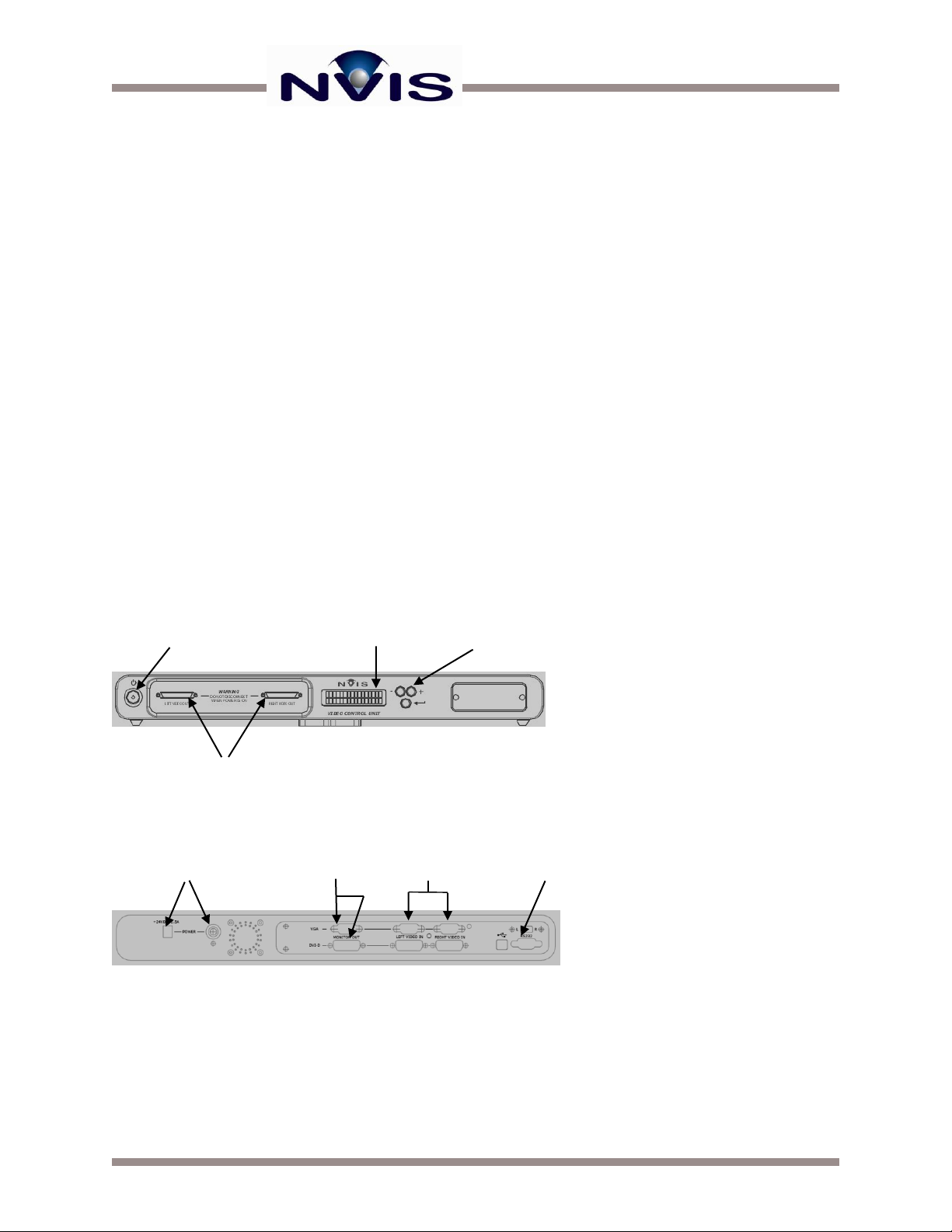
You can easily change the AVCU preferences by using the selection buttons on the front of the
AVCU:
First, make sure the AVCU is powered OFF.
Simultaneously hold down the - and + selection buttons, and then press the Power button.
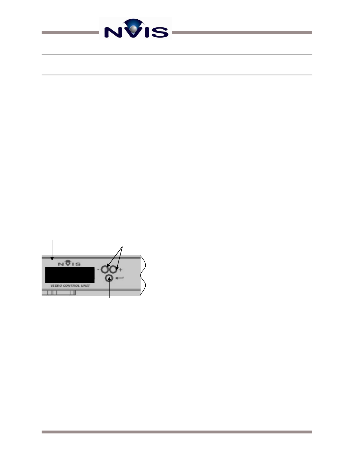
You should then see the Preferences label on the LCD control panel display (Figure 10).
Figure 10: The Preferences Label
Press the +, -, or Enter button to continue.
You are now in the Preferences menu. Navigation through the Preferences menu is done by
pressing +/- buttons to scroll through the various settings. You can hit the Enter button to change
a setting. In Figure 11, the DAC output setting is selected. The pointy brackets on the first line
of the LCD indicates that there are more options available by pressing the “+“ button.
Figure 11: DAC Output Selected
Once the desired setting has been selected to be changed, pressing Enter will allow changes to
the setting.
Once enter is pressed, square brackets will appear on the first line of the LCD display, and pointy
brackets will appear on the second line. Use the +/- buttons to select the desired option and press
enter again to change the setting to the selected option.
There are several settings that can be changed on the AVCU. These include the following 4
settings:
DAC OUTPUT –this setting controls the digital to analog converter on the AVCU for the VGA
monitor out. The options are:
Auto –attempt to automatically detect whether a monitor is connected to the VGA monitor out
and turn the DAC on/off accordingly.
Always On –the DA converter is always turned on.
Preferences
Press Any Key
DAC Output >
ON

Advanced Video Control Unit (AVCU) User Guide 8| www.nvisinc.com
Always Off –the DA converter is always turned off.
In cases when power savings is an issue (battery-powered options) it might be desirable to have
the setting on Auto or Always Off. The default is Always On.
VIDEO DETECT –this setting turns the video detection circuitry on and off. The options are:
Auto –Attempt to detect incoming video automatically.
VGA Mono –Always turn on the VGA left channel and repeat the video signal to the right eye.
VGA Stereo –Always turn on the VGA left and VGA right channels.
When the older VGA cables and/or video distribution devices are used, plug and play may be
disabled on the video inputs for analog signals. If this is the case, the automatic video detection
circuitry will fail to detect incoming video signals. To set up the video inputs correctly, one of the
manual analog settings will need to be used toforce the video channels to accept the VGA signals.
STEREO MON OUT –The setting changes how the monitor outputs will be configured during
a stereoscopic configuration. The options are:
VGA: L DVI: L –The left eye is always repeated on VGA monitor out and the DVI monitor out.
VGA: R DVI: R –The righteyeisalwaysrepeated on the VGA monitor out and the DVI monitor out.
VGA: L DVI: R –The left eye is repeated on the VGA monitor out and the right eye is repeated
on the DVI monitor out.
VGA: R DVI: L –The right eye is repeated on the VGA monitor out and the left eye is repeated
on the DVI monitor out.
AVCU TYPE –This is a factory setting and should not be changed.

Advanced Video Control Unit (AVCU) User Guide 9| www.nvisinc.com
USING SXPROG
The Advanced Video Control Unit includes an RS-232 port for use with the SXProg software
available from NVIS. This software allows users to perform the following functions:
Firmware upgrades
Color sequence up-grades
Adjust color depth and dithering functions
FIRMWARE UPGRADES
As a general rule, if your system is functioning properly, there is most likely no need to upgrade.
NVIS technical support will provide you with the latest and most appropriate firmware version if it
is determined that an upgrade can resolve an issue. Before starting, you will need to know the
location of the latest microcode. By default, two files with the .hex extension are placed in the
following directory/folder path (or similar based on your specific installation):
C:\Program Files\SXprog\User\Code\
Select both the AP.hex and BP.hex files separately using the appropriate tab.
To begin the upgrade:
Make sure your AVCU is powered off.
Connect the cable to a 9-pin RS-232 port on your PC and the RS-232 connector on the
AVCU.
Launch the SXprog application.
Click on the Program tab at the top of the screen shown in Figure 12.
Click on Program Board. You will see a small window with a progress meter.
Turn on the AVCU so that the transfer can begin. The system will proceed to transfer the two
new files to the AVCU.
When the hourglass pointer changes back to an arrow pointer (and not before), turn the unit
off.
Close the SXprog application.
You can now turn the display back on, and the new firmware will be operational.

Advanced Video Control Unit (AVCU) User Guide 10 | www.nvisinc.com
Figure 12: Selecting the Program Tab
UPGRADE COLOR SEQUENCE
Updated color sequences are available directly from NVIS. Improvements in color sequences can
have noticeable effects on the performance of the HMD display. These improvements include:
Reduced color breakup
Reduced color sequencing artifacts
To update the color sequence for your system:
Connect the cable to a 9-pin RS-232 port on your PC and the RS-232 connector on the
AVCU.
Launch the SXprog application.
Before starting, make sure you have the new color sequence file loaded into the following
directory/folder path (or similar, based on your specific installation):
C:\Program Files\SXprog V3_3\User\Sequences
Turn on the AVCU and wait approximately 5 seconds, then click on Connect. You will see
the screen shown below in Figure 13.
The active sequence will be highlighted with an asterisk next to it in the box located at the
center of the screen.
Click on Send Sequence. The Select File dialog box will appear, allowing you to select the
new sequence.
After you select the correct file, the system will proceed to download this file to the AVCU.

Advanced Video Control Unit (AVCU) User Guide 11 | www.nvisinc.com
Figure 13: The Connection Tab
POSITION ADJUSTMENT
You might need to adjust horizontal centering of the image that appears, depending on which
video format you are using. Pixel screen position is adjusted for standard analog video at the
factory (unless otherwise requested). If pixel screen position is improperly adjusted, horizontal
wrapping can occur.
To move the displayed image left or right:
Click on the Picture tab to display the dialog box shown in Figure 14.
Adjust the IN_HSTART value to shift the horizontal center left or right.
Figure 14: The Picture Tab

Advanced Video Control Unit (AVCU) User Guide 12 | www.nvisinc.com
DITHERING CONTROL AND CONFIGURATION
The most recent NVIS products include enhanced capabilities to manipulate the color
performance to reduce color sequential artifacts (the LCOS is a reflective, color sequential
display).
The LCOS micro-displays used in NVIS products are monochrome reflective devices. Color is
provided through the illumination source—in the case of NVIS products, this is accomplished with
a diffuse RGB LED source. The LCOS pixels exist in one of two states –on or off. The display
can adjust the intensity of each color on a per pixel basis through temporal modulation of the pixel
–turning it on and off in rapid succession to achieve the correct intensity of each color from the
LED. This occurs per color, per frame, at 60 Hz.
In some applications, users may perceive dynamic false contouring (DFC) in regions of the
database that contain transitioning color gradientsor textures with many graylevels. This situation
is caused by the time delay between modulating for the first and last bit of a given color. By
truncating the bit depth for each pixel, you can reduce this time delay and the effects of DFC.
The dithering hardware available in the current generation of NVIS products contains
enhancements to boost the color depth with an algorithm that operates on a pixel-by-pixel basis,
requiring no frame store (and therefore, no latency). This allows the hardware to effectively
“reclaim” the bit color depth that is lost.
All dithering-capable units are set to 4 bits per color (most significant), and 4 bit dither boost for
an effective 8 bit color depth. To view or change these settings, use SXprog:
Launch the SXprog application while the NVIS unit is ON, and the computer is connected to
the VCU via the included 9-pin RS-232 serial cable (straight through).
Click Connect.
When you are connected, click on the Settings tab.
You will see the Settings dialog box shown in Figure 15.

Advanced Video Control Unit (AVCU) User Guide 13 | www.nvisinc.com
Figure 15: The Settings Tab
If these options are grayed out, this means that your hardware does not support dithering, but it
can be upgraded.
Contact NVIS for more information at support@nvisinc.com. Valid settings for the dithering
configuration:
Use the full 8 native bits per color, with no dithering
Truncate down to 6 native bits per color, with 2 bit dither boost
Truncate down to 4 native bits per color, with 4 bit dither boost
Once you’ve set the dithering configuration, you need to go to the Sequence screen to select the
appropriate color sequence for your dithering configuration.
Click the Connection tab. The window from Figure 13 should appear, showing the sequences
currently loaded on your AVCU. The appropriate color sequences for the valid dither settings
listed on the previous page are respectively:
48212 ab smooth asic v2_0.seq (8 bit sequence w/ no dithering)
48251 ab smooth 666 v1_0.seq (6 bit sequence w/ 2 bit dithering)
48252 ab smooth 444 v1_0.seq (4 bit sequence w/ 4 bit dithering–default)
TROUBLESHOOTING YOUR SYSTEM

Advanced Video Control Unit (AVCU) User Guide 14 | www.nvisinc.com
This section lists common setup or configuration problems that may cause the NVIS display to
malfunction. If you experience problems that are not listed or not resolved after consulting this
section, please call or e-mail NVIS.
LEFT and/or RIGHT input not detected. The Advanced Video Control Unit is designed to
automatically detect and communicate with modern video cards, but detection is dependent on
several factors including your driver version, cable length, and intermediate video hardware
(extenders or splitters).
Analog video configuration issues can result from plug-and-play information not being
received from your video hardware. This can happen if your video cable is not transmitting
data on pin-9, or if you’re going through a video distribution amplifier (i.e., splitter). Longer
VGA cables often do not contain pin-9. In these cases you will need to force the AVCU to
VGA mode. There are two such modes depending if you have a single input or dual.
Consult Configuring the AVCU for more information.
Digital video configuration issues should be rare, and usually can be addressed by
changes made in your video hardware ‘advanced setup’ configuration. Rebooting your
PC with the connections made and the AVCU powered ON will most likely solve the
problem otherwise.
Monitor output not working. The monitor output will not function if the input video is not
recognized as 1280x1024 @ 60 Hz (SXGA) in analog or digital format. The LCD readout will
indicate if the input format is recognized as 1280x1024. Any other format will not be transmitted
to the repeated monitor.
Images do not appear in stereo. This only applies to configurations with dual inputs, and these
images are rendered for the LEFT and RIGHT eyes. Make sure the LEFT and RIGHT HMD
cables are connected to the correct input connector on the AVCU. Also check the LCD readout
to make sure both eyes are receiving an input signal. Both eyes can be operational with a single
input if the second input is not recognized.

NVIS, Inc.
11495 Sunset Hills Road, Ste. 106, Reston, VA 20190
www.nvisinc.com ● 571-201-8095
Table of contents
Popular Server manuals by other brands

Compaq
Compaq AlphaServer 1200 user guide

Helwett Packard
Helwett Packard ProLiant XL675d Gen10 Plus user guide

Dell
Dell Active Fabric Manager Deployment guide

Compaq
Compaq BL10e - HP ProLiant - 512 MB RAM Appendix

NEC
NEC Univerge SV8100 Features and specifications manual

IBM
IBM System x3400 Type 7975 user guide

HP
HP LC2000r - NetServer - 128 MB RAM installation guide

Dell
Dell PowerEdge C8000 Getting started

IBM
IBM eserver xSeries 350 installation guide

Supermicro
Supermicro SBI-7228R-T2F user manual

Netscape
Netscape NETSCAPE DIRECTORY SERVER 6.2 - GATEWAY... installation guide

Avaya
Avaya S8300 Series Installation quick reference