OCEAN PRESENCE AquariCamOPT-12HD User manual

OCEAN
PRESENCE
Technologies
Underwater IP Camera System
OPT-12HD User’s Manual
Version 2.1
AquariCam™
Model OPT-12HD
Ocean Presence Technologies ©2010-2013

AquariCam OPT-12HD User’s Manual Version: 5/29/13
Ocean Presence Technologies Copyright ©2010-2013 Page 2
NOTICE TO USERS
Copyrights ©2010-2013 Ocean Presence Technologies.
All rights reserved.
This manual or the software described
herein, in whole or in part, may not be
reproduced, translated or reduced to any
machine-readable form without prior written
approval from Ocean Presence
Technologies.
OCEAN PRESENCE TECHNOLOGIES AND AXIS
CORPORATION PROVIDES NO WARRANTY WITH
REGARD TO THIS MANUAL, THE SOFTWARE OR
OTHER INFORMATION CONTAINED HEREIN AND
HEREBY EXPRESSLY DISCLAIMS ANY IMPLIED
WARRANTIES OF MERCHANTABILITY OR
FITNESS FOR ANY PARTICULAR PURPOSE WITH
REGARD TO THIS MANUAL, THE SOFTWARE OR
SUCH OTHER INFORMATION. IN NO EVENT
SHALL OCEAN PRESENCE TECHNOLOGIES NOR
AXIS CORPORATION BE LIABLE FOR ANY
INCIDENTAL, CONSEQUENTIAL OR SPECIAL
DAMAGES, WHETHER BASED ON TORT,
CONTRACT, OR OTHERWISE, ARISING OUT OF
OR IN CONNECTION WITH THIS MANUAL, THE
SOFTWARE OR OTHER INFORMATION
CONTAINED HEREIN OR THE USE THEREOF.
Ocean Presence Technologies reserves the right to
make any modification to this manual or the
information contained herein at any time without
notice.
The software described herein may also be governed
by the terms of a separate user license agreement.
•“UWIP,” “Underwater IP Camera”,
“AquariCam” and “OceamCam” are
trademarks of Ocean Presence
Technologies.
•Microsoft, Windows, Internet Explorer and
MS-DOS are registered trademarks of
Microsoft Corporation in the United States
and/or other countries.
•Java is a trademark of Sun Microsystems,
Inc. in the United States and other countries.
•Intel and Pentium are registered trademarks
of Intel Corporation or its subsidiaries in the
United States and other countries.
•Adobe, Acrobat and Adobe Reader are
trademarks of Adobe Systems Incorporated
in the United States and/ or other countries.
All other company and product names are trademarks
or registered trademarks of the respective companies
or their respective makers.
Indicates potential electrical
hazard. Please handle with care
and observe all proper operations
and warnings.
If you have any questions about this
product, you may call:
Ocean Presence Technologies at:
831-426-4678
or Write to:
Ocean Presence Technologies
326 Pacheco Ave.
Santa Cruz, CA 95062

AquariCam OPT-12HD User’s Manual Version: 5/29/13
Ocean Presence Technologies Copyright ©2010-2013 Page 3
TABLE OF CONTENT
1.0 SHIPPED COMPONENTS ..................... 4
2.0 QUICK START....................................... 4
2.1 Configuring the Network ......................... 4
2.2 Deployment Testing................................ 5
2.3 Using the Camera .................................. 6
2.3.1 View Size................................. 6
2.3.2 Stream Profile .......................... 6
2.3.3 Zoom bar ................................. 6
2.3.4 Focus Bar ................................ 6
2.3.5 AMC Viewer Toolbar ................ 6
3.0 SYSTEM DESCRIPTION........................ 7
3.1 Camera System...................................... 7
3.2 Housing.................................................. 7
3.3 Power & Network Subsystems................ 7
3.4 Moisture Purging System........................ 8
3.5 Buoyancy Control ................................... 8
4.0 OPERATIONS ....................................... 8
4.1 Hardware Assembly ............................... 8
4.2 Camera/Network Software...................... 9
4.2.1 Software Installation ................. 9
4.2.2 Axis Media Control Viewer........ 9
4.2.3 Non-Windows Browsers ......... 10
4.2.4 Configuring the Camera ......... 10
4.2.5 Camera Orientations .............. 10
4.2.6 PTZ Functions........................ 10
4.2.7 White Balance........................ 11
4.2.8 Image Transmission ............... 11
4.2.9 Axis Camera Companion........ 11
4.2.10 Camera Recording List........... 11
4.2.11 Continuous Recording............ 12
5.0 PRE-DEPLOYMENT TESTING ............ 12
5.1 Camera/Network Tests ......................... 12
5.2 Final Check-out .................................... 12
6.0 CARE & MAINTENANCE..................... 13
6.1 Opening the Housing............................ 13
6.2 Closing the Housing ............................. 13
6.3 Above Water Maintenance.................... 13
6.4 O-Ring Greasing Technique ................. 14
6.5 Below Water Maintenance .................... 14
6.6 Periodic Maintenance ........................... 14
7.0 APPENDIX........................................... 15
7.1 Warranty .............................................. 15
7.2 Accessories (Optional).......................... 15
7.3 Replacement Parts ............................... 15
7.4 Camera Specifications.......................... 16
7.5 Housing Specifications ......................... 16
7.6 Mounting the Camera ........................... 17
7.7 Internal Camera Connections ............... 17
7.8 Underwater Cable Wiring...................... 17

AquariCam OPT-12HD User’s Manual Version: 5/29/13
Ocean Presence Technologies Copyright ©2010-2013 Page 4
SHIPPED COMPONENTS
1.0 QUICK START
The AquariCam Underwater IP camera
system (UWIP) has been designed to
simplify installation and deployment.
1.1 CONFIGURING THE NETWORK
The AquariCam is ready to be used out of
the box and is network ready. Configuration
software is included in the Installation CD
and should be downloaded and installed
into a Windows computer.
The AXIS P1357 can be used with most
standard operating systems, and supports
Microsoft Internet Explorer 5.x or later,
Netscape 7.x or later and Mozilla 1.4 or
later.
The standard system includes a power
supply and an underwater Power-over-
Ethernet (PoE) cable. The PoE connector
should be attached to the housing and the
cable stress relief sleeve lightly tightened.
To connect to the network, attach the other
end of the PoE cable to the OUT port of the
power supply. A standard Ethernet cable
can then be attached from the IN port of the
power supply to a router, computer or
Internet modem.
Once all network cables have been
attached, you can apply power to the
system. This begins the camera “booting”
process taking about a minute. To install the
camera on your computer, insert the install
disk and download the Axis IP Utility. Once
it is installed, the camera and its IP address
will become visible.

AquariCam OPT-12HD User’s Manual Version: 5/29/13
Ocean Presence Technologies Copyright ©2010-2013 Page 5
Double click on the camera to activate it in a
Windows browser. The first time that this
camera is used will display the Configure
Root Password.
THE SYSTEM HAS BEEN RECONFIGURED TO
ACCEPT THE ROOT PASSWORD OF “ADMIN.”
To set the password for the root
(administrator) user:
1. Enter a password and then re-enter it to
confirm the spelling. Click OK.
2. The ‘Enter Network Password’ dialog will
appear. Enter the User name: root.
3. Enter the password as set above, and
click OK. If the password is lost, the
cameras must be reset to the factory
default settings.
1.2 DEPLOYMENT TESTING
The camera can be deployed while the
network is operational. This will allow the
monitoring of any leakage.
DO NOT PLUG IN OR REMOVE THE
HOUSING POE CONNECTOR WHILE
UNDERWATER WHEN THE POWER
IS ON!
The camera is slightly negatively buoyant.
Weights can be added to decrease the
buoyancy. Attach weights to each side of
the housing using the metal bar and plastic
cable ties.
It is advisable to test the system in fresh
water prior to saltwater deployment. If this is
not possible, lower the camera into the
water with the camera pointing vertical and
the network active.
If a perfect o-ring seal has not been
obtained, fogging or condensation will soon
appear on the inside.
A submergence test can also we performed
without power applied. Lower the system to
a depth of 10 feet and then remove it for
visible inspection for leaks. If possible, test
the system again at a depth of 30 feet for 15
minutes.
IF ANY MOISTURE IS SEEN ON THE
TOP OF THE PORT, REMOVE THE
SYSTEM FROM THE WATER
IMMEDIATELY!
If moisture is seen on the top inside of the
port, either the O-ring was not properly
sealed or additional moisture removal may
be required. If a dry system cannot be
obtained, please contact the manufacturer
for assistance.

AquariCam OPT-12HD User’s Manual Version: 5/29/13
Ocean Presence Technologies Copyright ©2010-2013 Page 6
1.3 USING THE CAMERA
Enter the IP address into Windows Internet
Explorer and the AMC Live View page will
be displayed. You may be requested to
enter a user name and password.
1.3.1 View Size
Scales the image down to
800 pixels wide or to full
scale. Only available in
Motion JPEG.
1.3.2 Stream Profile
The drop-down list allows
you to select a
customized or pre-
programmed stream
profile on the Live View
page. Stream profiles are
configured under Video &
Audio > Stream Profiles
1.3.3 Zoom bar
Click a position directly on the zoom bar to
zoom all the way to the new position in one
movement or click the arrows at the ends of
the bar to zoom in steps.
1.3.4 Focus Bar
Click a position directly on the focus bar to
set focus at a new position in one
movement or click the arrows at the ends of
the bar to change the focus in steps.
1.3.5 AMC Viewer Toolbar
AXIS Media Control) is available in
Microsoft Internet Explorer only. See AXIS
Media Control (AMC), on page 12 of the
Axis P1357 manual for more information.
AMC displays the following buttons:
The Play/Stop button starts and
stops the live video stream.
The Snapshot button saves a
snapshot of the video image on
display. The Snapshot function
and the target directory for
saving snapshots can be
configured from the AMC Control
Applet in the Windows Control
Panel.
Click the View Full Screen
button to make the video image
fill the entire screen area. Press
Esc (Escape) on the computer
keyboard to exit full screen, or
right-click and select the option
to exit.
Click the Record button to start a
recording directly from the Live
View page. The recording is
saved in the folder specified in
the Recording tab in the AMC
Control Applet. Note that this
button is only available when
viewing with AMC.

AquariCam OPT-12HD User’s Manual Version: 5/29/13
Ocean Presence Technologies Copyright ©2010-2013 Page 7
2.0 SYSTEM DESCRIPTION
The AquariCam consists of three major
subsystems:
1) Camera
2) Housing
3) Power & Network
2.1 CAMERA SYSTEM
The AquariCam employs a full high-
definition 1080i camera that has been
designed for 24x7 operations.
2.2 HOUSING
The AquariCam housing has been specially
designed and manufactured for the Axis
P1357 IP camera. Model OPT-12HD has
been designed to a working depth of 180
feet. Other models are available for greater
working depths.
The housing uses a specially designed
acrylic port. Care needs to be exercised
when cleaning as the surface could be
scratched.
The housing features cable stress relief.
Pairs of circular o-ring are used to insure a
more reliable seal. The cylinder is free of
attached components and can be
completely removed exposing the camera
and components.
The housing has been specially designed to
protect the electronics from small amounts
of water in the unlikely event of an
improperly seated o-ring.
2.3 POWER & NETWORK SUBSYSTEMS
Power-over-Ethernet (PoE) has the ability to
carry both data and power over a single
Cat5 cable. The underwater PoE connector
can be attached or removed underwater. A
stress relief sleeve is also used.
The system employs a PoE power supply
(PoE injector). A standard Ethernet Cat5
network cable connects to a local area
network (router) and then to the Internet.

AquariCam OPT-12HD User’s Manual Version: 5/29/13
Ocean Presence Technologies Copyright ©2010-2013 Page 8
A 110/240 VAC power supply is
used to deliver 48 VDC to the
camera through the PoE cable.
DO NOT PLUG IN OR REMOVE THE
HOUSING POE CONNECTOR WHILE
UNDERWATER WHEN THE POWER
IS ON!
SYSTEM OPTIONS
2.4 MOISTURE PURGING SYSTEM
To ensure the best operation of the camera,
moisture inside the housing needs to be
removed. The use of silica drying bags is
used. If the housing is opened, especially in
high humidity environments, fresh silica
bags may need to be replaced.
2.5 BUOYANCY CONTROL
The camera is slightly negatively buoyant.
Weights can be added to further decrease
the buoyancy. Standard dive weights can be
attached to the stainless steal bars on each
side of the housing for buoyancy control.
The amount of weight is based on the surge
conditions of each deployment.
Weights should not be used for permanent
placement or in high surge. Standard lead
dive weights can be used. Attach weights to
the metal bars on either side of the housing.
3.0 OPERATIONS
3.1 HARDWARE ASSEMBLY
The camera system is shipped completely
assembled and ready for operation. The
PoE injector is also ready for use.
Attach the PoE cable to the camera using
the underwater connector. Lightly tighten
the stress relief sleeve.
Attach the other end of the PoE cable to the
OUT port of the power injector.
Attach the Ethernet cable to the network
with a CAT5 cable (not supplied) and the IN
port of the PoE injector.
Once both network connectors are
attached, plug the power into a 110/240
VAC source.
The system provides for the removal of
moisture from inside the housing with the
use of silica bags. Weights can be attached
to either side of the housing using the
vertical metal bars.
Once the underwater PoE network cable
has been attached, you can be apply power
to the system. The camera will initially
display the amber network light for a few
seconds and then the green power lights
will be displayed.
This begins the camera “booting” process
taking about one minute. After a few
seconds, the green network light will
illuminate, indicating that the network
connection was successful.

AquariCam OPT-12HD User’s Manual Version: 5/29/13
Ocean Presence Technologies Copyright ©2010-2013 Page 9
3.2 CAMERA/NETWORK SOFTWARE
The camera comes with a full set of features
including, Internet server, image capture, E-
mail and FTP image transmission, two-way
audio, motion detection, user security and
many more.
3.2.1 Software Installation
To install the camera on your computer,
insert the install disk and download the Axis
IP Utility.
Once it is installed, the camera and its IP
address will become visible.
The use of DHCP insures that an IP
address will be assigned that works with the
active network. Once the camera is
configured, the IP address can be set to a
static address for ease of future use. See
Basic TCP/IP Settings menu under Basic
Configurations.
At this point, the camera can be accessed
either by selecting the camera in the IP
Utility Program or by entering the IP
Address into a browser window.
Start the Web browser on the computer and
type the IP address of the camera in the
URL box.
3.2.2 Axis Media Control Viewer
The AMC viewer toolbar is available in
Microsoft Internet Explorer only. See AXIS
Media Control.
Full Screen Display
Click the View Full Screen button and the
video image will fill the entire screen area.
No other windows will be visible. Press Esc
(Escape) on the computer keyboard to
cancel full screen view.
Snap Shots
To record an image, click on this icon. The
images are saved in My Documents folder
under AXIS Media Control – Snapshots.
Video Stream
This button can start or stop the video
stream.
Recording Video
The button is used to record the current
(H.264/M-JPEG) video stream. The location
where the image file is saved can be
specified using the AMC control panel. To
enable recording, Select Live View Config >
Viewer Settings > Enable recording button.
Video can be recorded by selecting this
icon. The button will turn red while
recording. Select it again and the video
recording will stop. The video are saved in
My Documents folder under AXIS Media
Control – Recordings.

AquariCam OPT-12HD User’s Manual Version: 5/29/13
Ocean Presence Technologies Copyright ©2010-2013 Page 10
3.2.3 Non-Windows Browsers
The AMC viewer toolbar is only available in
Microsoft Internet Explorer. On other
browsers that do not support Active-X,
QuickTime can be used to view the camera
and to record video streams.
Motion-JPEG can be viewed on all browsers
including those that do not support AMC but
video cannot be recorded. To record video
on non-Windows browsers such as Firefox
or Safari, the video format must be set to
H.264.
QuickTime is used with H.264 only. Note
that in the settings for Video & Image >
Advanced > H.264, the Video object type
must be set to Simple which sets the coding
type to H.263, as used by e.g. QuickTime.
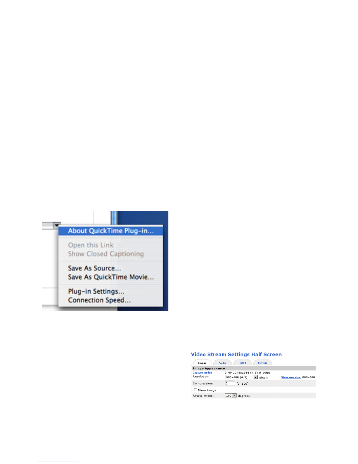
To record video using QuickTime, pull down
the menu in the lower right-hand corner of
the view screen.
3.2.4 Configuring the Camera
The camera can be remotely administered
to configure a wide range of operations. The
“Camera” settings menu is divided into
common functions, picture adjustments,
day/night operations, H.264 settings and
motion JPEG settings. (See Axis Users
Manual for a complete discussion)
The Camera settings can be set to either
H.264 or Motion-JPEG video transmission.
With adequate light, processing power and
bandwidth, Motion-JPEG and H.264 both
produce sharp images with smooth motion.
When light is reduced, Motion-JPEG video
retains a high quality image but reduces the
bandwidth by dropping frames causing a
rougher motion.
Under similar conditions, H.264 maintains
smooth motion but the video may become
corrupted reducing image quality and
introducing artifacts. This also may occur
when bandwidth is restricted as in the case
of dial-up connections.
Motion-JPEG generally requires between 4-
16 times more hard disk storage than H.264
video in order to produce similar visual
quality. H.264 requires more processing
power than Motion-JPEG. As disk space is
getting cheaper and easier to distribute and
processors are getting faster, the
importance of this consideration is
decreasing as time passes.
The camera is initially set to M-JPEG video.
The Default Video format can be changed in
the Live View Layout Configuration menu.
3.2.5 Camera Orientations
The camera can operate in three
orientations: desktop, wall or upside down
(ceiling). It is initially set to desktop or
upright.
The rotation of the video stream can be set
in the Video & Audio menu under the Basic
Configuration Instructions. This menu is
also used to set the Image Resolution and
White Balance.
3.2.6 PTZ Functions
You can pan within the full image using a
smaller zoom window. The smaller window
is first defined.
The example above has configured a 800 x
600 pixel image within a 3 mega-pixel
image (2048 x 1536).

AquariCam OPT-12HD User’s Manual Version: 5/29/13
Ocean Presence Technologies Copyright ©2010-2013 Page 11
Defined zoom windows can be moved
around using the on screen arrow or the
slider controls to the right and below of the
image.
3.2.7 White Balance
Water absorbs the color spectrum removing
the “reds” first. The camera’s white balance
can be used to correct for this color
imbalance.
The Video & Audio > Camera Settings page
provides access to advanced image settings
Select one of the options from the drop-
down list to set the white balance window
properties. Select Custom in the White
balance drop-down list to manually
increase the Red gain to warm the image.
3.2.8 Image Transmission
You can send a still image from the camera
as an E-mail attachment or to an FTP
server. The email is can be triggered by an
external sensor, a built-in activity detection
function or a manual trigger.
Enter the host names or addresses for your
primary and secondary mail servers in the
fields provided to enable event and error
email messages from the AXIS P1357 to
predefined addresses via SMTP (Simple
Mail Transfer Protocol).
You can also send still images sequentially
for a determined period before and after the
trigger to an FTP server, or send them
periodically.
3.2.9 Axis Camera Companion
Axis Camera Companion software is
included free of charge. It can be used to
access up to 16 cameras. A user tutorial is
also available:
http://www.axis.com/products/cam_compani
on_software/video/user_tutorial.htm
3.2.10 Camera Recording List
Recorded videos are listed on the
Recordings > List page. The list shows each
recording’s start date and time, duration and
the event that triggered the recording. To
play or download a recording, follow these
steps:
1. Go to Recordings > List.
2. Use the filter to narrow the list of
recordings. Enter the desired filter criteria
and click Filter. Some filters may take a long
time to complete.
3. Select the recording.
4. Click Play to play the recording, or click
Download to download the recording.
Multiple recordings can be downloaded at
the same time. Select the recordings and
click Download. The downloaded file is a zip
file containing a minimum of three files, of
which the Matroska (mkv) files are the
actual recordings. The recordings are time-
stamped with the date and time they were
downloaded (that is, not the date the
recordings were made).Note
To play recordings in Windows Media
Player, AXIS Matroska File Splitter must be
installed. AXIS Matroska File Splitter can be
downloaded from:
www.axis.com/techsup/software
For detailed recording and video
information, select a recording and click
Properties. To remove a recording, select
the recording and click Remove.

AquariCam OPT-12HD User’s Manual Version: 5/29/13
Ocean Presence Technologies Copyright ©2010-2013 Page 12
3.2.11 Continuous Recording
The camera can be configured to
continuously save video to a storage device.
To prevent the disk from becoming full, it is
recommended to configure the disk to
automatically remove old recordings. If a
new stream profile is selected while a
recording is ongoing, the recording will be
stopped and saved in the recording list and
a new recording with the new stream profile
will start. All previous continuous recordings
will remain in the recording list until they are
removed manually or through automatic
removal of old recordings.
To start a continuous recording, follow
these steps:
1. Go to Recordings > Continuous.
2. Select Enabled.
3. Select type of storage device from the
Disk list.
4. Select a Stream profile to use for
continuous recordings.
5. Click Save to save and start the
recording.
4.0 PRE-DEPLOYMENT TESTING
It is advisable to test the components of the
system prior to open water deployment.
4.1 CAMERA/NETWORK TESTS
First attach the network cables and power.
Apply power to the camera system. Cable
ties may also be used to secure the cable to
one of the sidebars.
The camera will power-up as indicated by
flashing amber lights of the camera. A green
light should be displayed once the network
connection is established.
Test the camera by initiating the network
software. Start the IP Setup Program and
select the camera. It should be set to either
automatically acquiring the IP address
(DHCP) or it will display the manually
entered IP address.
At this point, all systems are now
operational and ready for the final pre-
deployment check.
4.2 FINAL CHECK-OUT
The camera employs a PoE connection that
can be removed and reattached
underwater. The underwater portions of the
connector should be protected from
contamination as much as possible
especially if they remain unconnected for
long periods of time. Special cable plugs are
available as accessories for this purpose.
Check to see that the connections are firmly
attached and the stress relief sleeve is
lightly tightened. The camera system is now
ready for deployment.
WARNING: DO NOT EXCEED THE DEPTH
LIMITATION OF THE HOUSING. FAILURE TO
HEED THIS WARNING MAY RESULT IN
LEAKAGE AND POSSIBLY IMPLOSION AND
SERIOUS INJURY.

AquariCam OPT-12HD User’s Manual Version: 5/29/13
Ocean Presence Technologies Copyright ©2010-2013 Page 13
5.0 CARE & MAINTENANCE
5.1 OPENING THE HOUSING
BE SURE TO SOAK AND RINSE THE HOUSING
IN FRESH WATER AND THOROUGHLY DRY IT
BEFORE OPENING.
Remove the top two screws from each of
the two metal bars. The assembly can then
be released from the cylinder by gently
placing your first finger under the lip of the
end plate and your thumb on top of the
vertical bar. Work both sides until the
assembly releases.
If the assembly does not separate easily, a
vacuum may have developed inside the
housing during air transport. The pressure
can be equalized by slightly loosening the
port connector. Remember to retighten the
loosened port to prevent flooding.
While the assembly and cylinder is off the
housing base, be sure to protect the
exposed O-ring mating surfaces from
damage or contamination. Also protect the
flat port from scratching.
5.2 CLOSING THE HOUSING
DO NOT FORCE THE SCREWS, AS THE
STRONER STAINLESS STEEL WILL DAMAGE
THE ACRYLIC TREADS.
The cylinder is first positioned over the
base. The assembly is then aligned so that
it fits over the camera. Press down using
the lip and align such that the hole is
centered in the hole of the bar. Screws can
be inserted in any order but should be
carefully threaded by hand. The screws
should turn easily by hand.
The metal bars only serve to secure the port
assembly and cylinder to the housing base
and do not affect the quality of the seal.
ONCE ALL FOUR OF THE SCREWS HAVE
BEEN HAND THREADED TO AT LEAST HALF
THEIR LENGTH, THEY CAN BE LIGHTLY
TIGHTENED USING THE ALLEN KEY
PROVIDED.
5.3 ABOVE WATER MAINTENANCE
The body of the housing is made of acrylic
and PVC plastic, materials that are well
suited for this application, but with certain
limitations which must be observed.
CLEANING: DO NOT CLEAN ACRYLIC, PVC
OR POLYCARBONATE PARTS WITH ANY
SOLVENTS OTHER THAN SOAP AND WATER
OR 70% ISOPROPYL ALCOHOL.
Keep the housing out of direct sunlight as
much as possible. The materials are subject
to crazing, a surface cracking phenomenon,
which does not affect its strength. Crazing is
caused by ultraviolet radiation, present in
sunlight.
The closed clear housing acts as a
greenhouse and will heat quickly if left in
direct sunlight. Heat is hard on optical and
electronic components, so when the

AquariCam OPT-12HD User’s Manual Version: 5/29/13
Ocean Presence Technologies Copyright ©2010-2013 Page 14
housing is out of the water, keep it covered
or shaded as much as possible.
Protect the housing from impact. The
material will shatter if subjected to sufficient
shock. Protect the housing from damage
while the unit is not in use.
Rinse the outside surfaces with fresh water
after use. Soaking in fresh water is also
advisable. The plastic and stainless steel
fittings are impervious to salt water, but will
lose their luster if even small amounts of
salt are allowed to accumulate.
5.4 O-RING GREASING TECHNIQUE
The housing is sealed with pairs of O-rings,
which require meticulous care. To maintain
a watertight seal, the O-ring and its mating
surfaces must be clean, free of foreign
material, and lubricated with silicone
grease.
The following maintenance procedure
should be performed:
Clean all old silicone grease from O-ring
and mating surfaces using paper towels.
Inspect O-ring for foreign material (sand,
seaweed, hair, etc.), cracks, cuts, soft
spots, or deformities. Replace O-ring if
damaged. Inspect mating surfaces for
scratches, rough spots, dents, or cracks.
SILICA DRYING BAGS MUST BE REPLACED IF
THE HOUSING IS OPENED FOR
MAINTENANCE.
Apply thin, even coat of silicone grease to
O-ring using fingers. Install the O-rings.
Immediately wash your hands in a mild
soap and dry before handling other
components.
5.5 BELOW WATER MAINTENANCE
The camera system is designed for
continuous underwater operation and can
operate safely for months without removal.
The placement and conditions underwater
will dictate the frequency and extent of
surface growth and contamination and will
dictate how often the system may need to
be removed for maintenance.
The acrylic port can be rubbed with a soft
cloth to remove algae growth. Particulate
matter that may settle on the port can be
dusted by hand. If the housing shows
excessive accumulation of algae growth, it
should be detached from the cables and
brought to the surface for a more thorough
cleaning.
WARNING: THE POWER SUPPLY MUST
FIRST BE DISCONNECTED BEFORE THE
UNDERWATER POWER CONNECTOR IS
REMOVED. FAILURE TO DO SO WILL NOT
HARM THE CAMERA BUT MAY CAUSE
DAMAGE TO THE POWER SUPPLY.
POWER CABLE REMOVAL WITH THE POWER
ON WILL VOID WARRANTY.
5.6 PERIODIC MAINTENANCE
The AquariCam has been designed for
continuous underwater operations and
could operate in place for as much as six
months. Generally, it is advisable to remove
the camera every 2-3 months for a thorough
cleaning.
A thin coating of silicone grease on the
acrylic surfaces is somewhat effective in
reducing algae growth.
The frequency of underwater maintenance
will depend on other maintenance practices
that may lead to a build up of sediment on
the port. The port should be “dusted” as
often as possible and at least at the
conclusion of other cleaning activities.

AquariCam OPT-12HD User’s Manual Version: 5/29/13
Ocean Presence Technologies Copyright ©2010-2013 Page 15
6.0 APPENDIX
6.1 WARRANTY
The manufacturer inspects and tests each
housing for watertight integrity before it is
delivered.
The manufacturer will repair or replace at
the manufacturer’s option any housing that
proves to be defective in construction or
materials within one year of date of delivery.
The manufacturer is not liable for damage to
equipment caused by leakage of water into
the housing, nor is the manufacturer liable
for loss of data or income there from as may
result from such leakage. The manufacturer
is not liable for any accidents during which
this housing was in use.
This warranty is void in event of negligent
handling of the housing including, but not
limited to, dropping the housing,
modifications to the housing by other than
the manufacturer, improper care of the
sealing components, exceeding the
specified depth limitation or pressurizing the
housing in excess of 5 pounds per square
inch (psi).
There is no express or implied warranty, nor
warranty of merchantability, except as
stated by the manufacturer above. Camera
and subcomponents carry warranties as
expressed by their respective manufacturer.
The buyer understands that because of the
nature of this product, housing use
underwater involves certain risks and
agrees to hold the manufacturer harmless,
except as stated above.
WE HIGHLY RECOMMEND THAT FLOOD AND
THEFT INSURANCE IS CARRIED AT A
SUITABLE LEVEL FOR REPLACEMENT IF
WARRANTED.
6.2 ACCESSORIES (OPTIONAL)
Optional accessory products that have been
designed to work with the AquariCam
include:
•Wireless Network Adapter
•Video Recording Software
•Underwater Communications Equipment
•Anti-theft Locking System -- special anti-
theft tamper-resistant locking system
Contact Ocean Presence Technologies at
6.3 REPLACEMENT PARTS
Spare parts packages include one O-ring,
one silicone grease package; spare screws
and Allen wrenches.
PART #
DESCRIPTION
PRICE
06001
Screw, machine 6-32 x 1/4
pan head Phillips, SS
$0.18
06002
Screw, machine 6-32 x 1/4
flat head Phillips, SS
$0.18
06003
Screw, SHCS 6-32 x 1, SS
$0.23
06004
Screw, SHCS 10-32 x 3/4,
SS
$0.29
06005
Screws, 10-32 x 3/4, pack of
8
$12.00
06006
Screw, SHCS 2-56 x 3/8, SS
$0.28
06007
DOS O-ring kit (4)
$29.95
06008
OPT-12 spare parts kit
$39.95
99001
Silica bags, pack of 6
$6.95
99002
Port O-ring kit
$17.95
99003
Silicone grease, in small
container
$2.60
99004
Owner’s Manual
$19.50
All other parts are custom made, and may
require return of the housing to the
manufacturer for repair or replacement.

AquariCam OPT-12HD User’s Manual Version: 5/29/13
Ocean Presence Technologies Copyright ©2010-2013 Page 16
6.4 CAMERA SPECIFICATIONS
Camera
model
Axis P1357
Image device
Progressive scan RGB CMOS
1/3.2”
Resolutions
2592x1944 (5MP) to 160x90
Lens
Varifocal 2.8 - 8 mm, F1.2, P-iris,
IR corrected, CS-mount
Horizontal angle of view 80°-32°
Vertical angle of view 59°-24°
Diagonal angle of view 103°-39°
Remote back focus
Focus range 0.3 m to infinity
Minimum
illumination
Color: 0.2 lux, F1.2
B/W: 0.04 lux, F1.2
Video
streaming
Multiple, individually configurable
streams in H.264 and Motion
JPEG; Controllable frame rate
and bandwidth VBR/CBR H.264
Image
settings
Compression, brightness,
sharpness, white balance,
exposure control, backlight
compensation, rotation, mirroring
of images, text and image overlay
Frame rate
5 MP capture mode:
12 fps with power line freq. 60 Hz
3 MP capture mode:
20 fps with power line freq. 60 Hz
HDTV 1080p (1920x1080) and 2
MP 4:3 (1600x1200) capture
mode:
30 fps with power line freq. 60 Hz
Other
functions
File upload via FTP, HTTP and
email Notification via email, HTTP
and TCP External output
activation
Compression
H.264, Motion JPEG
Network
Protocols
IPv4/v6, HTTP, HTTPS, QoS
Layer 3 DiffServ, FTP, SMTP,
Bonjour, UPnP, SNMPv1/v2c/v3
(MIB-II), DNS, DynDNS, NTP,
RTSP, RTP, TCP, UDP, IGMP,
RTCP, ICMP, DHCP, ARP,
SOCKS
I/O ports
1 alarm input, 1 output and
alternative power connection
Interface
Ethernet
Ethernet 10Base-T/100Base-TX
(RJ-45)
Edge Storage
MicroSD/microSDHC/micro/SDX
C slot supporting memory card up
to 64 GB (card not included).
Support for recording to network
share (Network Attached Storage
or file server).
Support for recording to network
share (Network Attached Storage
or file server).
Audio
streaming
Two-way, half duplex, built-in
microphone, external microphone
or line input, line output
Power
consumption
PoE IEEE 802.3af max. 12.95 W
or High PoE max 25.5 W
Operating
temperature
-30 ºC to 50 ºC (-22 ºF to 122 ºF)
Operating
humidity
20% to 80% Non-condensing
System
requirements
Pentium III CPU 500 MHz or
higher, or equivalent AMD, 128
MB RAM, AGP graphics card 32
MB RAM, Direct Draw
Operating
system
Windows 2000/XP
Approvals
EN 55022 Class B, EN 61000-3-
2, EN 61000-3-3, EN 55024, EN
61000-6-1, EN 61000-6-2, EN
60950-1, FCC Part 15, Subpart B,
Class B, VCCI, Class B ITE, C-
tick AS/NZS CISPR 22, ICES-
003, Class B
6.5 HOUSING SPECIFICATIONS
Acrylic Port
Flat port specially designed to
maximize the camera’s optics
Max. depth
180 feet (55 meters)
Dimensions
6.125” diameter x 10” (not
including bulkhead connector),
PVC, acrylic and 316L stainless
steel
Weight
9.5 lbs (4.3 kg) in air, slightly
negative buoyant in saltwater
Moisture
control
Silica dry bags
Underwater
cables
Maximum 328 feet (100 meters)
single Ethernet PoE cable, wet
mating underwater connector

AquariCam OPT-12HD User’s Manual Version: 5/29/13
Ocean Presence Technologies Copyright ©2010-2013 Page 17
6.6 MOUNTING THE CAMERA
The camera housing provides for four
mounting holes on each side of the housing.
These can be used for weights or to attach
the camera.
6.7 INTERNAL CAMERA CONNECTIONS
6.8 UNDERWATER CABLE WIRING
The Power-over-Ethernet underwater cable
has been specially designed for long life in
harsh conditions. It employs both power and
network connections as shown in the
diagram below.
Table of contents
Other OCEAN PRESENCE IP Camera manuals