Odom Echotrac CV100 User manual

ECHOTRAC CV100
USER MANUAL
Version: 4.04
Odom Hydrographic Systems, Inc.
1450 Seaboard Avenue
Baton Rouge, Louisiana
USA
70810-6261
Telephone: (225) 769-3051 Fax: (225) 766-5122
http://www.odomhydrographic.com
Number of pages: 43
Date: May 28, 2008

Echotrac CV100
User Manual
Page 2 of 2
Odom H
y
dro
g
raphic S
y
stems, Inc. Ma
y
28, 2008
Revision History
Version Date Author Remarks
3.28 12-12-2006 S. Apsey Initial version - Draft
3.28 01-10-2007 P. Oostenrijk Updated for release
3.29 05-22-2007 P. Oostenrijk Added description for Missed Returns on Setup tab.
Minor change in Grey Shades description. Updated COM port's
baudrate options to include 38400.
Removed chapter Overview Parameters and Settings. This is
now refers to the Technical Specification Ethernet Interface
document.
4.00 02-19-2008 P. Oostenrijk Updated Odom Title and Logo on cover page.
Updated Header and Footer according to new template.
Updated the introduction section and listed major changes.
Inserted screen capture of new dialog for selecting a sounders
on the network.
Added Channel signal types and Bandwidth on System Tab.
Update the NMEA serial output string formats.
Updated uploading firmware and upgrading DSP firmware.
4.01 02-25-2008 P. Oostenrijk Updated document version to match software/firmware version.
4.02 03-13-2008 P. Oostenrijk Minor firmware change with model names.
4.03 05-23-2008 P. Oostenrijk Updated Scale change functionality.
Updated CVM channel handling as 1 and 2 instead of 1 and 3.
4.04 05-28-2008 P. Oostenrijk DBT outputstring changed on pages 54 and 55. Two channels
enabled = ‘B’ instead of ‘I’ or ‘M’. If the first depth has an error,
‘e’ is used. If the second depth has an error, ‘o’ is used unless
also the first depth as an error.
Removed references to Echotrac Control Program. This
application has been replaced by Odom eChart.
© ODOM HYDROGRAPHIC SYSTEMS, INC. 2008
All rights are reserved. Reproduction in whole or in part is prohibited without the prior written consent of the copy-
right owner.
The information presented in this document does not form part of any quotation or contract, is believed to be
accurate and reliable and may be subject to change without notice. The publisher will not accept any liability fo
r
any consequence of its use. Publication thereof does not convey nor imply any license under patent- or othe
r
industrial or intellectual property rights.

Echotrac CV100
User Manual
Page 3 of 3
Odom H
y
dro
g
raphic S
y
stems, Inc. Ma
y
28, 2008
CONTENTS
1Introduction...................................................................................................................................................... 5
1.1 Purpose....................................................................................................................................................... 6
1.2 Scope.......................................................................................................................................................... 6
1.3 Glossary...................................................................................................................................................... 6
1.4 References.................................................................................................................................................. 6
2Product description......................................................................................................................................... 7
2.1 Specifications.............................................................................................................................................. 7
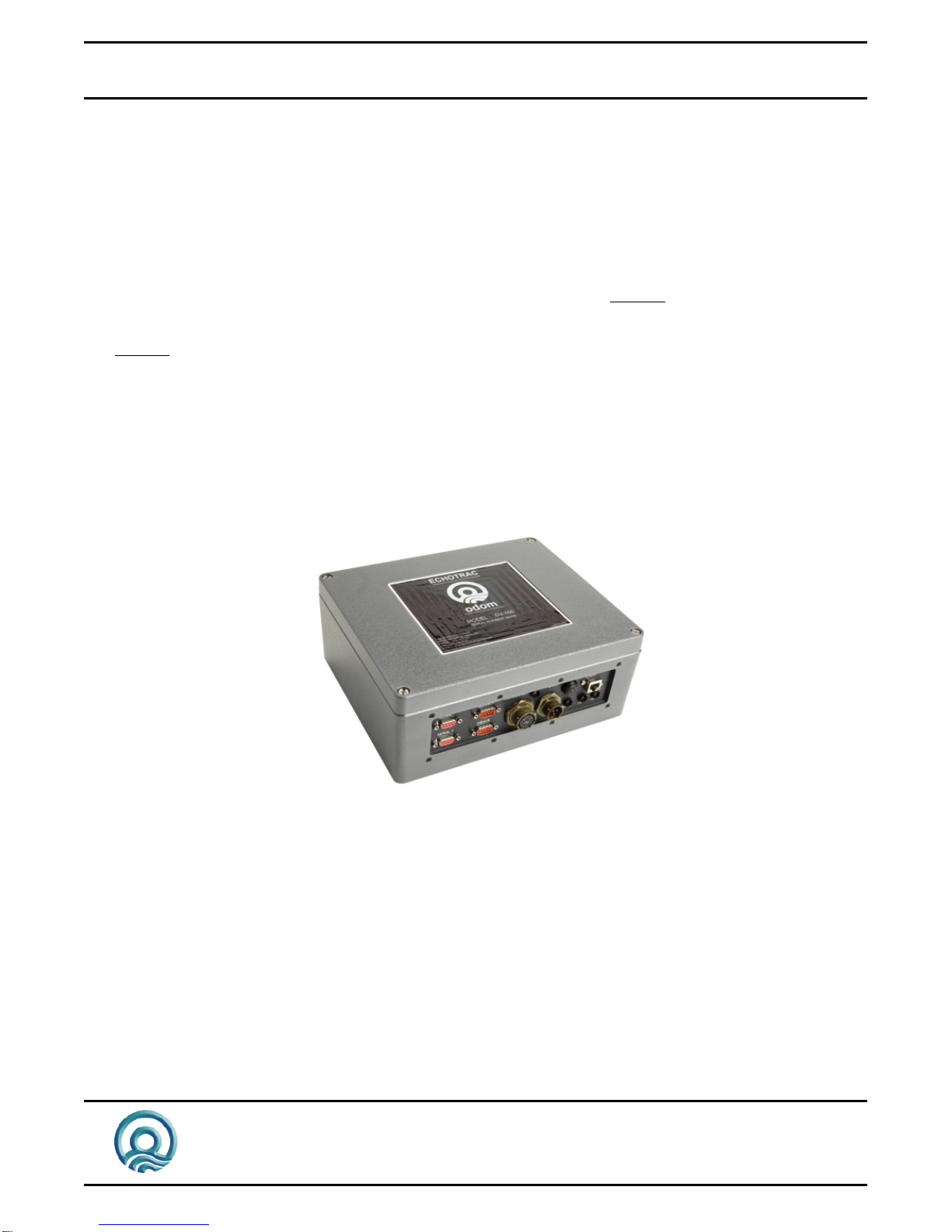
2.2 Overview ..................................................................................................................................................... 8
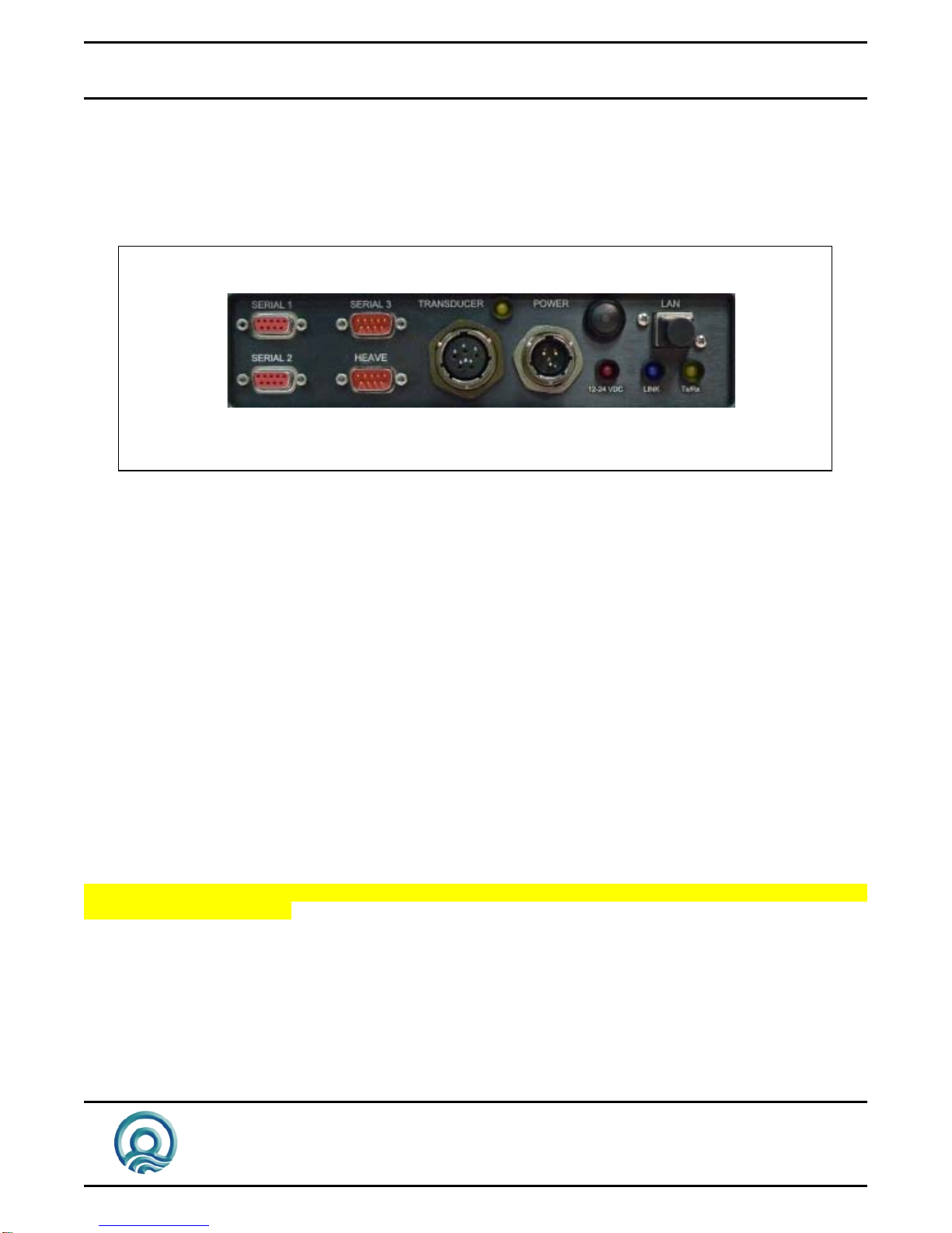
2.3 Cabling........................................................................................................................................................ 8
2.4 Power connector......................................................................................................................................... 8
2.5 Choice of operating frequencies ................................................................................................................. 9
2.6 Signal connector Transducer...................................................................................................................... 9
2.7 Serial Ports................................................................................................................................................ 10
2.8 LAN ........................................................................................................................................................... 10
2.9 Power button............................................................................................................................................. 10
2.9.1 Power-OFF ........................................................................................................................................ 10
2.9.2 Power-ON .......................................................................................................................................... 10
2.9.3 STANDBY.......................................................................................................................................... 10
2.10 Power indicator...................................................................................................................................... 10
2.11 Ethernet indicators................................................................................................................................. 11
2.12 Transmit indicators ................................................................................................................................ 11
3Installation...................................................................................................................................................... 12
3.1 Software installation.................................................................................................................................. 12
3.2 Setting up the equipment.......................................................................................................................... 12
3.3 Powering up the equipment ...................................................................................................................... 13
3.4 Transducer installation.............................................................................................................................. 14
3.4.1 “THROUGH HULL” transducer installation........................................................................................ 14
3.4.2 "SEA CHEST" transducer installation................................................................................................ 15
3.4.3 "OVER-THE-SIDE" transducer installation........................................................................................ 16
4Operational procedures................................................................................................................................ 17
4.1 Things to consider when calibrating.......................................................................................................... 17
4.2 How to calibrate the Echotrac CV............................................................................................................. 17
4.3 How to perform a bar check...................................................................................................................... 19
4.4 Shallow Water Operation.......................................................................................................................... 20
5Troubleshooting ............................................................................................................................................ 21
5.1 The Echotrac CV does not seem to be working........................................................................................ 21
5.2 The Echotrac CV power LED is off ........................................................................................................... 21
5.3 The Echotrac CV power LED is flickering................................................................................................. 21
5.4 What are the COM-port settings ............................................................................................................... 21
5.5 Known problems with Transducer............................................................................................................. 21
6Technical specifications............................................................................................................................... 23
6.1 Computer communications ....................................................................................................................... 23
6.2 Overview Serial Output string formats...................................................................................................... 24
6.3 Serial output strings .................................................................................................................................. 26
6.3.1 Echotrac SBT..................................................................................................................................... 26
6.3.2 Echotrac DBT..................................................................................................................................... 27

Echotrac CV100
User Manual
Page 4 of 4
Odom H
y
dro
g
raphic S
y
stems, Inc. Ma
y
28, 2008
6.3.3 Heave................................................................................................................................................. 29
6.3.4 DESO25............................................................................................................................................. 30
6.3.5 DESO DDV........................................................................................................................................ 30
6.3.6 DESO COMMANDS .......................................................................................................................... 31
6.3.7 NMEA DBS........................................................................................................................................ 31
6.4 Serial Data input / Chart annotation.......................................................................................................... 32
6.5 Serial heave input ..................................................................................................................................... 33
6.6 External Serial Control of Echotrac Parameters....................................................................................... 34
7Overview parameters and settings.............................................................................................................. 36
7.1 External Ethernet Control of Echotrac Parameters................................................................................... 36
8Uploading Firmware...................................................................................................................................... 37
8.1 Upgrading Motorola Processor Firmware................................................................................................. 37
8.2 Upgrading DSP Firmware......................................................................................................................... 38
9Echotrac CV Cable Connections.................................................................................................................. 39
9.1 Serial 1...................................................................................................................................................... 39
9.2 Serial 2...................................................................................................................................................... 39
9.3 Serial 3...................................................................................................................................................... 39
9.4 Heave........................................................................................................................................................ 39
9.5 LAN ........................................................................................................................................................... 39
9.6 Transducer................................................................................................................................................ 40
9.7 DC............................................................................................................................................................. 40
Appendix A. CABLE CONNECTIONS: ................................................................................................................. 41
Appendix B. Quick Start Operating Procedures ................................................................................................ 42

Echotrac CV100
User Manual
Page 5 of 5
Odom H
y
dro
g
raphic S
y
stems, Inc. Ma
y
28, 2008
1 INTRODUCTION
There are four Echotrac CV units named Echotrac CV100, Echotrac CV200, Echotrac CV300 and Echotrac CVM
(Mobile). This document covers the Echotrac CV100 and will refer to this unit as “Echotrac CV”. This Echotrac CV
supports one channel.
The Echotrac CV is a hydrographic echo sounder design incorporating the cutting-edge technology, features and
reliability of the Echotrac MKIII, plus the ease and flexibility of operation of a networked Windows®interface.
The Echotrac CV transceiver units are supplied in a compact stand-alone package that is ideally suited to many
shipboard installations. The Echotrac CV supports Chart-functionality in one optional format, a full size color LCD
“electronic chart”. The “electronic chart” is supplied in flexible modular enclosures complete with swivel mounting
hardware. A second option, that of operating the unit and collecting data on a networked PC, is also possible.
The optional color LCD module offers internal data storage (in .XTF format) and playback of the analog return
signal digitized to full 16-bit resolution. The Echotrac CV features a robust design and frequency agility enabling
the operator to precisely match the transceiver to almost any existing transducer. Operator selectable TVG
curves (10 Log, 20 Log, 30 Log, 40 Log, and Off) serve to optimise the Echotrac for shallow bottom detection
tasks and for Sonar imaging. The Echotrac CV features unsurpassed interfacing flexibility, offering 4 serial ports
that can be configured to interface with computers, positioning systems, motion reference units and remote
displays. The Echotrac CV also has an Ethernet port that outputs the 16 bit samples of the acoustic data for
further processing or visualization. The Echotrac CV also supports a number of output formats that are compatible
with most common Echo Sounder strings.
Figure 1: Echotrac CV100
To learn about the features of the Echotrac CV, this document is structured as a step by step manual; covering
the Echotrac CV as a product, how to install the software and the equipment, how to use all the different control
settings, how to perform certain procedures, how cables are wired to their connectors and troubleshooting.
Some of the major changes as of version 4.00 are:
- Replacement of the Echotrac Control Program with Odom eChart, a graphical data acquisition program.
Because the Echotrac Control Program 4.00 will become obsolete, it does not support some of the major
changes such as faster synchronization and adapting to the sounder’s hardware configuration.
- Faster synchronization due to improved communication protocol.
- Automatic detection of sounder(s) on the network and adapting to the sounder’s hardware configuration.

Echotrac CV100
User Manual
Page 6 of 6
Odom H
y
dro
g
raphic S
y
stems, Inc. Ma
y
28, 2008
1.1 Purpose
The purpose of this document is to explain the features and operation of the Echotrac CV.
1.2 Scope
The content of this document is focused on the end-user.
1.3 Glossary
DBS Depth Below Surface
DBT Dual Bottom Tracking
DGPS Differential Global Positioning System
DSP Digital Signal Processor
ETCV Echotrac CV
NMEA National Marine Electronics Association
SBT Single Bottom Tracking
TNC Threaded Nut Connector
TVG Time Varied Gain
VDC Volts Direct Current
1.4 References
[1] Title: Windows Flash Utility: OdomFlash.exe
Author(s): Patrick Oostenrijk
Report no: N/A
Version: 2.2
Date: 2007-02-27
[2] Title: Using Echotrac Ethernet Driver with Hypack
Author(s): Stephen Apsey
Report no: N/A
Version: 1.0
Date: 2006-07-17
[3] Title: Technical Specification Ethernet Interface
Author(s): Patrick Oostenrijk
Report no: N/A
Version: 1.8
Date: 2008-05-28

Echotrac CV100
User Manual
Page 7 of 7
Odom H
y
dro
g
raphic S
y
stems, Inc. Ma
y
28, 2008
2 PRODUCT DESCRIPTION
2.1 Specifications
Frequency
• High Band: 100 kHz-750 kHz
• Low Band: 24 kHz-50 kHz
Output Power
• Up to 200 watts RMS
Input Power
• 12 to 24 VDC 30 watts
Resolution
• 0.01m / 0.1 ft.
Accuracy
• 0.01m / 0.10 ft. +/- 0.1% of depth @
200 kHz
• 0.10m / 0.30 ft. +/- 0.1% of depth @
33 kHz
Depth Range
• 0.2 – 600m / 0.5 – 600 ft.
Chart Scales
• 5,10,20,40,80,100,200,400,800m
• 15,30,60,120,240,300,600,1200,
2400ft.
Phasing
• Automatic scale change, 10%,20%,
30% overlap or Manual
LCD Display
• 15 inch TFT Screen
• Sunlight Readable
• Internal Data Storage in XTF format
on 40GB Hard Disk
• Data Transfer via Ethernet interface
or USB Flash Drive
Sound Velocity
• 1370 – 1700 m/s
• Resolution 1 m/s
Transducer Draft Setting
• 0 – 15m (0 – 50 ft.)
Depth Display
• On control PC and LCD display
Clock
• Internal battery backed time,
elapsed time, and date clock
Annotation
• Internal – date, time, GPS position
• External – from RS232 port
Interfaces
• 4 x RS232 and 1 x RS422 serial
ports, baud rate selectable 4800-
19200.
• Inputs from external computer,
motion sensor, sound velocity.
• Outputs to external computer,
remote display
• Outputs with LCD chart – VGA
video out
• Ethernet interface
• Heave – TSS1 and sounder
sentence
Blanking
• 0 to full scale
Installation
• Desktop
Software
• Echotrac Control supplied
• ChartView supplied with LCD
configuration
Environmental Operating Conditions
• 0°– 50° C, 5 – 90% relative
humidity, Non-condensing
Dimensions
• 28cm (11”) x 23cm (9”) W x
11.5cm (4.5”) D
Weight
• 5 kg (11 lbs.)
Options
• Remote Display
• Side Scan Transducer – single or
dual channel side looking 200 kHz
for 340kHz for search and
reconnaissance

Echotrac CV100
User Manual
Page 8 of 8
Odom H
y
dro
g
raphic S
y
stems, Inc. Ma
y
28, 2008
2.2 Overview
On the backpanel of the Echotrac CV are all the connectors for serial communication interfacing, GPS data,
Ethernet communication, Transducer signals and power. See below, in Figure 2 for an overview of all the
connectors. Each item will be explained in more detail in the following chapters. The front panel has LED
indicators for Ethernet communication, Transceiver board operation and power.
Serial 1 Serial 3
Serial 2 Heave
LAN
Transducer
Power
Button
12-24
VDC LAN Status
LED
Power
LED
Transmit
LED
Figure 2: Overview of Echotrac CV
The Echotrac CV is a flexible unit designed for tabletop. Rack mounting can be accommodated with the included
special hardware. Where tabletop mounting is preferred, it is highly recommended that the unit be secured with
external 'tie-downs' for rough seas or heavy swells.
2.3 Cabling
All cabling is via the connectors located in the recessed panel at the rear of the unit. A view of the connector
arrangement is shown in Figure 2. Cable details are given in Appendix A. Care should be taken to route cables
using horizontal and vertical runs wherever possible. Avoid paths that run adjacent to transmitter feeder cables or
close to heat radiating elements such as steam pipes. For permanent installations, cables should be clamped at
regular intervals (1m) along their complete lengths.
2.4 Power connector
The Echotrac CV can be powered by DC power sources. DC operation requires an input voltage between 11 and
29 VDC (nominal 24 VDC). Average power consumption is approximately 25-30 watts. Frequently, power is
derived from two 12 V lead-acid batteries connected in series. These batteries (24V configuration), fully charged,
and in good condition, can normally power a unit for a full day without re-charging. Regulated DC supplies should
be able to source a short duration in-rush current spike of approximately 6 amps and an average current load of 3
amps. In the case of "charger" type (unregulated) supplies, the output should be "floated" across a battery load
and not connected solely to the echo sounder’s DC input. Details of the power cable are given in Appendix A.
Should the DC input voltage polarity be applied in reverse, an audible alarm within the unit will sound regardless
of the POWER switch setting. In the event that the input voltage drops below the minimum threshold the unit will
automatically shut down.

Echotrac CV100
User Manual
Page 9 of 9
Odom H
y
dro
g
raphic S
y
stems, Inc. Ma
y
28, 2008
Setting up two batteries in series (24 Volts DC system)
Battery 1
12 Volts Battery 2
12 Volts
(-) (-) (+)(+)
Jumper
DC Power cable
Using a jumper simply connect the positive post of battery 1 to the negative post on battery 2. Connect the
negative lead from the power cable to the negative post on battery 1 and the positive lead to the positive post on
battery 2. Always check the voltage with a voltage or multi-meter before connecting the DC power cable to any
equipment. Make sure that all the connecting equipment is also turned off before applying the power cables.
Otherwise the transients of such a ‘jump-start’ could damage the equipment.
2.5 Choice of operating frequencies
The Echotrac CV can be configured to use either a High or a Low frequency board, respectively 100 kHz – 750
kHz or 24 kHz – 50 kHz. Standard transducers are generally available from stock that support the frequency
ranges listed on the product description page (See 2.1 Specifications).
2.6 Signal connector Transducer
The signal from the transducer is passed to the Echotrac CV via a standard Odom transducer cable with a twist-
lock connector.

Echotrac CV100
User Manual
Page 10 of 10
Odom H
y
dro
g
raphic S
y
stems, Inc. Ma
y
28, 2008
2.7 Serial Ports
Serial 1
The Echotrac CV uses Serial port 1 to output depth data. Using a special Flash Utility program, the port is also
used to upgrade the software in the Echotrac CV. Another use of the port is to send commands to the Echotrac
CV or request certain parameter settings.
Serial 2
Serial port 2 is dedicated to connect the optional remote display to the Echotrac CV. The port can be configured
to use either an RS232 or RS422 protocol.
However, this feature is currently not supported with the Echotrac CV.
Serial 3
Serial port 3 is used to receive external GPS data in NMEA GLL or GGA format. It is best to only configure the
GPS to output only one of these strings as too much data can interfere with the communication processor’s other
tasks. When a GPS is connected to the Echotrac CV and is receiving position information, the Echotrac CV
100can output that GPS information on the Ethernet port.
Heave
Serial port 4 is used to receive motion sensor data in TSS1 format (heave). This port enables the Echotrac CV to
accept data from a motion compensator to apply corrections for the vertical movement caused by swells. The
Echotrac CV will only correct the depth for Heave. No corrections are done for Roll and Pitch.
2.8 LAN
The LAN port is used by the Echotrac CV to send and receive data on the network. The Echotrac CV can be
connected directly to a Hub or a Switch using a regular UTP CAT-5 ethernet cable. A regular cable is also known
as a ‘straight’ UTP cable. When the Echotrac is connected directly to a computer, a so-called ‘cross-over’ UTP
cable must be used. When a computer is directly connected to the Echotrac CV using a crossover cable, the
operating system on the computer may take 2-3 minutes before the computer has accepted a valid IP address. To
prevent this delay, you can assign the computer a static IP address or use a Hub/Switch.
2.9 Power button
The power switch in the ON position will power-up the internal circuitry. In the OFF position it will power-down the
internal circuitry.
2.9.1 Power-OFF
The main power switching circuitry is open in this position.
2.9.2 Power-ON
On "power-up", the unit performs a Self-test to check system memory and also tests the Non-volatile RAM battery
voltage. If there was a problem with the Non-volatile RAM, the factory defaults will be loaded. The unit then enters
the sounding mode and begins data acquisition.
2.9.3 STANDBY
The main power circuitry is energized, drawing current from the mains and providing regulated DC voltages to all
internal modules. The unit is no longer in the sounding mode when it is in the standby position. However, the
Parameter Entry System is enabled.
2.10 Power indicator
When the Echotrac CV is turned on, a red LED will be on to indicate that the internal systems have powered up
successfully. The red LED is located below the power button.

Echotrac CV100
User Manual
Page 11 of 11
Odom H
y
dro
g
raphic S
y
stems, Inc. Ma
y
28, 2008
2.11 Ethernet indicators
The TX indicator on the Echotrac CV indicates whether or not the data is transmitted on the Ethernet port. The
frequency at which the TX indicator flickers also indicates whether the Echotrac CV is outputting data at a slow or
fast pace.
The Link indicator on the Echotrac CV indicates that it recognizes the presence of a network. If the receiving end
of the ethernet cable is connected to a computer or a hub/switch that is not powered on, the link light will not be
on.
2.12 Transmit indicators
The Transmit indicators on the Echotrac CV indicate whether the Transducer is firing or not. The frequency at
which the Channel indicator flickers also indicates whether the Transducer is firing at a slow or fast pace.

Echotrac CV100
User Manual
Page 12 of 12
Odom H
y
dro
g
raphic S
y
stems, Inc. Ma
y
28, 2008
3 INSTALLATION
This section contains the information necessary to install the Echotrac Control Software, power-up and connect
the Echotrac CV. The installation procedure consists of a number of steps. Each step corresponds to a specific
chapter. It is recommended that these steps (chapter 3.1, 3.2 and 3.3) for the installation procedure be followed in
this order. See also the quick start procedure in Appendix B.
3.1 Software installation
Odom eChart, also referred to as the Echotrac Control program, is used to communicate with the Echotrac CV.
The manual for Odom eChart explains the installation procedure.
3.2 Setting up the equipment
The Echotrac CV is a lightweight unit designed for portability. An interconnection diagram is shown in Figure 3.
Care should be taken to route cables using horizontal and vertical runs wherever possible. Avoid paths that run
adjacent to transmitter feeder cables or close to heat radiating elements such as steam pipes. For permanent
installations, cables should be clamped at regular intervals (3 feet or 1 meter) along their complete lengths.
The Echotrac CV requires either an input voltage between: +11 and +29 VDC (standard). The unit consumes
less than 30 watts of power in normal operation. Power is frequently derived from one or two 12 V lead-acid
batteries. Two batteries (24V configuration), fully charged, and in good condition, can normally power a unit for a
full day without re-charging. Details of the power cable are given in the chapter 2.4 Power connector and the
Appendix .
All cables are attached to the connectors located in the recessed area at the left rear of the unit (See Figure 2 in
chapter 2.2). Connections are made through multi-pin “MS” style connectors, between the Echotrac CV, its power
source, the transducer and all computer or peripheral devices.
The following Interconnection block diagram shows everything that can be connected to the Echotrac CV. All
these peripherals are not required to use the basic functionality of the Echotrac CV.

Echotrac CV100
User Manual
Page 13 of 13
Odom H
y
dro
g
raphic S
y
stems, Inc. Ma
y
28, 2008
ECHOTRAC
CV100
Computer
Power Transducer
Optional External GPS (COM3) control (COM1)
Motion Sensor (Heave) Remote Display (COM2)
a/d
bc
gf
e
Figure 3: Interconnection block diagram
Before connecting any of the cables, make sure that the computer, the Echotrac CV and other peripherals are
turned off. The list below is a sequence of steps for connecting the Echotrac CV with the computer and GPS. If
any problems arise, see the Troubleshooting section.
a) Connect the RS232 cable between the computer and the DB9 connector labeled “Serial 1”, if you need to
collect depth data through the serial port or need to send command to the Echotrac CV.
b) Connect the cable from the Transducer to the connector on the Echotrac CV labeled “Transducer”.
c) Connect the power cable for the Echotrac CV to the connector labeled “POWER”.
d) Connect the UTP ethernet cable to the LAN connector if you want to collect data across a network.
If an external peripherals are used, then:
e) Connect the RS232 cable between the connector labeled “Serial 3” and the external GPS.
f) Connect the RS232 cable between the motion sensor and the connector labelled “Heave”.
g) Connect the RS232 cable between the remote display and the connector labelled “Serial 2”.
3.3 Powering up the equipment
The following sequence must be followed when powering up the equipment:
1. Turn on the personal computer.
2. Turn on the Echotrac CV. After turning the Power Switch from the OFF position to ON, confirm that the power
LED, Ethernet Link LED come on. After a few seconds, the Ethernet TX/RX LED and one or both of the
Transmit High / Low LEDs should start blinking.
3. Start the Echotrac CV Window Application program.
4. Turn on optional peripherals such as GPS or motion sensor.
5. Depending on water depth and bottom type, set the Tx Power to mid-range (position 6) in the Echotrac control
program.
6. Set the RxGAIN to about halfway on the maximum scale.
7. Adjust RxGAIN and TxPOWER to get a clear strong record with few alarms on the displayed depth.
Note: The Echotrac CV should always be turned on before running the Echotrac control program.
Note: Should you feel that a return to the sounder’s default parameter values is called for, then select the Default
Reset option in the Echotrac CV Window Application program.

Echotrac CV100
User Manual
Page 14 of 14
Odom H
y
dro
g
raphic S
y
stems, Inc. Ma
y
28, 2008
3.4 Transducer installation
Proper mounting of the transducer is a crucial part of the installation of any "survey" echo sounder. An improperly
mounted transducer will result in poor system operation and unacceptable data quality.
Important: See also chapter 5.5 Known problems with Transducer.
In the case of temporary installations, the transducer is often mounted over-the-side. In permanent installations
and "pay surveys," hull mounts are generally preferred and often required. In either case, the transducer should
be mounted as far below the waterline as possible. In cases where "over the side" mounts are exposed to wave
action, ensure that the transducer is mounted far enough below the surface so that it remains well submerged
during vessel roll motions.
A preferred mounting location is near the keel of the vessel, in an area where the planing attitude of the hull and
the pitch and roll angles of the vessel have the least effect at operating speed. The transducer should be
mounted far enough aft of the bow so that bubbles generated by the bow wave will not pass over the face of the
unit. Transducers should be located away from sources of turbulence and cavitation bubbles such as propellers,
bow thrusters and hull protrusions. Consideration should also be given to sources of mechanical noise generated
within the vessel (engines, propellers, pumps, generators, etc.). In some severe cases of mechanically coupled
noise, vibration-isolating mounts may be required to mechanically decouple the transducer from the hull.
Transducer mounting can be accomplished in many different ways. The following three chapters show common
configurations.
3.4.1 “THROUGH HULL” transducer installation
The top side of the transducer is accessible from inside the vessel while the transducer face is directly exposed to
the water. Care should be taken to protect the transducer from damage and turbulence by installing a fairing with
a sloping forward edge ahead of the unit. The fairing has the dual effect of both minimizing possible strike
damage and smoothing the flow of water over the face of the transducer.
Figure 4: Transducer mounted through the hull

Echotrac CV100
User Manual
Page 15 of 15
Odom H
y
dro
g
raphic S
y
stems, Inc. Ma
y
28, 2008
3.4.2 "SEA CHEST" transducer installation
In a "sea chest" mount, a fluid-filled enclosure large enough to contain the entire transducer is attached to the
outer hull of the vessel. The outer hull is removed within the area of the chest and replaced with an acoustically
clear "window" which is mounted flush with the hull surrounding the chest. Depending on construction, the
material selected for the acoustic window, and the draft of the vessel, access can often be gained to the
transducer from inside the hull without putting the vessel in dry-dock. In most installations, a water-filled
standpipe is incorporated into the "sea chest" design in order to provide hydrostatic pressure equalization.
Transducer cables generally leave these assemblies through stuffing tubes, which maintain the watertight integrity
of the chest.

Echotrac CV100
User Manual
Page 16 of 16
Odom H
y
dro
g
raphic S
y
stems, Inc. Ma
y
28, 2008
3.4.3 "OVER-THE-SIDE" transducer installation
A mount of this type is frequently constructed from a length of pipe. This fixture should be sized to position the
transducer well below the waterline and the pipe then fixed to a sturdy support on the vessel. Lines generally are
attached at the transducer pipe and tied off fore and aft in order to maintain a stable, horizontal transducer
attitude. Care should be taken to assure adequate protection for the transducer cable, particularly at the point
where the cable leaves the transducer body.
In all of the above installations, particular care should be taken to assure that the transducer radiating face
remains as parallel to the water surface as much as possible while the vessel is moving.

Echotrac CV100
User Manual
Page 17 of 17
Odom H
y
dro
g
raphic S
y
stems, Inc. Ma
y
28, 2008
4 OPERATIONAL PROCEDURES
The following sequences are typical operating procedures for the Echotrac. The procedures may vary according
to survey requirements and are intended only as a guide. It is assumed that the operator is familiar with the
various controls and their associated functions as detailed in the preceding sections of this manual.
4.1 Things to consider when calibrating
1. Calibrate daily in an area that is calm; avoid any “rocking” of the vessel.
2. Never use rope or material that might stretch on your calibration bar.
3. Perform calibration using the shallowest and deepest depths from your area.
4. If you do not have a velocimeter to compute the speed of sound, start with the default speed of the unit.
(5000 feet or 1500 meters per second or the speed from the previous day).The echo sounder is calibrated
using draft, index and speed of soundMeasure the draft using a survey tape measure
7. Apply index for the shallow calibration.
8. Apply speed of sound changes for the deeper depths.
9. If the water depth is less than 20 feet (6 meters). As long as your unit is in the average speed of sound
range, use only the measured draft and index for calibration. In other words, the speed of sound will have
little effect.
10. If the water depth ranges from .5 to 60 feet (18 meters), build a calibration bar that can reach the deepest
part of the survey.
11. For depths that exceed 60 feet use a bar that can reach as deep as possible. In areas such as these we
recommend that you use a velocimeter as a check.
12. Always document and save your work.
13. Selecting another tab in the Echotrac Control program exits the calibration functionality.
4.2 How to calibrate the Echotrac CV
The principle of echo sounding is based on measuring the time of arrival of an acoustic return (echo) referenced
to the time of transmission. The time required for sound to travel from a source (the transducer) to a destination
point (the seafloor or bottom) and back can be measured and multiplied by the velocity of sound in water. This
provides us with the distance that the pulse has traveled in the water column. Because the transmitted pulse
traveled from the transducer to the bottom and back again, the distance must be halved to obtain the true water
depth. Furthermore, other factors need to be included into the formula. If the transducer is submersed under
water, the distance from the water surface to the transducer, in other words the draft value, must also be
accounted for. If the calculated water depth does not exactly match the physically measured water depth, the
index value is used as a correction offset. The general depth formula is shown below.
d = v x t -k +dr ÍÎ d = ½ (a x t) – k + dr
2
Where:
d - Actual depth from water surface to the bottom.
v - Average velocity of sound in the water column.
t - Elapsed time measured from the transducer to the bottom and back to the transducer.
k - Index constant.
dr - Distance from the referenced water surface to the transducer (draft).

Echotrac CV100
User Manual
Page 18 of 18
Odom H
y
dro
g
raphic S
y
stems, Inc. Ma
y
28, 2008
Transducer d
r
d
a
d = ½ (a x t) – k + dr
Many users may not be familiar with the parameter “Index” or “k”, although it is likely that they have seen the
results of combining transducer draft and index constant into one draft figure. If you have noticed that the
measured draft, or the distance from the face of the transducer to the water’s surface is not the same as the draft
value entered into the sounder, then you have seen the result of lumping both together. This phenomenon is
most evident when using dual frequency transducers where both high and low elements are in the same housing.
Often, the draft values are very different for the two frequencies if no adjustable “k” parameter is incorporated.
The difference in “k” or electronic delay between a 200 kHz element and a 24 kHz array is substantial, and is the
reason behind the difference between the two “Calculated Drafts”.
Once the “k” value is determined, it will not change until either the sounder or the transducer is changed. The
Index parameter should be adjusted to make the measured draft and the calculated draft equal.
Since the accuracy of measuring the depth depends on the value used for the velocity of sound in water (along
with the other factors shown above), it is important that a realistic value for sound velocity is used. In water,
velocity is a function of temperature, salinity and pressure. Therefore, the sound velocity in one area may vary
from the sound velocity measured in another area. This means that whichever type of echo sounder is used, it
must be calibrated in order to provide the most accurate depth data at a given location.
The most common calibration technique is the “Bar-Check” method. This method, when employed properly, has
the advantage of determining the sound velocity, draft, and index value. When this method of calibration is used,
acoustic sound waves are bounced off a suspended target that is lowered to a known depth between the
transducer and the bottom. In this situation it is desirable that the digitizer will see only the Bar (the target) and is
unable to lock on to acoustic returns from the bottom. Because the Echotrac CV employs a dynamic tracking gate
or window through which the digitizer looks for returns or echoes from the bottom, manual control for the position
and width of the gate is necessary. This will force the digitizer to only detect returns from the Bar. See section 4.3
on how to perform a bar-check.

Echotrac CV100
User Manual
Page 19 of 19
Odom H
y
dro
g
raphic S
y
stems, Inc. Ma
y
28, 2008
4.3 How to perform a bar check
This section describes an example of how to perform a bar-check.
1. Setup the equipment and start the Echotrac control program.
2. Set the Range at 60 feet. Select the bar-depth (start with a shallow depth, typically 5 feet), bar-width (typically
1 foot), Sound velocity, Draft (measured), Index (start with 0), End-of-scale and Scale width. The Echotrac
control program is now in calibration mode because the bar-depth is greater than “0”.
3. Lower the bar into the water column and place it at 5 feet below the water’s surface. The Digitizer in the
Echotrac CV will expect to see a target at that 5.00-foot depth while rejecting all other returns (including those
from the bottom).
4. Adjust the index to the correct depth.
5. Change the bar depth in the Echotrac control program.
6. Adjust the sound velocity up or down until the digitized depth matches the measured bar depth.
7. Repeat steps 3, 4, 5 and 6 to verify the calibration procedure until your reading matches the depth of the bar.
IMPORTANT:
Adjust the draft only when the bar is at the shallowest depth, because this is where the sound velocity has little
affect on the calibration.
Adjust the sound velocity only when the bar is lowered to greater depths, because this is where the sound
velocity becomes pre-dominant.
Transducer
Bar gate width
Bar depth
Bar
Draft + Index
The figure above shows that the bar is placed under the transducer and kept at a certain measured depth using
cables.

Echotrac CV100
User Manual
Page 20 of 20
Odom H
y
dro
g
raphic S
y
stems, Inc. Ma
y
28, 2008
4.4 Shallow Water Operation
Set the Transmit power to mid-range, adjust the Receive gain to approximately midrange or Auto.
Ensure that the key parameters velocity, channel, draft, and index are correct. Amend any of these parameters as
required.
If necessary, slowly adjust the Receive gain controls until the desired quality is obtained and no digitizer alarms
are displayed. Adjustment of the Transmit power control may be called for at this point. A balance between
Receive gain and Transmit power is generally desired. In many situations AUTO power will satisfy record quality
requirements while at other times, where local bottom conditions dictate some variation of the Transmit
power/Receive gain ratio, a manual position may work best. Note that the MAX setting on any of the above
controls is seldom required.
Should the record show evidence of sporadic noise which cannot be overcome using the Receive gain controls,
and should the digitizer lose lock due to this noise, then several alternatives are available. First, determine
whether the digitizer is attempting to lock to a false echo or to the end of the Transmit Pulse. In either of these
cases, enter a value for Blanking which is deeper than the false return. This will force the digitizer to lock to the
bottom. If the Echotrac is connected to an external computer/data logger, confirm that correct digitized depths are
being transferred.
Other manuals for Echotrac CV100
1
Table of contents