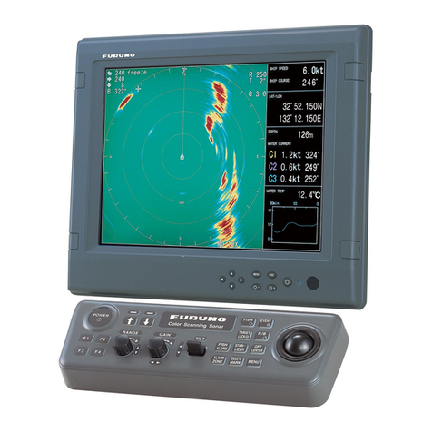
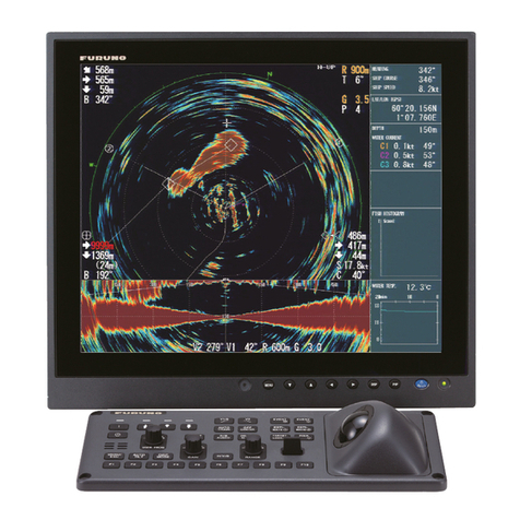
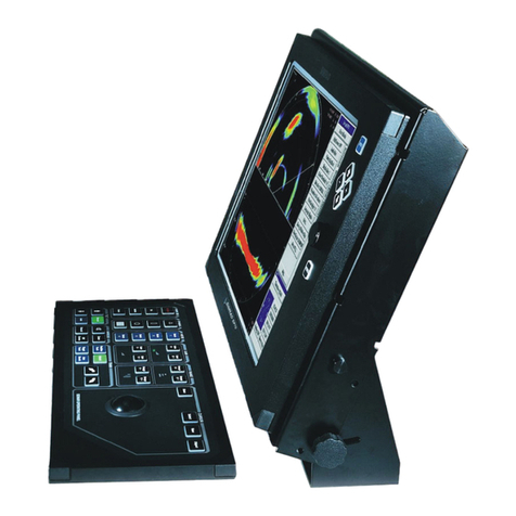
Furuno CSH-8L User manual

Installation Manual
COLOR SCANNING SONAR CSH-8L
SAFETY INSTRUCTIONS.................................................................................................................... i
SYSTEM CONFIGURATION .............................................................................................................. iii
EQUIPMENT LISTS ........................................................................................................................... iv
1. MOUNTING ................................................................................................................................1-1
1.1 Hull Unit ................................................................................................................................1-2
1.2 Transceiver Unit..................................................................................................................1-15
1.3 Processor Unit ....................................................................................................................1-16
1.4 Control Unit.........................................................................................................................1-16
1.5 Ground................................................................................................................................1-19
1.6 Transducer Cable Extension Kit CSH-1700 (Optional Junction Box)..................................1-20
1.7 Motion Sensor MS-100 (option) ..........................................................................................1-21
1.8 DC-AC Inverter (option) ......................................................................................................1-22
2. WIRING ......................................................................................................................................2-1
2.1 Cabling Outline .....................................................................................................................2-1
2.2 Hull Unit ................................................................................................................................2-3
2.3 Transceiver Unit....................................................................................................................2-5
2.4 Processor Unit ......................................................................................................................2-8
2.5 Synchronizing Transmission with Other Equipment............................................................2-15
2.6 Transducer Cable Extension Kit (option).............................................................................2-19
2.7 DC-AC Inverter (option) ......................................................................................................2-20
3. ADJUSTMENT............................................................................................................................3-1
3.1 Measuring TX Output............................................................................................................3-1
3.2 Heading Alignment................................................................................................................3-3
3.3 Setting for External Equipment .............................................................................................3-4
3.4 Smoothing the GPS Data......................................................................................................3-7
3.5 NMEA Version Setting...........................................................................................................3-8
3.6 Adjusting Echo Sounder Video .............................................................................................3-9
3.7 Sea Trial..............................................................................................................................3-10
APPENDIX
INSTALLATION OF CSH-8L ON RETRACTION TANK OF CH/FH SERIES SONAR,
OR 1800/3500 MM TANK ..............................................................................................................AP-1
PACKING LISTS.............................................................................................................................. A-1
OUTLINE DRAWINGS .................................................................................................................... D-1
INTERCONNECTION DIAGRAMS.................................................................................................. S-1
All brand and product names are trademarks, registered trademarks or service marks of their respective holders.
www.furuno.com

The paper used in this manual
is elemental chlorine free.
・FURUNO Authorized Distributor/Dealer
9-52 Ashihara-cho,
Nishinomiya, 662-8580, JAPAN
Telephone : +81-(0)798-65-2111
Fax : +81-(0)798-65-4200
A : JAN 2003
.
Printed in Japan
All rights reserved.
E : DEC . 16, 2011
Pub. No. IME-13200-E
*
00080940814
*
*
00080940814
*
(YOSH ) CSH-8L
*
00080940814
*
*
00080940814
*
* 0 0 0 8 0 9 4 0 8 1 4 *

i
WARNING
ELECTRICAL SHOCK HAZARD
Do not open the equipment
unless totally familiar with
electrical circuits and service
manual.
Only qualified personnel should
work inside the equipment.
WARNING
Install the specified transducer tank
in accordance with the installation
instructions. If a different tank is to be
installed the shipyard is solely respon-
sible for its installation, and it should
be installed so the hull will not be
damaged if the tank strikes an object.
The tank or hull may be damaged if the
tank strikes an object.
When assembling the hull unit, fasten
the shaft retainer and fastening band
with the torques shown below.
Shaft retainer: 20 to 25 N m
Jubilee clip: 6 to 8 N m
If torques are less than the above,
water leakage may occur because the
shaft may loosen and fall.
Turn off the power at the
switchboard before beginning
the installation.
Fire or electrical shock can result
if the power is left on.
SAFETY INSTRUCTIONS
The user and installer must read the appropriate safety instructions before attempting to install
or operate the equipment.
WARNING
Indicates a potentially hazardous situation which, if not avoided,
could result in death or serious injury.
CAUTION
Indicates a potentially hazardous situation which, if not avoided,
may result in minor or moderate injury.
Warning, Caution Mandatory Action
Prohibitive Action
DANGER
Indicates a hazardous situation which, if not avoided, will result in
death or serious injury.
Do not install the equipment where it
may get wet from rain or water splash.
Water in the equipment can result in fire,
electrical shock or equipment damage.
Be sure no water leaks in at the trans-
ducer installation site.
Water leakage can sink the vessel. Also
confirm that the transducer will not loosen
by ship's vibration. The installer of the
equipment is solely responsible for the
proper installation of the equipment.
FURUNO will assume no responsibility for
any damage associated with improper
installation.

ii
CAUTION
Turn off the POWER switch on the hull
unit before using the hand crank.
Bodily injury can result if the hand crank
rotates unexpectedly, because the raise/
lower motor may start up.
Observe the following compass safe
distances to prevent interference to a
magnetic compass:
Standard
compass Steering
compass
Processor
unit 0.4 m 0.3 m
Observing the following speed limits
when testing the equipment at sea trial:
Raising/lowering transducer: 16 kts max.
Transducer completely lowered: 18 kts max.
Exceeding above limits will damage the
equipment and void the warranty.
The zinc block near the transducer must
be replaced yeary.
The junction between the transducer and
main shaft may corrode, which can result
in loss of the transducer or water leakage
inside the ship. Replace the zinc block
yeary.
CAUTION
Attach protection
earth
securely
to the ship's body.
The protection earth is required
to the transceiver unit and DC-AC
inverter (option) to prevent
electrical shock.
Control
unit
Transceiver
unit
DC-AC
inverter
0.3 m 0.3 m
1.4 m 1.05 m
1.4 m 0.9 m

iii
SYSTEM CONFIGURATION
Hull Unit
CSH-8040
600 mm stroke,
CSH-8041
400 mm stroke
Transceiver Unit
CSH-8030-8L
Ship's Mains
100 VAC/
115 VAC/
200 VAC/
220 VAC/
240 VAC/
1 ,50-60Hz
DC/AC
Inverter
TR-2451
24/32VDC
Junction Box
Motion Sensor
MS-100
: Standard supply
: Option
: User supply
Processor Unit
CSH-5210
Control Unit
CSH-5211
Navaid
Current Indicator
AD Converter
Speed Log
E/S Interface
Remote Controller
Speaker
Display Unit (MU-150C, etc)
(2 max.)
CSH-1700

iv
EQUIPMENT LISTS
Standard Supply
Name Type Code No. Qty Remarks
Processor Unit CSH-5210 - 1 set
Control Unit CSH-5211 - 1 set
Transceiver Unit CSH-8030-8L - 1 set
CSH-8040 - 600 stroke
Hull Unit CSH-8041 - 1 set 400 stroke
CP10-05201 006-910-940 1 set For processor unitInstallation
Materials CP10-05501 006-911-000 1 set For transceiver unit
Installation
Materials Combinations of the cable are shown below.
Accessories FP10-02701 006-905-030 1 set For control unit
SP10-02901 006-907-700 1 set For processor unit
Spare Parts SP10-03001 006-910-950 1 set For transceiver unit
Installation materials (Cable combination)
Type Code No.
Transceiver/
Hull units Processor/
transceiver units Monitor/processor
units
CP10-05500 000-069-281 S10-6-15
CP10-05510 000-069-282 S10-6-30
CP10-05520 000-069-283 S10-15-5 S10-6-50
CP10-05530 000-069-284 S10-6-15
CP10-05540 000-069-285 S10-6-30
CP10-05550 000-069-286 S10-15-10 S10-6-50
3COX-2P-6C 5 m
CP10-05600 000-069-287 S10-6-15
CP10-05610 000-069-288 S10-6-30
CP10-05620 000-069-289 S10-15-5 S10-6-50
CP10-05630 000-069-290 S10-6-15
CP10-05640 000-069-291 S10-6-30
CP10-05650 000-069-339 S10-15-10 S10-6-50
3COX-2P-6C 10 m
Name Type Code No. Qty Remarks
S10-15-5 006-800-510 5 m
HULL cable S10-15-10 006-800-520 1 10 m Between transceiver and hull
units
S10-6-15 006-976-580 15 m
S10-6-30 006-976-590 30 m
Processor
cable S10-6-50 006-976-600 1 50 m
Between processor and
transceiver units
3COX-2P-6
C 5 m 000-146-500 5 m
Display cable COX-2P-6
C 10 m 000-146-501 1 10 m
Between display and processor
units

v
How to select transducer unit combinations
CSH – 8030 - 8L - (1) – (2)
(1): Input voltage 60 (100 VAC), 72 (220 VAC)
(2): Frequency 107 kHz, 85 kHz
How to select hull unit combination
CSH - (1) – (2) – (3) – (4)
(1): Stroke 8040 (600 mm), 8041 (400 mm)
(2): Frequency 107 kHz, 85 kHz
(3): Tank N; No tank, S; Steel, F; FRP
(4): Shaft length 13 (1300 mm), 15 (1500 mm), 23 (2350 mm), 40 (4065 mm), 94 (945 mm)
Optional Supply
Name Type Code No. Qty Remarks
DC-AC Inverter TR-2451 - 1 set
E/S Interface Unit VI-1100A - 1 set
Retractable Tank OP10-5 - 1 set Made of aluminum
Speaker SEN-21Q - 1 set
Transducer Cable
Extension Kit CSH-1700 000-068-207 1 set
Junction box, cable
assy
Motion Sensor MS-100 - 1 set
Remote Controller CSH-7040 - 1 set
Fairing 06-021-4502 001-159-790-10 1 set For an FRP ship

vi
This page intentionally left blank.

1-1
1. MOUNTING
NOTICE
Be sure the power supply matches equipment voltage
rating.
Improper power supply will damage the equipment.
Locate the transducer where the effects of noise and
air bubbles are minimal.
Noise and air bubbles will affect performance.
When selecting a mounting location keep the
following points in mind:
Keep equipment out of direct sunlight.
Keep equipment away from air conditioner.
Provide sufficient ventilation.
Select locaion where vibration is minimal.
Locate the equipment away from magnets or equipment generating
magnetic fields.
Keep the transducer cable away from oil.
Oil can corrode the transducer cable.
Do not expose the transducer to hot water.
Hot water can damage the transducer.
Do not turn on the equipment with the transducer
exposed to air.
Exposing the transducer to air may damage it.

1. MOUNTING
1-2
1.1 Hull Unit
1.1.1 Mounting location
Discussion and agreement are required with the dockyard and ship owner in deciding the
location for the hull unit. When deciding the location, take into account the following points:
• Select an area where propeller noise, cruising noise, bubbles and interference from
turbulence are minimal. Generally, the point at 1/3 to 1/2 of the ship’s length from the bow or
near the keel is the best. On-the-keel installation is advantageous for minimizing oil
consumption in comparison with off-the-keel. If the hull unit cannot be installed on the keel,
the center of the retraction tank should be within 1 meter of the keep to prevent a rolling
effect.
1/2 1/3 Within 1 m
Installation location for hull unit
• Select a place where interference from the transducers of other sounding equipment is
minimal. The hull unit should be at least 2.5 meters away from the transducers of other
sounding equipment.
• An obstacle in the fore direction not only causes a shadow zone but also aerated water,
resulting in poor sonar performance. Be sure to locate the transducer well away from any
obstacle in the fore direction.
• The space shown in the illustration below is required around the hull unit for wiring and
maintenance. If the transducer is to be operated in ambient temperature below 0°C, the sonar
compartment must be provided with a heater to keep the temperature above 0°C.
BOW
direction
400800
400 800
45˚
Hull unit maintenance space

1. MOUNTING
1-3
When the retraction tank is made locally, finish it so that
the welding bead does not protrude on the inner surface
of the tank. The tank guide will hit the bead, causing
motor born-out. The gap between the tank and tank guid
is 1 mm. Also when installing the tank, orient the welding
bead so it faces the port or starboard direction.
Welding bead
Welding bead
Tank guide
Bow
1.1.2 Installation of the retraction tank
The retraction tank is 1000 mm in length as supplied. Shorten the tank referring to the table
below so the transducer fully protrudes beyond the keel when it is lowered. Refer to the
installation procedure at the back of this manual for details.
Retraction tank installation
TANK CUTTING
Cut
In case of 1000 mm tank
750 mm (600 stroke,
shaft length: 1300 mm)
550 mm (400 stroke,
shaft length 945 mm)
Cut
Cut along hull bottom.
Note: It is not necessary to cut the main shaft when there is enough space above the hull unit.
In case of 1000 mm tank
750 mm (600 stroke,
shaft length: 1300 mm)
550 mm (400 stroke,
shaft length 945 mm)
How to shorten the retraction tank

1. MOUNTING
1-4
1.1.3 Assembly and installation of the hull unit
The hull unit is shipped disassembled as the parts shown on page 1-11 through 1-13.
Assemble the hull unit as follows:
Necessary tools
Tool Rating Remarks
Wrench M10 (Diagonal 17 mm)
Wrench M10 (Diagonal 30 mm)
Pipe Wrench Ø55 mm For tightening gland
Hex Wrench M6 (Diagonal 3 mm) For tightening transducer flange
1. Temporarily install the waterproofing attachment on the top of the main shaft and drill
holes for socket-set screws.
Shaft
Waterproofing
attachment
O-ring M6 Socket-set screw
(Use the wrench with diagonal 3 mm.)
30 mm Push in fully (O-ring will resist.)
Installation of waterproofing attachment
a) Mark drilling point on the shaft surface by tightening M6 socket-set screws (2 pcs.)
b) Remove the waterproofing attachment.
c) Drill holes less than 2 mm in depth. Use a drill with a Ø5, 120° tip. Do not drill holes
through the shaft. Use low rpm drill designed for stainless steel with cutting oil.
Less than 2 mm
5 mm Cut level.

1. MOUNTING
1-5
2. Fasten the raise/lower drive assembly to the main body flange with the trunnion shaft.
Main body flange
Split pin
Raise/lower
drive assy.
Trunnion shaft
Flat washer
Flat washer
Passing main shaft through the raise/lower drive assy.
3. Coat the top of the main shaft with a small amount of grease. Pass the main shaft
through the main body flange, and fix it temporarily with the shaft retainer. (The shaft
retainer should be secure enough to prevent shaft rotation.)
Grease threads.
Main shaft should
protrude by 44 mm from
top of shaft retainer.
Wipe off grease before
tightening
shaft retainer.
Raise/lower
drive assy.
Main shaft
M10
M10 Spring washer M10x40
44 mm
Passing main shaft through the raise/lower drive assy.
4. Tape the end of the transducer cable with vinyl tape to pass the cable through the main
shaft. Remove sheath of transducer cable by the length shown below with roller knife.
Note: Care should be taken not to damage inner wires when cutting the cable sheath,
only paper tape exists between the cable sheath and inner wires.
Use suitable roller
knife to cut sheath.
Main shaft length + 120 mm
L
Lower edge
of flange
Transducer cable

1. MOUNTING
1-6
5. After screwing the transducer into the main shaft, fasten two socket-screws (M6x10,
supplied).
Coat 50 mm of shaft
with grease.
Waterproofing
attachment
Hold here with pipe wrench.
50mm 140mm
Socket-set screw
M6x10, 2 pcs.
Rotate trans-
ducer to screw in
main shaft.
Note: Screw shaft 50 mm
into transducer flange.
Fastening main shaft to transducer
6. Clean the top of the shaft with alcohol, install the waterproofing attachment and apply
Lock-tight (supplied) to the socket screw.
Clean with alcohol
here.
30 mm
Shaft
Waterproofing
attachment
M6 socket-set screw
(Apply Lock-tight.)
Cleaning the shaft

1. MOUNTING
1-7
7. Inscribe bow mark on the top end of the main shaft and install the fastening band, O-ring,
waterproofing material, cable gasket, cable washer and fastening gland. Use two
socket-set screws (M6x8) to fasten the waterproofing material.
Inscribe mark in
line with bow mark
on transducer.
Fastening band
Tighten to torque of 6-8 N cm.
Cable gasket
Fastening gland
Cable washer
BOW mark
Fastening band Fastening gland
BOW mark
O-ring
Waterproofing material
130 mm
O-ring Waterproofing material
Cable gasket
Socket-set screw
Cable washer
Shaft
retainer
When assembling the hull unit, fasten
the fastening band with the torques of
6 to 8 N m.
If torque is less than the above, water
leakage may occur because the shaft may
loosen and fall.
WARNING
Installing fastening band and cable gland
Note: Tighten hex bolts to torque of 3.92 N·m to 4.90 N·m.
8. Install grease cotton on the main body as below.
a) Wind grease cotton onto main shaft.
b) Mark on the cotton as below.
c) Remove the cotton from the shaft, and then cut it at the position of the mark. Discard the
ends.
d) Wind cottons as shown below.
e) Push cottons into the main body flange.
f) Tighten the grease cotton retainer.
Wind grease cotton
onto main shaft and
cut as below.
Space joints of cotton at 120°and push
into main body flange.
Tighten grease
cotton retainer for
gap of 7 to 9 mm.
Flat washer
120°
Setting grease cotton

1. MOUNTING
1-8
9. Attach the tank guide.
Align with bow
mark on trans-
ducer.
Bow mark
M10x55
Tank guide
M10
spring
washer
*: Measure between the top
of the transducer flange and inner
edge of the tank guide.
107 kHz
85 kHz 312 mm
288 mm112 mm
88 mm
600 400
Travel type
TX
frequency
Mounting location for tank
*
Installing the tank guide
10.Attach zinc block to main shaft.
Ship's bow Tank guide
Zinc block
Shaft diameter
φ
55
Attach zinc block
as close as possi-
ble to tank guide.
Orient round end
to tank guide side.
The zinc block near the transducer
must be replaced yeary.
The junction between the transducer and
main shaft may corrode, which can result in
loss of the transducer or water leakage
inside the ship. Replace the zinc block
yeary.
CAUTION
Attaching zinc block

1. MOUNTING
1-9
11.Fasten the hull unit to the retraction tank.
Gasket
M20
M20 Spring washer
M20 Flat washer
M20
Flat washer
M20x80
45
Raise/lower drive assy
BOW
Orient the hull unit as shown.
This will reduce shock and
vibration, caused by ship's
pitching and rolling, at the
raise/lower drive assy.
Fastening the hull unit to the retraction tank
12.Fix anti-vibration stays to the retraction tank.
Anti-vibration stays should be fixed to directions of ship’s bow – stern and port – starboard.
Anti-vibration
stay
Fixing anti-vibration stays to retraction tank

1. MOUNTING
1-10
13.Orient the main shaft so that the bow mark faces ship’s bow and fix it securely with the
shaft retainer.
Loosen shaft retainer
and rotate main shaft
so the bow mark on
it faces ship's bow.
BOW mark
Ship's bow
WARNING
Tighten bolts fixing shaft retainer for
torque of 35 to 38 N m.
If torque is less than the above, water
leakage may occur because the shaft
may loosen and fall.
Orienting the main shaft

1. MOUNTING
1-11
Hull unit shipment lists

1. MOUNTING
1-12
Other manuals for CSH-8L
1
Table of contents
Other Furuno Sonar manuals

Furuno
Furuno FSV-35 User manual

Furuno
Furuno FE-1280 User manual

Furuno
Furuno FSV25 User manual

Furuno
Furuno CH-270 User manual

Furuno
Furuno CH-37BB User manual

Furuno
Furuno CSH-5L User manual

Furuno
Furuno CSH-23/24 User manual

Furuno
Furuno CH-34 User manual

Furuno
Furuno FCV-360 User manual

Furuno
Furuno DFF-3D User manual

Furuno
Furuno FSV-35 User manual

Furuno
Furuno FCV-1000 User manual

Furuno
Furuno CSH-53 User manual

Furuno
Furuno 3D Sonar Visualizer F3D-S User manual

Furuno
Furuno CSH-5L Manual

Furuno
Furuno CSH-7 User manual

Furuno
Furuno CSH5LMK2 User manual

Furuno
Furuno FCV-582 User manual

Furuno
Furuno CH-250 User manual

Furuno
Furuno Black Box Searchlight Sonar CH-250BB User manual