Officina Stellare UltraCRC User manual

RC, UltraCRC, RiDK, RiLa, RiFast, RH "Veloce"
Telescopes – All models
USER MANUAL
Rev 2.0 – March. 2016 – download the latest version of this manual from www.officinastellare.com

EVEN EFORE YOU TOUCH YOUR TELESCOPE, PLEASE
READ CAREFULLY
General notes, in this page.
CHAPTER 2 – "WHAT IS IN THE OX" and
CHAPTER 3 – "HOW TO HANDLE THE
TELESCOPE"
If you handle the telescope in a wrong way, you could damage it, and such
damage is NOT covered by the warranty.
General notes about all telescopes:
Never use your telescope to look at the Sun, or even
near the Sun. Severe eye damage or even permanent
blindness may result.
Always cover your telescope in daytime or keep the dome
closed).
Never leave the uncovered telescope unattended in daytime.
Do not use Officina Stellare telescopes even to project the image
of the Sun. Pointing the Sun may produce serious damage to the
telescope. Secondary mirror, secondary mirror support or internal
electronic parts may be damaged or even set on fire!) simply by
the STRONG heat produced by the primary mirror when pointed
to the Sun.
NEVER use Herschel prisms or eyepiece filter. NEVER!!! Any
Officina Stellare telescope is far too big for such devices.
2

If you want to observe the Sun, use a professional filter, placed
IN FRONT of the telescope. A 15 cm 6”) off-center Astrosolar
filter is a good and cheap solution.
If you search planets or bright stars in daytime, pay great
attention before to put your eye to the eyepiece, if the telescope
points near the Sun.
In daytime don't look into the telescope while it slews to target.
Truss structure telescopes may be "dangerous" during daytime
because the open structure allows the light to enter also laterally.
Always use the provided black elastic cover.
Officina Stellare is not responsible for any
damage related to improper use of the telescope.
INDEX
Chapter 1 – Introduction……………………..…………….. Page 4
Chapter 2 – What is in the box…………………………….. Page 7
Chapter 3 – How to handle your telescope……………… Page 8
Chapter 4 – Electronic controls…………..………………. Page 9
Chapter 5 – Collimation…………..………………………... Page 15
Chapter 6 – Collimation from scratch …………. Page 19
Chapter 7 – The RH "Veloce"………………………………. Page 33
Chapter 8 – Care and cleaning of your telescope……… Page 37
3

CHAPTER 1: INTRODUCTION
Congratulations for your new telescope! Any detail of your Officina Stellare telescope, from the
primary mirror to the smallest screw, has been designed, machined and assembled to achieve the
best possible results, under any condition, both for astronomical or non-astronomical uses.
We used the best materials, the best CNC machines, and decades of experience to deliver simply
a real state-of-the-art instrument, to satisfy both professionals and the most demanding amateur
astronomers. From the optical, mechanical and electronic point of view. Each Officina Stellare
telescope, and any piece of optics mirror or lens) is 100% designed and figured in Italy*, in our
optical shop in Occhiobello near Ferrara) and in our assembly plant in Sarcedo near Vicenza).
We appreciate your feedback. Should you have any comment about your Officina Stellare
instrument, please let us know. Send your suggestions or criticisms also appreciations are
welcome, of course) to support@officinastellare.com. We are proud to build great telescopes,
because we love astronomy. For our efforts toward perfection, only the sky is the limit.
HOW DOES IT WORK?
The figure above represents UltraCRC, RiDK, RiLa and RiFast telescopes. They all look very
similar, but:
UltraCRC telescopes are modified Ritchey–Chrétien, with a 2-lens corrector group near the
focal plane but the secondary mirror is hyperbolic, like in "traditional" RCs).
4

RiDK telescopes are optimized Dall-Kirkham, with a 2-lens corrector and a spherical
secondary mirror.
RiLa and RiFast telescopes, are based on different "tuning" of the Harmer-Wynne scheme.
Like in the RiDK the secondary mirror is not hyperbolic, and this allows a bit "relaxed"
tolerance on collimation. The lens corrector group has 3 elements.
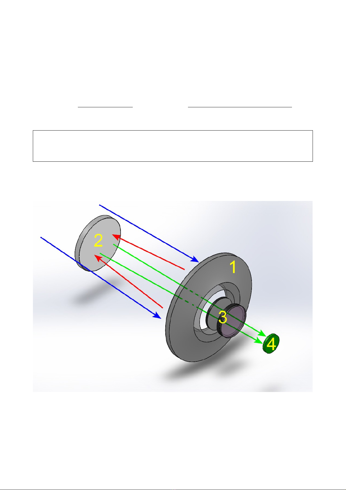
Anyway, in all such telescopes the light coming from the sky blue arrows) is focused by the
primary, concave mirror 1 & red arrows) on to a divergent secondary mirror 2). The secondary
mirror reflects again the light through a hole in the primary mirror, where a 2 or 3 lens corrector is
located green arrows and 3). The image forms at the focal plane 4) where a detector or an
eyepiece) is placed. The unique shape of mirrors and lenses, and a sophisticated system of light
baffles provide a focal plane that is reflections-free, well illuminated, wide and flat. All telescopes
provide, at the focal plane, a star spot size that is much smaller than almost any CCD/CMOS pixel.
Obviously the shape of mirror/lenses and their spacing is different in each model, to achieve the
best optical performance for a given aperture and focal ratio.
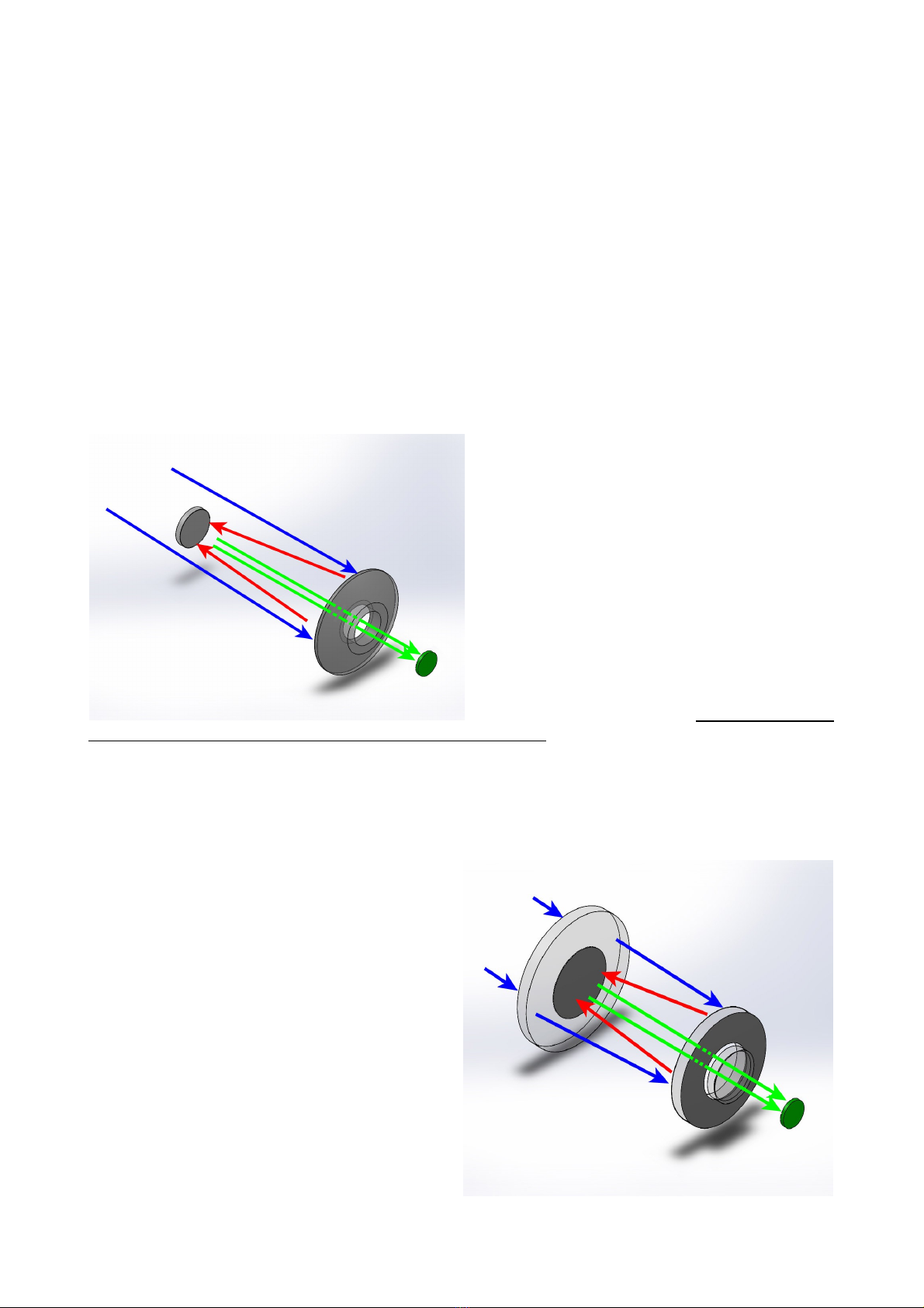
RC and RH "Veloce" telescopes are a bit different. In the RC series, a "pure" Ritchey–Chrétien
design, there is no lens group before the focal
plane and the secondary mirror is hyperbolic
figure at left). This is in theory the "best" and
simplest solution for deep sky imaging many
professional giant telescopes, including the
Hubble Space Telescope, are Ritchey–
Chrétien) but can't be done with low i.e. "fast")
f/ ratios. The size of the aberration-free focal
plane is smaller than in other schemes, and
collimation is really critical.
The RH "Veloce", on the other hand, is the
most complex optical scheme used by Officina
Stellare, but it is simply the best solution for
wide field photography, and it is the only really
new scheme for telescopes to enter production in decades! You see it in the figure below. In RH
telescopes, there is a meniscus front lens that is weakly convergent, and the primary mirror is a
"Mangin" mirror from the name of its French inventor). A Mangin mirror is a mirror that is coated
on the back surface, not on the front. The light passes through the glass, is reflected by the
coating and then passes again through the glass. For this reason, a Mangin mirror is called a
refractive-reflective optical element, and opens exciting possibilities to optical engineers. This
complex design includes also a corrector group
before the focal plane, achieving performances
impossible otherwise, with extraordinary "fast"
photographic performances over wide focal
planes. We called our RH telescopes "Veloce"
because this word, in Italian, means fast. A
curiosity about RH telescopes: since the
meniscus frontal lens) is convergent, the
Mangin mirror is smaller than the "nominal"
diameter of the scope, while the meniscus itself
is bigger than the nominal diameter, to ensure
a good illumination over the wide field of view
of such scopes. For example, the 200 mm
model has a 220 mm meniscus and a 190 mm
primary mirror. The secondary mirror is a
separated piece of glass, or it is made coating
the middle of the meniscus, depending on
model.
5

This wide range of different schemes allows Officina Stellare to satisfy very different customers,
for very different purposes, even non-astronomical, such as satellite tracking, laser
communication, defense applications, and more.
We can customize telescopes for diameter, focal length, size of the focal
plane, spectral response, and many other parameters, to fit any need, from
the amateur astronomer to the aerospace & defense industry, to the space
agencies.
That's why we offer so many different optical designs. We do not offer
compromises to our customer. We always offer the best solution. And if
we don't have your solution on the shelf, probably we can design and
build it!
And why do our telescopes have focal planes that are much bigger than
today's sensors? Because we want you to be happy about your instrument
even 10-20 years from now, when you will use your next CCD camera, and
the one after that...
* Only the frontal lens (meniscus of RH "Veloce" telescopes is made in Germany under Officina Stellare specifications.
6

CHAPTER 2: WHAT IS IN THE OX
Any Officina Stellare telescope comes, at the very minimum, with a set of Hex wrenches "Allen"
keys), documentation in electronic format on a USB key, and excluding RH "Veloce") the
electronic "box" and cables to control mirror heaters and tube fans; but many, many options are
available, such as shutters, collimation tools, adapters for your specific optical train, environmental
sensors, advanced electronics, and more. To help you check all the equipment, a checklist like
this is provided.
A two-page packing list for an Officina Stellare telescope. In this example, it is a RC-600 with
ATC-02C controller embedded on the scope), optional primary mirror shutter, optional hand
paddle, but no adapters or accessories. Please read carefully your packing list, double check it
against your order, and identify all the parts. Should you think something is missing, or you are not
able to identify any piece, please contact Officina Stellare immediately. We will be glad to help
you. Specific manuals may be provided for some specific accessories.
In big telescopes, the electronic
panel is embedded on a side of
the tube left photo) or in the
back of the primary mirror cell.
In smaller instruments, the
electronic may be a small,
external box. But the internal
circuit, the functionality and the
use are identical.
7

CHAPTER 3: HOW TO HANDLE THE TELESCOPE
Each Officina Stellare telescope has a very rigid and stiff structure, essential to maintain the
optical parts in the correct reciprocal position during regular use. But some part of the telescope
are quite delicate and precisely aligned. So pay great attention to "where you can grab" your
telescope to move it and to install it on your mount.
In the above photograph GREEN arrows indicate the "strong" parts of the telescope. The metallic
rings of the truss structure, dovetail plates and back handles. Any of this parts is ok to lift or handle
the scope use at least TWO of this parts). You can also use the carbon tubes of the truss
structure, if needed yellow arrows), if you use at the same
time also one "strong" part. Avoid to lift the scope using
the secondary mirror support, secondary mirror spider and
all light baffles red arrows). Those parts are quite delicate
and very precisely aligned. Even if your telescope is small,
we suggest to work with another person, to lift it on the
mount.
If your telescope is heavy– and you need a crane or some
other machinery to lift it – please use a strong rope and
pass it into holes of the middle and rear rings of the truss
structure, as you see in the photo at left. This procedure
will preserve alignment and the telescope finish.
8

CHAPTER 4: ELECTRONICS CONTROLS
Excluding RH telescopes, where there are only cooling fans, your Officina Stellare telescope is
always provided with one of the following electronics packages:
TC01 – The basic model.
ATC-02 – The advanced model, that allows also to control all functions of your telescope from
a remote PC.
Both require 12Vdc. The power consumption of the electronic itself and fans) is minimal, but
shutters and heaters may be a bit energy hungry, especially in big telescopes. Provide a 6A PSU
Power Supply Unit) for telescopes up to 400 mm, 10A for the bigger models.
TC01 – Telescope Control 01) –Controls only the primary and secondary mirror heaters and
cooling fans. You see it in the following photo.
On the left side you see the connectors for 12V dc
power and the on/off switch, if present. Units with no
on/off switch on/off switch are turned on and off simply
plugging in the power cable.
Some units have an internal fuse you must open the
box to change it), while some other have the fuse on the
power cable.
On the TC-01 you also see the connectors for the flat cables that power the primary and
secondary mirror heaters. Cables have different connectors, so it is not possible to make wrong
connections. The three knobs control the power to the heaters and the fans speed. As a general
rule, do not use the heaters, unless you see some mist on the mirrors. If you turn on the heaters,
try to keep them at the lowest temperature that avoid the mist. The intensity of the LED is
proportional to the power of each heater. Regarding the fans, run them at maximum until the
seeing stabilizes. After that point run them at half or one third power, or even turn them off until the
end of the night. The use of cooling fans is proportional to the temperature change that the
telescope suffers from day to night. The higher the temperature change, the longer you have to
run fans to reach equilibrium.
ATC-02 – Advanced Telescope Controller 02) –
The ATC02 is provided with a serial cable to
connect is to a Windows computer, physically
located in the vicinity of the telescope.
This PC, usually, will also manage a CCD camera,
the mount, the dome, autoguide, and so on, and in
case of a remote installation, it is remotely
controlled via a dedicated software, like Remote
Desktop, VNC or others.
On the ATC-02 you see the power connector,
on/off switch and mirrors heaters connectors, that are identical to those of the TC-01, and works
the same ways. The other connectors present are:
Environmental: to connect a humidity / temperature sensor, embedded in the telescope
body. Since those parameter are enough to compute the dew temperature, this sensor
allows the telescope to keep its mirrors just "warm enough" to avoid condensation
automatically, following the changes of the conditions during the night.
Hand: connector for the optional hand pad keyboard).
9

PC: serial connection to the PC cable provided). USB-to-serial converters works fine.
SH-1: connection to the optional) primary mirror shutters.
The ATC-02 also controls the optional electric motor that moves the secondary mirror along its
optical axis). The electrical connections for this motor, if installed, run on the same cable used by
the secondary mirror heater. Move the secondary mirror will change the BFL Back Focus Length,
i.e. the distance between the back plate of the telescope and the focal plane). This system is used
to focus the scope when a quick focus is essential, like is some non astronomical applications, or
when the equipment at the prime focus is too heavy for a traditional focuser, or you need some
extra BFL because of "thick" equipment at the focal plane, such as a filter wheel, a big CCD
camera, off-axis guider, and so on. The telescope "knows" the best position for the secondary
mirror – the design distance, where the optical performance are at best – and an internal sensor
permits the mirror to find this optimal position. But the movable secondary mirror is the only choice
in particular situations. You sacrifice a bit the optical performance simply to reach focus.
The ATC-02 has been designed with the computer control in mind, for a wholly remote-controlled
telescope. The hand pad is clearly a "second chance" solution. You can connect your ATC-02 to a
PC and to a hand pad at the same time. The ATC-02 will accept commands from both sources.
The latest command has priority.
4.1) Use of the ATC-02 with the computer
To control the ATC-02 from the computer, you will use our ATC-Remote software, provided with
your ATC-02. The software is quite simple, its interface is clearly divided in two. On the left you
have two tabs "Quick controls" and "Temperature control") where you can send commands to the
telescope. On the right other two tabs "General information" and "Data log") informs you about
the current and "historical" status of your scope. Let's look each tab in detail.
"Quick controls" tab
From this tab you can:
1) Choose the serial port where your telescope is connected,
and establish or terminate the connection. USB-to-serial
converters can be used. In this case check with Windows
the number of this "virtual" COM port.
2) Open/close the shutters, if installed
3) Enable the BFL control. The big "Find optimal position"
button brings the mirror to the "optimal" position, set during
manufacturing best optical performance).
4) Mirror movements. You can set an absolute position, or
move the mirror by ±1, ±0.25, ±0.05 or ±0.01 mm per step
5) You can enable a backlash compensation for the mirror
movements. Backlash compensate the minimum "dead time"
you see when you change the direction of motion in any
mechanical system, like your secondary mirror. Use this
parameter only if directed by Officina Stellare support.
Usually you simply look at the image captured by the scope
to change secondary mirror position, but for particular
situations a backslash control is useful.
6) With this buttons you can turn on/off the hand pad, if
installed. This is to avoid the local control of the telescope if
you are using it remotely) or simply to reduce the illumination
inside the dome.
10

"Temperature control" tab
From this tab you can:
1) Leave the temperature control OFF, or keep the mirrors at a
constant temperature only ABOVE ambient, of course).
2) Keep the mirrors a given temperature above the dew point
temperature calculated by the internal sensor).
3) Set the Pulse Width Modulation of each heater. PWM is
something like a limit to the "maximum power available". If
you heat the mirror too quickly, the mirror may warp a bit,
temporarily!) and produce bad images. To warm the mirror
slowly, set the PWM to no more than 50%. The software will
warn you if are using a "high power" set.
4) Set the fans speed. Run them at maximum until the seeing
stabilizes. After that point run them at half or one third
power, or even turn them off until the end of the night. The
use of cooling fans is proportional to the temperature change
that the telescope suffers from day to night. The higher the
temperature change, the longer you have to run fans to
reach equilibrium.
"General information" tab
From this tab you read:
1) Owner data, as written in the memory of the scope when it was produced.
2) Environmental data temperature, pressure, relative humidity and dew point), measured or
calculated) by the telescope sensors.
3) Tilt and roll of the scope, as read by gravity-referred sensors internal to the scope. This data is
useful to control if the telescope has reached the "park" position or is moving at all. In other
word, this is a way to control if the telescope mount is working properly. This sensors are not
sensitive enough to point the telescope, but will be useful during the setup and use of a remote
controlled telescope. By the way, we suggest to install webcam, possibly with IR capabilities, in
the dome, to take a look to your telescope during operation!
11

4) Back focus position. This data is meaningful only if the secondary mirror motor is installed. The
minimum, optimal and maximum position are real measurements, in mm.
5) Real temperature, set temperature and heater status for the primary mirror
6) As above, for the secondary mirror
7) Fan speed. Parameter 5, 6 and 7 are set in the "Temperature control" tab.
"Data Log" tab
Simply shows as two multiple Y-scale graphs a log of all the above parameters. On the bottom you
read the COM port, telescope model, software version, telescope firmware version.
4.2) Use of the ATC-02 with the hand pad
The hand pad is connected to the ATC-02 via a male-male RJ-45 cable. The cable fits also the
"PC" port on the ATC-02, but there is no risk of damage if you make a mistake. If you plug the
hand pad cable in the "PC" connector or vice-versa, the hand pad or the PC connection) will
simply not work. Use the correct connector!
As soon as you power up the ATC-02, the hand pad will briefly show the firmware revision. This
information will be useful if you contact Officina Stellare customer service. After the firmware
revision, you will see briefly the serial number, telescope model and owner information, written in
the memory of the scope following your order. Finally, the hand pad will start to "cycle" between
five different screens.
The first three lines of the display will continue to cycle between the five "screens". The user will
interact only with the last line.
12

This table summarizes what you read in the five "screens". Look at the hand pad for a while to
familiarize yourself with this five "screens"
You read… Notes
First screen
1st row: Date and time Format is dd/mm/yy, 24h. Available only if a computer is
connected, and read from the computer. There is no clock or
battery inside then ATC-02.
2nd row Shutter status and
fans speed
If shutters are not installed, their status is always "OPEN". Fan
speed is given as percent of maximum.
3rd row: BFL position and
last command
The BFL Back Focus Length) is the distance between the focal
plane and the back plate of the scope. "Local" or "Remote"
indicate if the last command to the position of the secondary
mirror has been given locally via hand pad) or from the PC. This
information is meaningful only if the optional secondary mirror
motor is installed.
Second screen
1st row: "Mirrors
temperatures"
Just a reminder of what you read in this screen – obviously the
temperature of the two mirrors.
2nd row P xx.x OFF S xx.x
ON
Primary and secondary mirror temperatures, in Celsius degrees,
and if each heater is ON or OFF at the moment.
3rd row: Set x.x Set x.x Set temperature for the two mirrors
Third screen
1st row: Hum xx.x, Temp
x.x °C
Humidity in % and local temperature
2nd row Pressure xxxx mB Local pressure, in mbar
3rd row: Dew point xxx °C Local dew point, in °C. Dew point is calculated from temperature
and relative humidity.
Fourth screen
1st row: "Auto Heating" Just a reminder of what you read in this screen – the status of the
mirror heaters.
2nd row Prim…
OverDwP…
If the primary mirror heater is ON or OFF, and the required
temperature over dew point usually a good choice is 2°C above
dew point).
3rd row: Sec… OverDwP… Same as above, for the secondary mirror.
Fifth screen
1st row: Backlash: … Backlash: see point 5) of the "Quick controls" tab, above, for a
description of this function.
2nd row Direction: …. Direction of backlash inward or outward)
3rd row: Value… Backslash value, in units of 1/100 mm
To give commands to the telescope via the hand pad, you
will use the four buttons, marked [E] Enter), [S] Step), [+]
and [-].
[+] and [–] change the current menu item or value once
you entered one specific function).
[E] enters each function from the menu and goes back to
the menu after you set the value.
13

[S] is used only to change the Step of the secondary mirror movement, to change the BFL.
The menus available use [+] and [–] to see them in the last line of the display) are described here:
press [E] to enter each function
SET TEMPERATURE
Use [+] and [–] to change the values, [E] goes back
SET FAN SPEED
Use [+] and [–] to change the values, [E] goes back
BFL CONTROL. This is the only menu item that has sub-menus. Again, use [+] and [-] to choose,
[E] t enter each function
MOVE SECONDARY MIRROR
Use [+] and [–] to move the mirror, [S] to change step, [E] goes back
FIND OPTIMAL
Pressing [E], the mirror will reach the optimal position, set during manufacturing.
BACKSLASH ENABLE
Press [+] to enable the backslash compensation, [-] to disable, [E] goes back
BACKSLASH VALUE
Use [+] and [-] to change the backslash value unit is 1/100 mm). [E] goes back
BACKSLASH DIRECTION
Use [+] and [-] to set the direction of the backslash movement. [E] goes back
EXIT AND GO BACK
With [E] you go back to the top level menu.
DISPLAY BACKLIGHT
Use [+] and [-] to change display brightness, [E] goes back
SHUTTER
Use [+] and [-] to open or close the shutter, [E] goes back
14

CHAPTER 5: COLLIMATION
The purpose of collimation is to bring the optical axes of all optical elements to coincide – and
bring them as close as possible to the mechanical axis.
Collimation is important for any optical system, but it is really essential for a telescope. The best
telescope of the world will produce horrible and useless images if it is not collimated.
As a general rule, the faster i.e. with a low f/ratio) the telescope, more critical is the collimation.
This procedure is similar, but not identical, to the procedure for the “Veloce” series of
astrographs . For the “Veloce” collimation please read also Chapter 7.
Every telescope is shipped from our plant perfectly collimated. We use several dedicated tools and
some time to achieve this. But vibrations or little shocks during transport may move a bit some
parts. A movement of any optical element of less than a quarter of a millimeter less than 1/100 if
an inch) will require the scope to be collimated. Sorry, nobody's fault – it's the laws of optics. The
good news is that since every Officina Stellare telescope has a very good mechanics, once you
have a good collimation, the telescope will stay collimated for a long time.
5.1) Some notes about collimation
The first, obvious, step in collimation is to check if your telescope needs collimation at all. All you
need is a bright star, high in the sky 45° or more above horizon) and some eyepieces, or a
camera that shows images quickly we suggest at least one image per second; a webcam or a
DLSR with LiveView is a perfect choice). Leave your telescope reach the ambient temperature
before to proceed with collimation, say 90 minutes after sunset. The cooling fans will help a lot.
You can also use an artificial star, available by astronomical equipment retailers, but a real star is
much better. Start looking at the star with the lowest power i.e. longest focal length) eyepiece you
have. DO NOT USE 90° PRISMS.
If the secondary mirror has an electric motor to change the
BFL Back Focus Length), turn “ON” the scope electronic
control and set it to the “factory zero”. The command is
"FIND OPTIMAL BFL". Turn off the scope when done. This
will set the mirror spacing for best performance, as
established by the optical design.
Point the star, bring it in the very center of the field of view
and bring it out-of focus. It is not important if you go in-focus
or out-focus. You should see something like the image at left:
The white disk is the out-of focus image of the star.
The "shadow" of the secondary mirror and its supports are
clearly visible green arrows). Here also a cable protruding
from the secondary mirror assembly is visible the “bump” in the direction of the red arrow).
All the white area red arrow) will change continuously, because of the turbulence in the
Earth's atmosphere in astronomy the stability of the atmosphere is called the "seeing").
A grain of dust somewhere on the optic may show a circular pattern yellow arrow). Just ignore
it, this has no effect on collimation, and has no effect on telescope's performance.
15

If the seeing is really terrible – i.e. there is a
strong turbulence in the atmosphere – the
out-of-focus star may change "wildly", and
change in a fraction of a second in size,
color, shape image at right). If this is the
case, the seeing is simply too bad to
continue. You have to wait another night or
use an artificial star). If this happens when
you have just open your "warm" dome in a
very cold night, just wait one hour to check if the problem is due to local turbulence the telescope
is much warmer than the air). It is a good practice to open the dome and start telescope's fans)
as soon as the sun sets. By astronomical twilight, the telescope will be very close to thermal
equilibrium with the environment, minimizing the thermal local) turbulence.
5.2) How to check collimation
1. Be sure your telescope is in thermal equilibrium with the environment.
2. Start with the lowest power longest focal length) eyepiece available. DO NOT use a 90° prism.
3. Choose a bright star at least 45° above horizon. Bring the star in the center of the field of view
and look at the defocused image. You MUST use a star, a planet cannot be used since it is not
a point-like source of light.
4. If the dark shadow is clearly NOT in the center of the white disk jump to section 5.3,
“Collimation procedure”.
5. If the dark shadow of the secondary mirror looks in the middle of the white circle, change a bit
the focus, using the telescope focuser, NOT the electric motor of the secondary mirror, if
present. The white disk will became smaller or bigger. Check if the shadow is always in the
middle the human eye is a very good "device" to control if two circles are concentric). Always
keep the image in the center of the field of view using the telescope mount. Focus from a "very
big" to a "very small" image, and continue to check if the shadow is always in the middle of the
white spot. Find the size of the spot that is more comfortable for your eye to detect
concentricity. If you are using a camera you may have to change exposure time; you may also
measure the single images using specific software or a simple ruler, working directly on the
computer screen). If you are using a camera set the exposure time so you can see different
shades of gray in the star image.
6. If the image is too bright or too dim to see clearly the shadow of the secondary mirror, choose
a different dimmer or brighter) star, or change exposure time.
7. If the shadow always look concentric, change eyepiece with a more powerful one shorter focal
length) or zoom the electronic image, and repeat steps 3-5. For this step a visual magnification
of around 200-300x is a good choice.
8. If the shadows always look concentric, the collimation of your scope is "good enough" for any
reasonable application. Jump to sections 6.5 and 6.6, for “fine tuning”.
The image at left gives you an idea about what
you will see during this procedure while you
change focus.
Remember, always keep the star in the center of
your field of view, using the telescope mount.
5.3) Collimation procedure
If the shadow is not in the middle of the white disk, start collimation from the primary mirror, for the
very simple reason that 90% of the times you can reach a good collimation working only on the
primary mirror, and you need no particular tool to do so.
16

First of all, you must learn how to move tip-tilt) the primary mirror. Take a look to the images in
this page and familiarize yourself with the tip-tilt screws of your primary mirror.
In “big” scopes i.e. 50 cm and above) you must follow this procedure to operate on the three big screws that control the tip-tilt
movements of the primary mirror. This screws are rotated using a metal bar or a big screwdriver 1, left image). But before you can
operate them, you have to remove the black cap 2, left image) and remove the external locking “bolt” 3, left image). The tool to do
so has been provided with the scope. Once you have removed the external locking bolt, you will see the internal locking bolt 2, center
image). Use a small hex wrench to move it a bit inside the scope 1, center image). Just rotate it 4-5 turns. The bolt must move away
from the back plate, i.e. go inside the telescope. The big tip-tilt screw can now be operated using a metal bar or a big screwdriver
right image). Please note that even in big scopes each screw turn will move the mirror just one millimeter. Collimation screws are
spring loaded using cup springs in big scopes) so there is no need, when you tight one screw, to loose the other two or vice versa.
When you have set the tip-tilt position of the primary mirror, bring the internal locking bolt again in contact with the back
plate of the scope and put back in position the external locking bolt and the black cap. There is no need to apply too much force on
the internal locking bolt. Just rotate it until it stops against the back plate of the telescope. It is the external bolt that does the real job.
In smaller telescopes there are three big screws to set the tip-tilt position of the primary
mirror number 2 in the photo at left). If your telescope has also the safety set screws 1)
loose them 4-5 turns before to operate on the big screws using the specific tool 3),
included with the scope. When you finish, tight the safety set screws. Do not apply too
much force. Just let them touch “gently” the internal mirror cell.
Please note that in all Officina Stellare telescopes each collimation screw turn will move
the mirror just one millimeter. Collimation screws are spring loaded, so there is no need,
when you tight one screw, to loose the other two or vice versa.
Now go back to our defocused star, where the shadow is not in the middle of the white circle and...
go to the next page!
17

1. The gray circle is your field of view through the eyepiece. The white circle is the defocused star
and the black spot is the position of the secondary mirror's shadow. A collimated scope will
look like "A", above, at any magnification.
2. If the shadow si not in the middle in our example, "B", is at the "8 o'clock" position) then move
the telescope, using the mount motors, so the image goes in the same direction, so the
defocused star goes near the edge of the field of view at the "8 o'clock" position, like in "C".
3. Try to tight or loose a bit one of the collimation screws. Discover which screw or screws) move
the star image in the direction of the center of the field of view like the black arrow in "C").
When the image will go back to the middle of the field of view, it will be more centered.
4. Repeat step 2-3 until you reach collimation image "A", above).
5. Use a higher magnification and repeat.
Some notes about this operation:
It is very unlikely you have to move any collimation screw more than one turn – probably you
will reach collimation with less than half a turn.
Have someone to help you while you look at the eyepiece – or use a camera so you can see
the image while you work on the screws. It is a good idea to label the three collimation "A", "B",
and "C", and memorize the direction of the movement given by each screw. Obviously the star
will move in the opposite direction along a line when you turn screw "A" clockwise or
counterclockwise. Movements due to screws "B" and "C" will be 120° apart.
It is a good idea to mark the initial positions of collimation screws with a felt tip pen and keep
track of what you do like “screw A 45° CW – screw B CCW 30°...” and so on). Doing so, you
will always be able to “undo” a wrong action, and, if needed, to go back to the original position.
In all Officina Stellare telescopes the collimation screws are spring-loaded, so if you tight one
screw there is no need to loose the other two.
And, very important: KEEP YOUR TIME, AND START WITH SMALL MOVEMENTS 1/8 or
1/16 of a turn).
When you have a perfectly symmetrical figure at any magnification i.e. when the dark shadow is
always in the middle of the de-focused star) you are done, and you can use your scope for any
reasonable purpose. Go to section 6.5 and 6.6 for fine collimation and focuser tip-tilt.
5.4) And if I'm not able to reach collimation?
It is quite unlikely, but it is possible that your secondary mirror moved a bit during transport. If this
is the case, you will not be able reach a good collimation using only the primary mirror tip-tilt
control. You have to refer to Chapter 6, Collimation “from scratch”.
18

CHAPTER 6: COLLIMATION “FROM SCRATCH”
The following procedure should be used only if you are not able to reach an
acceptable collimation using the procedure described in Chapter 5. We suggest to
contact our customer care (support@officinastellare.com) before to try the
following procedure; just to check with our technicians that the telescope really
needs collimation, or that the problem is not elsewhere in the optical train. This
procedure DOES NOT APPLY to the RH “Veloce” family of astrographs.
This figure helps you understand the text:
•Red arrows: mechanical centering of the
secondary mirror.
•Blue arrows: longitudinal movements of
primary and secondary mirror
•Green arrows: tip-tilt regulation of
primary and secondary mirror
•The lens corrector group, if present, is
fixed and cannot be adjusted by the final
user see text).
•The green disk is the focal plane.
During this “collimation from scratch” procedure you will work on all the degrees of freedom visible
in the above figure. The final user cannot work on the lens corrector group, but since those
elements are "glued" in position and they have very strong metal cells and spacers, it is in practice
impossible they move or get loose. In other words, you will set the mirrors longitudinal position
blue arrows) and orientation green arrows) relative to the fixed lens group, if present or
relative to the back plate, in RCs. Also the concentricity of the lens group and/or back plate) with
the primary mirror is guaranteed by the sturdy primary mirror cell and back plate structure, and
cannot be changed. It is fixed by construction.
VERY IMPORTANT! There is not an “unique” solution for collimation. There are “families” of
positions for the optical elements) that do provide an image quality within the telescope
specifications. In other words, if the secondary mirror is a bit off from its “perfect” position, the
collimation process will bring also the primary mirror a bit “off”, but in a way that compensate for
the secondary mirror “error” within thigh limits, of course). For this reason it is absolutely normal
that, after collimation, the optical axis of the telescope does not coincide with the mechanical axis
of the tube, even if the telescope does perform perfectly form the optical point of view and the
mount is “perfect”. This difference, if measurable, is usually really small a few arcmins maximum)
and can be compensated by the pointing system of the mount creating a “mount model”.
The Takahashi collimation tool (or at least a collimation eyepiece) is required for this
procedure. An holographic laser (included in the Officina Stellare deluxe collimation kit)
may be useful if your mirrors are “wildly” out of position (typically if you have
disassembled you telescope, like for mirror re-coating).
You will need also a Vernier caliper. If it is digital usually 0.01 mm resolution) it is better, but
also the traditional mechanical version usually with a resolution of 0.05 mm) is ok.
If you will use the laser, you will also need to point the scope perpendicular to a wall, to project
on the wall the laser pattern. If a wall is not "available", a big piece of cardboard or a wood plate
19

will do the job. What is important is that this flat surface can be set perpendicular to the optical
axis, with a reasonable tolerance. Just check with a meter tape that different points of the frontal
ring of the telescope have the same distance from the flat surface, within a centimeter or so.
This is enough.
Collimation from scratch or CFS, for short) is a 5 steps procedure:
1. Mechanical centering of the secondary mirror Section 6.1).
2. Check the distance between mirrors Section 6.2)
3. Secondary mirror tip-tilt regulation Section 6.3).
4. Primary mirror tip-tilt regulation Section 6.4 and 6.5)
5. Focuser or camera) tip-tilt, if needed Section 6.6).
Steps 1 and 2 are usually only just quick checks. It is very unlikely you will need to do any change
during those steps. Also step 5 usually requires no action from the user it is more probable you
need to do something in RiFAST and RiLA telescopes, because of the lower f/ratio). The “core” of
the collimation process is only steps 3 & 4.
Steps 1 and 3 can be performed indoor. All other steps requires at least an artificial star, or much
better!) a real star during night. The whole process will require two to three hours. The good news
is that after this procedure you will not touch the telescope collimation again for a long time – even
years, if you do not transport the telescope frequently. After a “normal” shipment, usually you have
to perform only step 4, as described in Chapter 5.
We strongly suggest to have someone who can help you, at least for step 3, otherwise you will
have to move many times from the back of the telescope to the front, where the collimation screws
of the secondary mirror are located.
Let's see each step in detail.
6.1) Mechanical centering of the secondary mirror.
This step is usually just a check. Each telescope is accurately set during manufacturing! Using the
vernier caliper, check the secondary mirror support is mechanically centered in the front ring of the
telescope; i.e. all four “spokes” must have the same length, within half a millimeter 0.02”). If it is
not, adjust the screws you have at the end of each "spoke" of the secondary mirror spider.
Tightening a screw, you move the mirror assembly toward that screw. Before to tight a screw
loose the opposite screw of the same amount to permit the movement. Each turn of those screws
produces 1 mm shift of the secondary mirror assembly.
20
This manual suits for next models
5
Table of contents
Other Officina Stellare Telescope manuals