2
Contents
Introduction .............................................................................................................................................................................................................. 3
CDK700 Overview...................................................................................................................................................................................................... 3
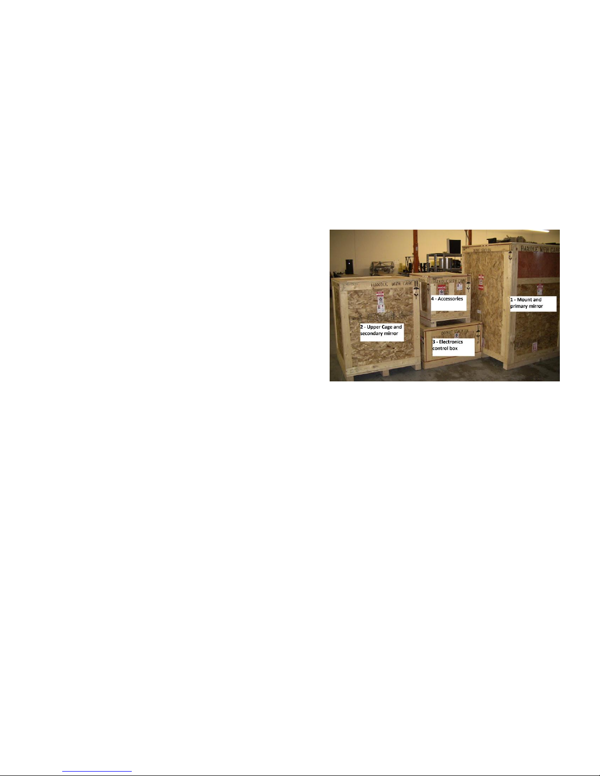
Unpacking ................................................................................................................................................................................................................. 3
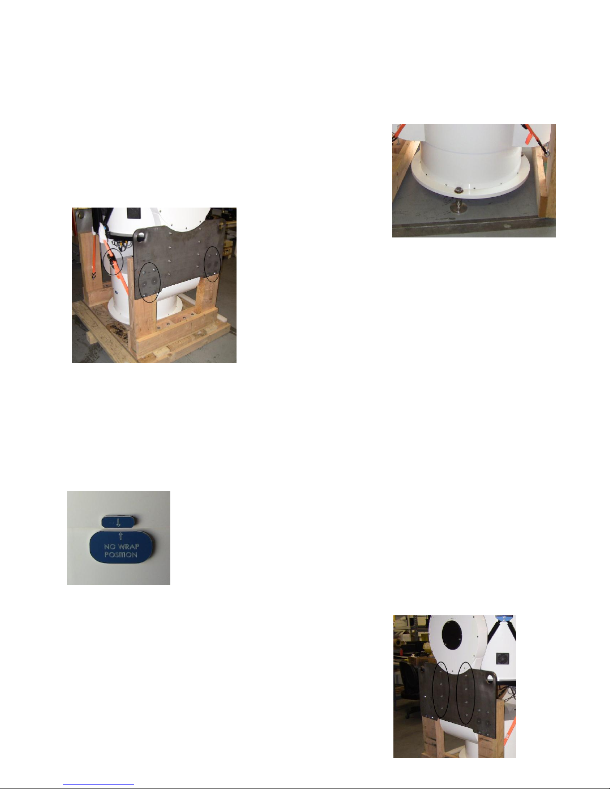
Unpacking the Mount..................................................................................................................................................................................... 4
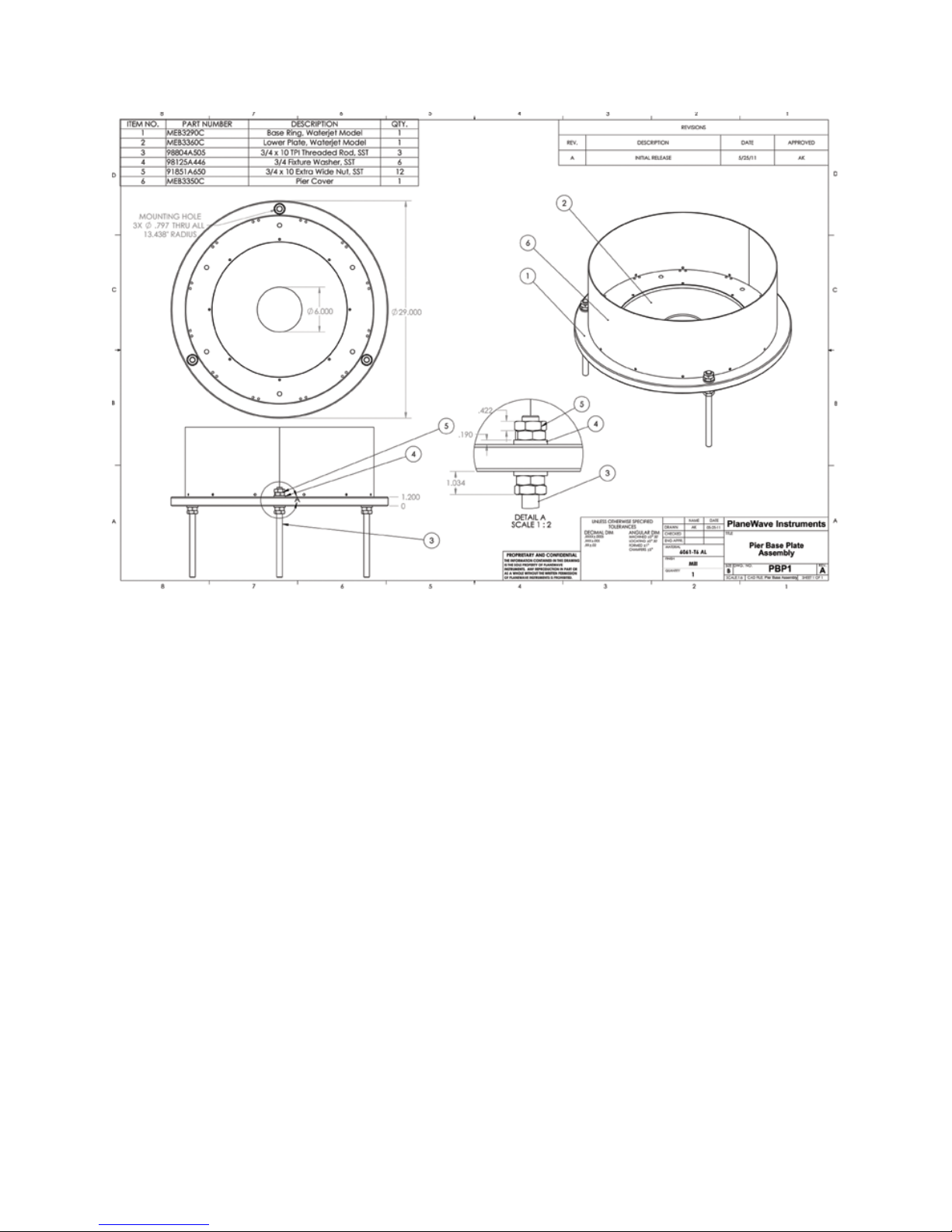
Installation ................................................................................................................................................................................................................ 6
Electronic Panel Housing Dimensions ....................................................................................................................................................................... 9
Software Installation ............................................................................................................................................................................................... 10
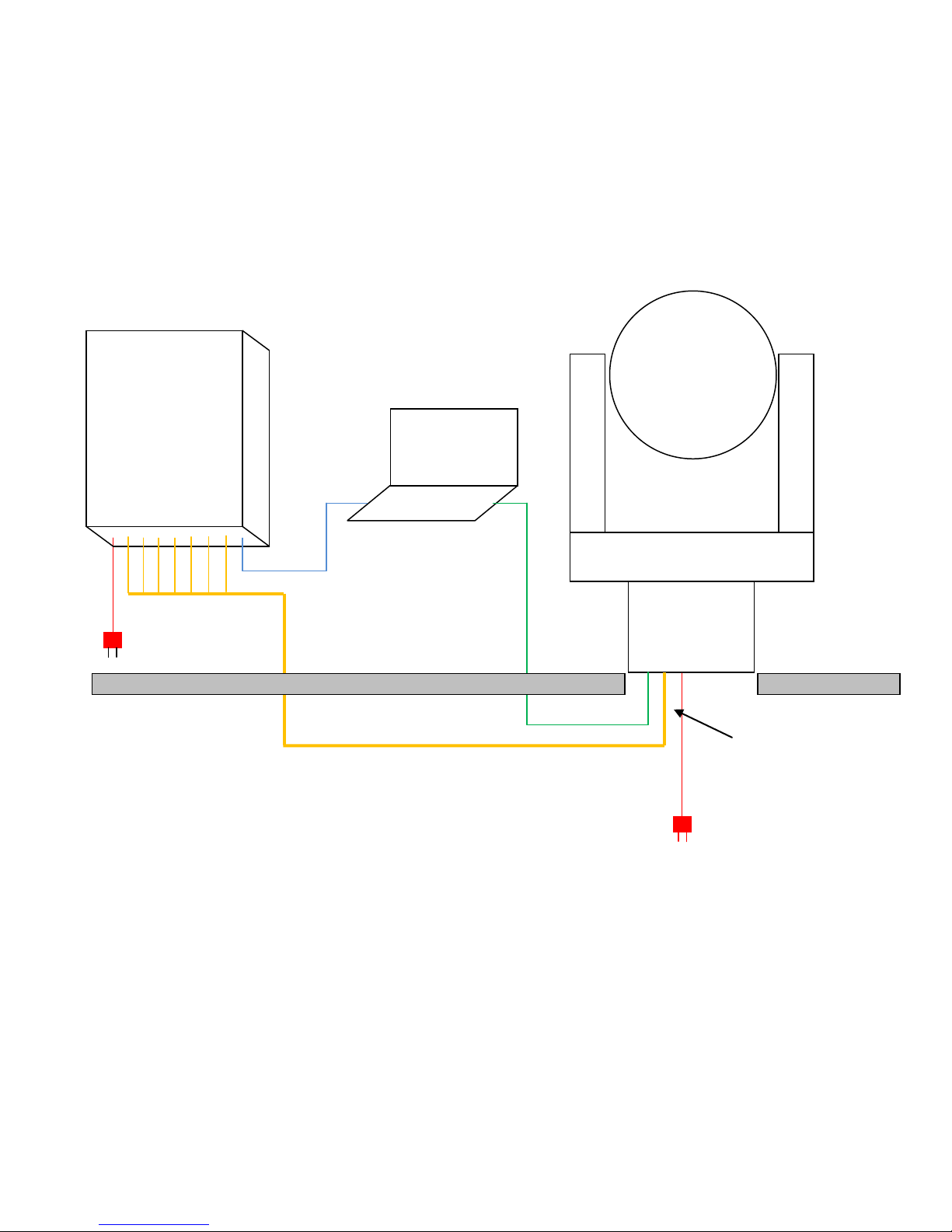
Connecting the Mount to the Control Panel Box..................................................................................................................................................... 11
Connecting the Computer to the Control Panel Box and to the on-board Accessories ........................................................................................... 12
Connecting the CDK700 to PWI............................................................................................................................................................................... 13
Software Overview.................................................................................................................................................................................................. 14
Creating a Mount Model ......................................................................................................................................................................................... 18
Observing Session with Existing Mount Model ....................................................................................................................................................... 18
Collimation .............................................................................................................................................................................................................. 18
Focusing .................................................................................................................................................................................................................. 19
Rotating Tertiary (Optional Accessory).................................................................................................................................................................... 19
Using Two Focusers................................................................................................................................................................................................. 19
Back Focus according to REV F, 3/17/11 ................................................................................................................................................................. 19
VISUAL ADAPTER, 700399 (7003991 AND 7003992).......................................................................................................................................... 20
2” Feather Touch Adapters for CDK700 ............................................................................................................................................................. 20
APOGEE IMAGE TRAIN with Alta Body, AFW50 Filter Wheel, and Monster MOAG...................................................................................... 21
APOGEE IMAGE TRAIN with Alta D9 Body and AFW50 Filter Wheel............................................................................................................. 21
APOGEE IMAGE TRAIN with Alta D9 Body .................................................................................................................................................... 21
SBIG STL IMAGE TRAIN WITH INTERNAL FILTER WHEEL ............................................................................................................................... 21
FLI ProLine Body and CFW3(.848) or CFW5 (.848) and MMOAG .................................................................................................................. 22
FLI ProLine Body and CFW3(.848) or CFW5 (.848) and MMOAG .................................................................................................................. 22
SBIG STL IMAGE TRAIN with MOAG.............................................................................................................................................................. 22
Specifications .......................................................................................................................................................................................................... 22
Wiring Diagrams ................................................................................................................................................................................................ 22