Ohio Medical Corporation SM30B User manual

Operating Instructions
SM30B - SM250B
Motor Mounted
Liquid Ring Vacuum Pumps
It is imperative to read the operating instructions prior
to commissioning!
is document as well as all documents included in the
appendix is not subject to any update service!
Subject to technical changes.
Issue:
01/2014
Doc./ Item no.:
255548 Rev.1

2 255548 Rev.1
Index
1 Important basic information ............................................... 4
1.1 Target groups ......................................................................5
1.2 Applicable documents ....................................................... 5
1.3 Warnings and symbols ...................................................... 6
1.4 Terminology........................................................................ 6
2 Safety ...................................................................................... 7
2.1 Intended use........................................................................ 7
2.2 Potential misuse.................................................................. 7
2.3 General safety instructions ............................................... 7
2.3.1 Product safety .................................................................. 7
2.3.2 Obligations of the operator............................................ 8
2.3.3 Obligations of the sta.................................................... 8
2.4 Residual risks......................................................................8
2.5 Special risks.........................................................................8
2.5.1 Potentially explosive area...............................................8
2.5.2 Dangerous media to be pumped................................... 8
3 Design and functioning...................................................... 9
3.1 Marking ............................................................................... 9
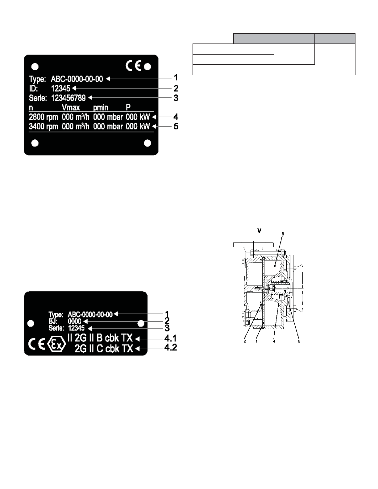
3.1.1 Nameplate ........................................................................ 9
3.1.2 ATEX plate....................................................................... 9
3.1.3 Pump type code............................................................... 9
3.2 General description............................................................9
3.3 Design and functional principle..................................... 10
3.4 Sha sealing ......................................................................10
3.4.1 Mechanical seal .............................................................10
4 Transport, storage and disposal......................................11
4.1 Transport...........................................................................11
4.1.1 Unpacking and inspection on delivery ......................11
4.1.2 Manual transport ..........................................................11
4.1.3 Transport with liing gear ...........................................11
4.2 Storage ...............................................................................11
4.3 Preservation ......................................................................12
4.3.1 Preservation inside the system ....................................12
4.3.2 Preservation outside the system..................................12
4.4 Removing preserving agent ............................................13
4.5 Disposal ............................................................................. 13
5 Set-up and connection ......................................................14
5.1 Preparing set-up...............................................................14
5.1.1 Checking ambient conditions......................................14
5.1.2 Minimum clearances for heat dissipation..................14
5.1.3 Preparing installation site ............................................14
5.1.4 Preparing foundation and surface ..............................14
5.1.5 Removing preserving agent ......................................... 14
5.2 Set-up with foundation....................................................14
5.2.1 Placing aggregate on foundation.................................14
5.2.2 Fixing aggregate.............................................................15
5.3 Set-up without foundation..............................................15
5.4 Set-up on level surface/frame.........................................15
5.5 Planning pipe system.......................................................15
5.5.1 Dimensioning supports and connections..................15
5.5.2 Specifying nominal diameter.......................................16
5.5.3 Specifying pipe lengths................................................. 16
5.5.4 Changes in cross-section and direction .....................16
5.5.5 Safety and control devices............................................16
5.6 Connecting pipes .............................................................16
5.6.1 Providing for clean piping............................................ 16
5.6.2 Installing suction pipe .................................................. 16
5.6.3 Installing pressure pipe.................................................16
5.6.4 Stress-free pipe connection.......................................... 16
5.7 Electrical connection .......................................................17
5.7.1 Motor connection .........................................................17
5.7.2 Checking direction of rotation....................................17
6 Operation ............................................................................17
6.1 Preparations for commissioning....................................17
6.1.1 Identifying pump type..................................................17
6.1.2 Removing preserving agent ......................................... 17
6.1.3 Checking shut-down period........................................17
6.1.4 Filling..............................................................................17
6.2 Commissioning ................................................................17
6.2.1 Switch-on .......................................................................17
6.2.2 Switch-o .......................................................................18
6.3 Setting the operating liquid ow rate ............................18
6.3.1 Continuous-ow cooling .............................................18
6.3.2 Open circulation cooling .............................................19
6.3.3 Closed circulation cooling ...........................................19
6.4 Decommissioning ............................................................19
6.5 Re-commissioning ...........................................................20
6.6 Operating stand-by aggregate.........................................20
7 Maintenance and servicing ..............................................20
7.1 Monitoring ........................................................................20
7.2 Rinsing o contaminations.............................................21
7.2.1 Minor ne-grained contamination.............................21
7.2.2 Major ne-grained contamination .............................21
7.3 Prevention of corrosion and deposits............................21
7.4 Disassembly ......................................................................21
7.4.1 Return to manufacturer................................................21
7.4.2 Spare parts...................................................................... 22
7.4.3 Aggregate repairs...........................................................22
7.4.5 Disassembly of SM30....................................................22
7.4.6 Disassembly of SM55-250B .........................................22
7.5 Assembly ...........................................................................23
7.5.2 Assembly of SM30B ......................................................23
7.5.3 Assembly of SM55-250B ..............................................24

3 255548 Rev.1
8 Troubleshooting................................................................. 26
9 Technical data.....................................................................28
9.1 Operating limits ...............................................................28
9.1.1 Media to be pumped.....................................................28
9.1.2 Switching frequency......................................................28
9.2 General technical data.....................................................28
9.2.1 Weight.............................................................................28
9.2.2 Sound level.....................................................................28
9.2.3 Drive power ...................................................................28
9.2.4 Operating liquid............................................................29
9.2.5 Medium to be pumped................................................. 29
9.2.6 Operating connections.................................................29
9.2.7 Mechanical seal .............................................................29
9.2.8 Ambient conditions ...................................................... 30
9.2.9 Clearances for heat dissipation....................................30
9.2.10 Tightening torques......................................................30
9.3 Conical pipe ttings.........................................................31
9.4 Permissible forces acting on pump nozzles ..................31
9.5 Preserving agents..............................................................31
9.5.1 Preservation lling volumes ........................................31
9.6 Test pressure for pressure test.........................................31
9.7 Accessories ........................................................................ 31
10 Appendix ...........................................................................32
10.3 Dimensional drawing SM30B.......................................32
10.4 Cross-sectional drawing SM30B.................................. 33
10.5 Dimensional drawing SM55-100B...............................34
10.6 Cross-sectional drawing SM55-SM75B ...................... 35
10.7 Cross-sectional drawing SM100B................................36
10.8 Dimensional drawing SM200B-250B..........................37
10.9 Cross-sectional drawing SM200B-250B .....................38
10.17 Certicate of conformity.............................................39

4 255548 Rev.1
1 Important basic information
ese operating instructions form part of the technical
Documentation of the system in accordance with the EC
machinery directive.
ese operating instructions comply with machinery
directive 2006/42/EC of the European Parliament and the
Council on the approximation of the laws, regulations and
administrative provisions of the Member States relating to
machinery, Appendix I, Paragraph 1.7.4.
ese operating instructions are addressed to the person in
charge of the plant, who is obliged to provide them to the
sta responsible for system set-up, connection, operation
and maintenance.
He must ensure that all information included in the
operating instructions and the enclosed documents have
been read and understood.
e operating instructions must be kept at a designated and
easily accessible place and consulted at the slightest doubt.
e manufacturer does not accept liability for damage to
persons, animals, objects or the system itself incurred by
improper use, non-observance or incomplete observance
of the safety precautions included in these operating
instructions or by modications to the system or use of
improper spare parts.
Duplication or transfer of these operating instructions to
third parties requires written approval of the manufacturer.
is also applies to the duplication or transfer of excerpts
of these operating instructions and to the transfer of these
operating instructions in digital form.
ese instructions
• form part of the pump/aggregate.
• apply to all series mentioned herein.
• describe safe and proper operation during all
operational phases.
• must be stowed safely throughout the entire service life
of the machine.
• must be handed over to future owners of the machine.
Scope of supply
• Liquid ring vacuum pump (closed coupled version)
• Operating Instructions
• Base plate (optional)
• Accessories (optional):
− separator
− gas ejector
− ball check valves
− vacuum check valve
− drainage valve
Technical support address
Ohio Medical Corporation
1111 Lakeside Drive
Gurnee, IL 60031
800-448-0770
servicedept@ohiomedical.com
Warranty and liability
Warranty and liability claims arising from personal injury
and material damage are excluded if one of the following
conditions applies:
• improper use of the liquid ring vacuum pump
• improper mounting, commissioning, operation and
maintenance of the liquid ring vacuum pump
• operation of the liquid ring vacuum pump despite
defective safety devices
• non-observance of the notes in the operating
instructions
• unauthorized constructional changes to the liquid ring
vacuum pump
• inadequate maintenance, repair and servicing measures
• catastrophic events caused by foreign bodies or acts of
God

5 255548 Rev.1
1.1 Target groups
Target Group Task
Operator ▶
▶
▶
Keep these instructions available at the location of the system, also for later
consultation.
Advise sta to read and observe these instructions and the provided
documents, particularly the safety precautions and warnings.
Observe additional provisions and regulations related to the system.
Qualied sta, assembler
▶ Read, observe and adhere to these operating instructions and all applicable
documents, particularly the safety precautions and warnings.
Tab. 1 Target groups and their tasks
1.2 Applicable documents
Document Purpose
ATEX additional instructions Operation in potentially explosive areas (only applicable to vacuum pumps
designed for use in potentially explosive areas)
Declaration of conformity Conformity with standards
Tab. 2 Applicable documents

6 255548 Rev.1
1.3 Warnings and symbols
Warning Security level Consequences of non-observances
imminently hazardous situation death, severe personal injuries
potentially hazardous situation death, severe personal injuries
potentially dangerous situation minor personal injuries
potentially dangerous situation material damage
Tab. 3 Warnings and consequences of non-observance
Symbol Meaning
Safety sign
▶ Observe all measures marked with the safety sign to avoid
personal injuries or death.
Safety sign
▶ Observe all measures marked with the safety sign to avoid
personal injuries or death by electric shock.
▶ Instruction for action
1. , 2. , … Multi-step instruction for action
✓Pre-requisite
→Cross-reference
Information, note
Tab. 4 Symbols and meaning
1.4 Terminology
Term Meaning
Pump Liquid ring vacuum pump without drive, components or accessories
Aggregate Complete liquid ring vacuum pump including pump, drive, components and
accessories
Auxiliary operating systems Devices for operating the vacuum pump aggregate
Separator Device for separating gaseous from liquid media
Gas ejector Device for operating the vacuum pump aggregate for deep vacuum
Vacuum check valve Device for limiting the created vacuum
Drainage valve Device for limiting the lling level in the vacuum pump
Tab. 5 Terminology and meaning
WARNING
CAUTION
CAUTION
DANGER

7 255548 Rev.1
2 Safety
e manufacturer does not accept liability for
damage resulting from non-observance of the overall
documentation.
2.1 Intended use
• Observe all provisions included in the operating
instructions.
• Observe all safety instructions.
• Comply with inspection and maintenance intervals.
• Use the aggregate exclusively for delivery of the
permissible media to be pumped (→ General technical
data, page 28).
• Operate the aggregate with permissible operating liquid
only (→ General technical data, page 28).
• Observe the operating limits (→ Operating limits, page
28).
• Prevent dry running:
− e sealing rings of the mechanical seals will be
damaged within only few seconds.
− Ensure that the aggregate is only operated with
sucient operating liquid, never without operating
liquid.
• Prevent cavitation:
− Install a vacuum check valve.
− Comply with the temperature limits of the operating
liquid and the medium to be pumped.
− Observe the limit values for inlet pressure and
pressure dierence.
− Do not operate the pump when the tting in the
suction pipe is closed.
• Prevent overheating:
− Do not operate the aggregate when ttings are closed.
• Prevent motor damage:
− Observe the maximum ow rate for delivery of
liquids.
− Observe the switching frequency of the aggregate.
− e motor protection switch must not be set to a
value above nominal current.
• Any use other than the intended use must be agreed
with the manufacturer.
2.2 Potential misuse
• Observe the operating limits of the aggregate
concerning temperature, pressure, speed, density and
viscosity (→ Operating limits, page 28).
• e higher the density of the operating liquid, the
higher the motor power consumption. Observe the
permissible density to protect the aggregate against
overload.
• When delivering solid laden liquids, observe the solid
content limit values (→ General technical data, page 28).
• Do not combine multiple limit values (→ Operating
limits, page 28).
• Prevent sudden pressure changes of the gas to be
extracted.
• Prevent sudden temperature changes of the gas to be
extracted or operating liquid.
• Do not use in rooms where explosive gases may
be present unless the aggregate has been expressly
intended for such purpose.
• Do not extract, deliver or compact explosive,
inammable, aggressive or toxic media unless the
aggregates have been expressly intended for such
purpose.
• Unauthorized opening of the aggregate results in the
forfeiture of any and all claims for defects.
2.3 General safety instructions
e following provisions must be observed prior to
executing any works.
2.3.1 Product safety
e pump/aggregate has been designed in accordance with
state-of-the-art technology and the generally acknowledged
rules on safety. Yet, operation of this pump/aggregate may
present a threat to the life or physical health of the user
or third parties and impair the pump/aggregate and other
property.
• Only operate the pump/aggregate in a technically
awless condition and in accordance with the
provisions, safety precautions and warnings included in
these operating instructions.
• Keep these operating instructions as well as all supplied
documents complete and legible and ensure that they
can be accessed by sta at all times.
• Refrain from any operating methods which may put
sta or uninvolved third parties at risk.
• In case of defects having safety implications: shut down
the aggregate immediately and consult the person in
charge to rectify the defect.
• In addition to the overall documentation, all legal or
other safety and accident prevention regulations as
well as all applicable standards and guidelines of the
respective country of operation must be observed.

8 255548 Rev.1
2.3.2 Obligations of the operator
2.3.2.1 Safety-conscious working
• Only operate the aggregate in a technically awless
condition and in accordance with the provisions, safety
precautions and warnings included in these operating
instructions.
• Ensure and verify compliance with:
− intended use
− legal or other safety and accident prevention
regulations
− safety regulations applying to handling hazardous
substances
− applicable standards and guidelines of the respective
country of operation
• Provide for protective equipment.
2.3.2.2 Sta qualication
• Ensure that sta involved in aggregate operation has
read and understood these operating instructions
and all applicable documents, particularly all safety,
maintenance and servicing information, prior to
starting work.
• Dene clear roles and responsibilities and arrange for
sta monitoring.
• All works must only be carried out by technically
qualied sta:
− assembly, servicing, maintenance works
− works on electrical equipment
• Sta undergoing training must only work on the
aggregate under the supervision of technically qualied
sta.
2.3.2.3 Safety devices
• Provide for the following safety devices and ensure their
proper functioning:
− for hot, cold and moving parts: on-site protection
against contact with the aggregate
− when electrostatic charging is likely to occur: provide
for grounding
2.3.2.4 Warranty
• During the warranty period, conversion works, repairs
and modications are subject to approval by the
manufacturer.
• Use original parts or parts approved by the
manufacturer only.
• All warranty and damage claims will expire in case of
nonobservance of these operating instructions.
2.3.3 Obligations of the sta
• Notes attached to the aggregate must be observed and
kept legible, e.g. arrows indicating the direction of
rotation, symbols indicating uid connections.
• Guards for protection against contact with hot, cold and
moving parts must not be removed during operation.
• If required, use protective equipment.
• Do not expose parts of the body to the vacuum.
• Works on the aggregate must only be carried out at
standstill.
• Prior to carrying out any assembly or maintenance
works, de-energize the motor and protect it against
restart.
• Having completed all works on the aggregate, duly
reassemble the safety devices.
2.4 Residual risks
Long and loose hair may become entangled in the
protective covers of the motor and the sha coupling.
▶ Wear a hairnet!
Risk of injuries caused by ying objects, which were
inserted in the openings of the motor fan cover or in the
openings of the coupling protection!
▶ Do not insert any objects!
Risk of burns/scalds when getting in contact with hot
surfaces or hot media!
▶ Do not touch!
▶ Wear protective gloves!
Risk of injuries caused by operating liquid escaping from
a defective mechanical seal!
▶ Shut down the pump!
▶ Repair the pump!
2.5 Special risks
2.5.1 Potentially explosive area
(→ ATEX additional instructions)
2.5.2 Dangerous media to be pumped
• When dealing with dangerous media to be pumped
(e.g. hot, inammable, explosive, toxic, hazardous
to health), observe the safety regulations applying to
handling hazardous substances.
• Use protective equipment when carrying out any works
on the aggregate.
WARNING

9 255548 Rev.1
3 Design and functioning
3.1 Marking
3.1.1 Nameplate
1. Type designation
2. Item identication number (pump / aggregate)
3. Serial number
4. Delivery data at 50 Hz
Nominal speed
Maximum suction volume
Minimum inlet pressure
Power requirements
5. Delivery data at 60 Hz
Nominal speed
Maximum suction volume
Minimum inlet pressure
Power requirements
Fig. 1 Nameplate (example)
3.1.2 ATEX plate
1. Type designation
2. Year of manufacture
3. Serial number
4.1 Explosion protection mark: aggregate inside
4.2 Explosion protection mark: aggregate outside
Fig. 2 ATEX plate (example)
3.1.3 Pump type code
V 155 55
1
2
3
1. Series
2. Size
3. Material design code
Tab. 6 Pump type code (example)
3.2 General description
e pumps of the SM series are horizontal, single-stage
liquid ring vacuum pumps with radial inlet and outlet.
e internal control of the gas to be pumped is realized by
means of inter casings (1) with control slots and additional
valve technology (2).
e electrical drive is modularly screwed to the pump
(aggregate). A maintenance-free mechanical seal (4) in the
sha sealing casing is used to seal the sha.
e aggregates of the SM series are able to deliver low liquid
ow rates. e discharged operating liquid can be re-used
when using a separator.
1. Inter casing
2. Valves
3. Pump cover with integrated inter casing
4. Mechanical seal
5. Motor/pump sha
6. Impeller
Fig. 3 Description of pump type SM

10 255548 Rev.1
3.3 Design and functional principle
e pump is operated in accordance with the liquid ring
principle. e impeller is positioned o-center in the
cylindrical pump casing. It transfers the drive power to a
liquid ring, which forms concentrically to the casing when
the pump is started.
e gaseous medium remaining in the casing is distributed
around the impeller due to the lower density in the hub
area. As the impeller is positioned o-center to the casing,
the available space for the gas between the surface of the
liquid and the hub becomes crescent-shaped.
is way, the remaining space for the gas between the
blades expands and shrinks during each rotation.
1. Suction opening
2. Pressure opening
3. Liquid ring
Fig. 4 Functional principle of liquid ring vacuum pumps
e arrangement of suction and pressure openings in
the inter casing allows for the suction, compression and
discharge of gas. e liquid both serves the sealing between
the individual impeller chambers and the absorption of heat
produced during compression.
e pump must be permanently supplied with operating
liquid during operation as a portion of the liquid
continuously escapes from the pump together with the gas.
e discharged operating liquid can be separated from the
gas by means of a downstream separator and re-used.
3.4 Sha sealing
3.4.1 Mechanical seal
Mechanical seals may slightly leak for functional reasons.
• Single mechanical seal, unbalanced, dependent on the
direction of rotation with conical spring

11 255548 Rev.1
4 Transport, storage and disposal
e following accident prevention regulations have to
be observed prior to following transport and handling
regulations:
− BGV D8 winches, liing and pulling devices
− BGV D6 load liing devices
4.1 Transport
4.1.1 Unpacking and inspection on delivery
1. Unpack the aggregate on delivery and inspect it for
transport damage.
2. Report any transport damage to the manufacturer
immediately.
3. Dispose of packaging material according to local
regulations.
4.1.2 Manual transport
Risk of injuries caused by liing heavy loads!
Observe the permissible weights for liing and carrying
machine components.
Type Sex Age Rate per shi
CAUTION
4.1.3 Transport with liing gear
DANGER
Risk of death or contusions from falling goods to be
transported!
▶ Select liing gear in accordance with the total weight to
be transported.
▶ Transport the aggregate in horizontal position only.
▶ Never suspend the aggregate to the ring lug of the
motor.
▶ Attach the liing gear in accordance with the following
gures.
▶ Do not stand under suspended loads.
Fig. 5 Attaching liing gear to the aggregate
▶ Li the aggregate accordingly.
4.2 Storage
Pumps/aggregates treated by the factory have been provided
with an anticorrosive coating. When properly stored
indoors, the pump/aggregate is protected for a maximum
of 3 months. In case of longer storage periods, the pump/
aggregate has to be treated with a preserving agent again (→
4.3 Preservation).
For storing pumps/aggregates which have already been
in use, the preparations specied in Paragraph 4.3
Preservation must be made.
Applied preserving agents (→ page 31)
rarely
< 5%
repeat-
edly
5 - 10%
fre-
quently
> 10-
35%
[Years] [kg] [kg] [kg]
Liing Men - 16
17 - 19
20 - 45
>45
20
35
55
50
13
25
30
25
-
20
25
20
Liing Women -16
17-19
20 - 45
>45
13
13
15
13
9
9
10
9
-
8
9
8
Carrying Men - 16
17 - 19
20 - 45
>45
20
30
50
40
13
20
30
25
-
15
20
15
Carrying Women - 16
17 - 19
20 - 45
>45
13
13
15
13
9
9
10
9
-
8
9
8
Liing
and car-
rying
Expectant
Mothers
10 (5)
(legal
dra)
5 (legal
dra)
Source: Bavarian State Oce for Occupational Safety, Occupa-
tional Medicine and Safety Technology
Tab. 7 Maximum weights for manual liing
▶ Suitable liing gear and means of transport must be
used for components exceeding the max.weights!

12 255548 Rev.1
Risk of material damage caused by improper storage!
▶ Properly apply preserving agent to the inside and
outside of the aggregate.
1. Select a preserving agent in accordance with the type
and duration of storage (→ page 31).
2. Use preserving agents in accordance with the
manufacturer’s specications.
3. Coat all bare metal components positioned inside and
outside the pump with preserving agent.
4. Treat the impeller gap with a preserving agent.
4.3.1 Preservation inside the system
Risk of material damage caused by improper storage!
▶ Store the aggregate accordingly.
CAUTION
1. Close all openings with blank anges, plugs or plastic
covers.
2. Make sure the storage room meets the following
conditions:
− dry
− frost-free
− vibration-free
− protected
− constant humidity
3. Turn the motor sha once per month.
4. Make sure the motor sha and bearing change their
rotational position in this process.
4.3 Preservation
Not necessary for rust-proof material
CAUTION
Risk of material damage caused by improper
preservation!
▶ Shut down the aggregate (→ Shut-down, page 19).
Use appropriate collecting trays. Position of drainage
bores (Ue) (→ Dimensional drawings, page 32 et seq.).
• Unscrew the screw plugs of all drainage bores (Ue).
• Drain the operating liquid (water).
• Occasionally rotate the motor sha towards the
direction of rotation of the aggregate.
• Continue with this process until no more liquid
escapes.
CAUTION
• Plug all drainage bores with screw plugs.
• Remove the pipes from the suction, pressure and
process water connections.
• Plug the outlet nozzle and the process water connection
by means of blank anges/screw plugs.
• Fill in preserving agent into the open inlet nozzle.
Observe the lling volumes (→ Filling volumes
preservation, page 31).
• Plug the inlet nozzle with a blank ange/screw plugs.
• Switch the aggregate shortly on and o to allow for a
proper distribution of the preserving agent.
• Unscrew the screw plugs of all drainage bores (Ue) and
the operating liquid connection (UB).
• Drain the preserving agent into collecting trays.
• Occasionally rotate the motor sha towards the
direction of rotation of the aggregate.
• Continue with this process until no more preserving
agent escapes.
• Close the suction, pressure and operating liquid
connection (UB) using transport or sealing covers.
• Plug all drainage bores (Ue) with screw plugs.
4.3.2 Preservation outside the system
Risk of material damage caused by improper
preservation!
▶Shut down the aggregate (→ Shut-down, page 19; Return
to manufacturer, page 21).
Use appropriate collecting trays. Position of drainage
bores (Ue) (→ Dimensional drawings, page 32 et seq.).
• Plug all drainage bores (Ue) with screw plugs.
• Close the operating liquid connection (UB) using a
blank ange/screw plug.
• Fill in preserving agent into the open inlet or outlet
nozzle until the agent becomes visible. Observe the
lling volumes (→Filling volumes preservation, page
31).
• Occasionally rotate the motor sha towards the
direction of rotation of the aggregate.
• Continue this process until the preserving agent
appears approx. 30 mm below the upper edge of the
inlet/outlet nozzle.
• Unscrew the screw plugs of all drainage bores (Ue) and
the operating liquid connection (UB).
• Drain the preserving agent into collecting trays.
• Occasionally rotate the motor sha towards the
direction of rotation of the aggregate.
CAUTION

13 255548 Rev.1
Risk of seal damage caused by improper cleaning agents!
▶ Ensure that cleaning agents do not harm the seals.
1. Use cleaning agents which are appropriate for your
respective application.
2. Rinse o preserving agent and collect it together with
the rinsing agent.
3. Dispose of preserving agent according to local
regulations.
4. For storage periods exceeding 6 months:
− Replace elastomer components made of EP rubber
(EPDM).
− Check all elastomer components (O-rings, sha
sealings) for proper elasticity and replace if required.
CAUTION
• Continue with this process until no more preserving
agent escapes.
• Close the suction, pressure and operating liquid
connection (UB) using transport or sealing covers.
• Plug all drainage bores (Ue) with screw plugs.
4.4 Removing preserving agent
Only required for aggregates treated with preserving
agent.
Risk of bearing damage caused by excessive water
pressure or splash water!
▶ Do not treat bearing areas with water or steam jet.
CAUTION
4.5 Disposal
Risk of intoxication and environmental damage caused
by media to be pumped!
▶ Prior to disposing the aggregate:
− Collect escaping media to be pumped and dispose of
separately in accordance with local regulations.
− Neutralize residues of media to be pumped in the
aggregate.
− Disassemble plastic parts and dispose of in
accordance with local regulations.
▶ Assign an authorized company to dispose of the
aggregate to prevent the risk of environmental damage!
WARNING

14 255548 Rev.1
5 Set-up and connection
For aggregates in potentially explosive areas
(→ ATEX additional instructions)
Risk of material damage caused by contamination!
▶ Do not remove transport locks until immediately before
setting up the aggregate.
▶ Do not remove covers, transport and sealing caps until
immediately before connection of the pipes to the
aggregate.
5.1 Preparing set-up
5.1.1 Checking ambient conditions
▶ Make sure the required ambient conditions are
maintained (→Ambient conditions, page 30).
For pump/aggregate set-up at an altitude of > 1000 m above
sea level, consult the manufacturer.
5.1.2 Minimum clearances for heat dissipation
Minimum clearances
(→ Clearances for heat dissipation, page 30)
5.1.3 Preparing installation site
▶ Make sure the installation site meets the following
conditions:
− the aggregate is freely accessible from all sides
− sucient space for installing/disassembling the
pipes as well as for maintenance and repair works,
particularly for installation/disassembly of the
aggregate, is provided for
− the aggregate is not exposed to external vibrations
(bearing damage)
− frost protection
5.1.4 Preparing foundation and surface
Set-up options:
− with concrete foundation
− with steel foundation frame
− without foundation
▶ Make sure foundation and surface meet the following
conditions:
− level
− clean (free of oil, dust or other contaminations)
− load carrying capacity is in accordance with the dead
weight of the aggregate and all operating forces
− adequate aggregate stability
− with concrete foundation:
standard concrete of strength class B 25
5.1.5 Removing preserving agent
▶ If the aggregate is commissioned directly aer set-up
and connection: remove preserving agent prior to set-
up (→ Removing preserving agent, page 13).
5.2 Set-up with foundation
Only possible with base plate
Risk of material damage caused by distortion of the base
plate!
▶ Position and x the base plate on the foundation as
follows.
5.2.1 Placing aggregate on foundation
✓ Auxiliary means, tools, material:
− foundation bolts (→ Set-up drawing)
− steel washers
− non-shrinking mortar grout
− spirit level
1. Li the aggregate (→ Transport, page 11).
2. Hook the foundation bolts from below into the base
plate xing holes.
Observe the manufacturer’s specications when using
adhesive anchors.
3. Place the aggregate on the foundation. Insert the
foundation bolts into the provided anchoring holes.
CAUTION
CAUTION
Fig. 6 Set-up with foundation
4. Use steel washers to align the aggregate to height and
system dimensions as follows:
− Place 1 steel washer (2) at the le and right hand side
of each foundation bolt (1).
− With > 750 mm clearances between the anchoring
holes, an additional steel washer (3) must be
positioned in the middle of each side of the base
plate.
5. Make sure the steel washers are in surface contact with
the base plate.
6. Use the integrated spirit level to check whether the
aggregate is level end to end and side to side with a
maximum allowable tilt of 1 mm/m.
7. Repeat this process until the base plate has been
correctly aligned.

15 255548 Rev.1
5.2.2 Fixing aggregate
Filling the base plate with mortar grout improves the
dampening behaviour.
1. Fill the anchoring holes with mortar grout.
2. When the mortar grout has set, bolt down the base plate
with the specied torque at three points (→ Tightening
torques, page 30).
3. Before tightening the remaining bolts, compensate
for any unevenness in the surface using metal spacing
shims next to each bolt.
4. Make sure the base plate is not distorted.
5.3 Set-up without foundation
With base plate
✓ Auxiliary means, tools, material:
− wrench
− spirit level
1. Hexagon nut
2. Hexagon nut
3. Levelling foot
Fig. 7 Set-up without foundation
1. Li the aggregate (→ Transport with liing gear, page
11).
2. Mount the four levelling feet as illustrated.
3. Position the aggregate on the surface.
4. Adjust the base plate height by means of the levelling
feet as illustrated above:
− Use the wrench to hold the hexagon nut at the
levelling foot (3).
− Loosen the hexagon nut (1).
− e height can be adjusted by turning the hexagon
nut (2).
− Tighten the hexagon nut (1) (→ Tightening torques,
page 30).
− Use the integrated spirit level to check whether the
aggregate is level end to end and side to side with a
maximum allowable tilt of 1 mm/m.
− Repeat this process until the base plate has been
correctly aligned.
5.4 Set-up on level surface/frame
Only possible with motor feet
✓ Auxiliary means, tools, material:
− wrench
1 Frame
Fig. 8 Set-up with motor feet
1. Li the aggregate (→ Transport with liing gear, page
11).
2. Mount the motor feet as illustrated (→ Dimensional
drawings, page 32 et seq.).
3. Position the aggregate on a torsion-resistant level
surface/frame.
4. Screw the aggregate to the surface/frame.
5.5 Planning pipe system
5.5.1 Dimensioning supports and connections
Risk of material damage if the pipes apply excessive
forces and torques to the aggregate!
▶ Make sure the permissible values are complied with (→
DIN ISO 9908).
1. Calculate the piping forces and observe all operating
conditions:
− cold/warm
− empty/lled
− depressurized/pressurized
− position changes
2. Make sure the pipe supports have permanent low-
friction properties and do not seize up due to corrosion.
3. If required, provide for pipe compensators.
CAUTION

16 255548 Rev.1
5.5.2 Specifying nominal diameter
Size of suction/pressure connections (→ Operating
connections, page 29)
▶ Keep the ow resistance in the pipes as low as possible.
1. Nominal suction pipe diameter ≥ nominal suction
connection diameter
2. Nominal pressure pipe diameter ≥ nominal pressure
connection diameter.
5.5.3 Specifying pipe lengths
1. Dimension the suction, pressure and operating liquid
pipes as short as possible.
2. Increase the pipe cross-sections when using long
suction, pressure and operating liquid pipes.
e pressure pipe must not rise more than 1 vertically
or diagonally upwards.
5.5.4 Changes in cross-section and direction
1. Avoid radii of curvature of less than 1.5 times the
nominal pipe diameter.
2. Avoid sudden changes of cross-section and direction
along the piping.
5.5.5 Safety and control devices
5.5.5.1 Avoiding contamination
1. Integrate low-resistance lters in the suction pipe.
2. Install a dierential pressure gauge with contact
manometer to monitor the contamination process.
5.5.5.2 Avoiding backow
▶ Install a ball check valve between the suction pipe and
the suction connection of the aggregate to prevent
operating liquid from owing back into the suction pipe
aer aggregate shut-down.
5.5.5.3 Provisions for isolating and shutting o pipes
For maintenance and repair works
▶ Provide for shut-o devices in the suction, pressure and
process water pipes.
5.5.5.4 Provisions for measuring operating conditions
1. Provide for manometers in the suction and pressure
pipe to allow for pressure measuring.
2. Provide for a power sensor at the motor side.
5.6 Connecting pipes
5.6.1 Providing for clean piping
Risk of material damage caused by aggregate
contamination!
▶ Make sure the inside of the aggregate is kept free of
contamination.
1. Clean all piping parts and ttings prior to assembly.
CAUTION
2. Make sure no ange seals project inwards.
3. Make sure no sealing material (sealing tape, adhesive)
projects inwards.
4. Remove any blank anges, plugs, protective foils and/or
protective paint from the anges.
5.6.2 Installing suction pipe
1. Remove transport and sealing covers from the
aggregate.
2. Avoid air pockets: lay out the pipes with a continuous
slope down to the aggregate.
3. Make sure no seals project inwards.
4. Make sure no sealing material (sealing tape, adhesive)
projects inwards.
5. Install a ball check valve in the suction pipe to prevent
operating liquid from owing into the suction pipe at
standstill.
5.6.3 Installing pressure pipe
1. Remove transport and sealing covers from the
aggregate.
2. Install the pressure pipe.
3. e pressure pipe must not rise more than 0.3 m
vertically or diagonally upwards.
4. Avoid air pockets: lay out the pipes with a continuous
slope from the aggregate.
5. Make sure no seals project inwards.
6. Make sure no sealing material (sealing tape, adhesive)
projects inwards.
5.6.4 Stress-free pipe connection
Provide for a stress-free pipe connection in accordance
with VDMA standard sheet 24277.
5.7 Electrical connection
Risk of death from electric shock!
▶ Any electrical works must be carried out by qualied
electricians only.
▶ Observe the IEC 30364 (DIN VDE 0100) and for
potentially explosive areas the IEC 60079 (DIN VDE
0165) standard.
Risk of death from rotating parts!
▶ Make sure to only operate the aggregate with all covers
fan hood) installed.
RISK OF ELECTRIC SHOCK
DANGER

17 255548 Rev.1
DANGER
5.7.1 Motor connection
Observe the manufacturer’s specications for the motor.
1. Connect the motor in accordance with the circuit
diagram.
2. Exclude any risk associated with electric power.
3. Install an Emergency-Stop button.
5.7.2 Checking direction of rotation
Risk of death from rotating parts!
▶ Use protective equipment when carrying out any works
on the aggregate.
▶ Keep an adequate distance to rotating parts.
Risk of material damage caused by dry running or
incorrect direction of rotation!
▶ Pump lled with operating liquid up to the middle of
the sha (→ Filling, page 17).
1. Switch the aggregate on and immediately o again.
2. Check whether the direction of rotation of the motor is
in accordance with the arrow indicating the direction of
rotation on the aggregate.
Wrong direction of rotation may result in damage
and escape of operating liquid at the mechanical seal.
Risk of death from electric shock!
▶ Any electrical works must be carried out by qualied
electricians only.
▶ Observe the IEC 30364 (DIN VDE 0100) and for
potentially explosive areas the IEC 60079 (DIN VDE
0165) standard.
3. In case of deviating direction of rotation: swap the two
phases.
CAUTION
RISK OF ELECTRIC SHOCK
6 Operation
For aggregates in potentially explosive areas
(→ ATEX additional instructions)
6.1 Preparations for commissioning
6.1.1 Identifying pump type
▶ Identify the pump type (→ Nameplate, page 9).
Pump types vary, e.g. with regard to material, suction
capacity, type of sha sealing, auxiliary operating
systems.
6.1.2 Removing preserving agent
Only required for aggregates treated with preserving
agent.
▶ Remove preserving agent
(→ Removing preserving agent, page 13).
6.1.3 Checking shut-down period
▶ Shut-down periods > 1 year: contact the manufacturer
and ask for required measures.
▶ Shut-down periods < 1 year: take all steps as required
for commissioning (→ Commissioning, page 17).
6.1.4 Filling
1. Remove the screw plug from port UV (→ Dimensional
drawing, page 32 et seq.).
2. Fill the pump with operating liquid (water) maximally
up to the middle of the sha.
3. When operating liquid escapes from port UV, stop the
lling process.
4. Screw the screw plug into port UV (→ Dimensional
drawing, page 32 et seq.).
5. Open the suction-side tting.
6. Open the pressure-side tting.
7. Make sure all ports and connections are tight.
6.2 Commissioning
6.2.1 Switch-on
✓ Aggregate correctly set up and connected
✓ Motor correctly connected
✓ All connections stress-free and sealed
✓ Pump/aggregate properly prepared and lled
✓ All safety devices installed and checked for proper
functioning
✓ Pump/aggregate properly prepared and lled
Risk of injuries caused by running aggregate!
▶ Do not touch the running aggregate.
▶ Do not carry out any works on the running aggregate.
DANGER

18 255548 Rev.1
Risk of death from electric shock!
▶ Any electrical works must be carried out by qualied
electricians only.
▶ Observe the IEC 30364 (DIN VDE 0100) and for
potentially explosive areas the IEC 60079 (DIN VDE
0165) standard.
Risk of injuries caused by vacuum or harmful media to be
pumped and operating liquid!
▶ Use protective equipment when carrying out any works
on the aggregate.
Risk of material damage caused by dry running!
▶ Make sure the aggregate has been properly lled.
Risk of cavitation when throttling down the suction ow!
Risk of cavitation when the tting in the suction pipe is
closed!
▶ Completely open the suction-side tting and do not use
it for controlling the ow rate.
▶ Open the pressure-side tting.
Risk of material damage caused by a closed pressure pipe!
▶ Do not operate the aggregate when the pressure-side
tting is closed.
▶ Observe the max.permissible operating limits
(→ Operating limits, page 28).
− max.permissible pressure dierence
− max.permissible compression pressure
− max.permissible operating liquid temperature
− max.permissible operating liquid viscosity
− max.permissible operating liquid density
− max.permissible temperature of the medium to be
pumped
1. Open the pressure-side tting.
2. Ventilation port (if available): open the tting.
3. Switch on the motor.
4. Operating liquid: open the tting.
RISK OF ELECTRIC SHOCK 5. Open the suction-side tting.
6. Ventilation port (if available): close the tting as soon as
the motor has reached its nominal speed.
7. Provide for a smooth running behaviour of the
aggregate.
8. Check the aggregate and connections for tightness.
6.2.2 Switch-o
Risk of injuries caused by vacuum or harmful media to be
pumped and operating liquid!
▶ Use protective equipment when carrying out any works
on the aggregate.
1. Close the tting at the operating liquid side.
2. Switch o the motor.
3. Ventilation port (if available): open the tting.
4. Check all connecting screws and tighten if required
(only aer initial commissioning).
Risk of material damage resulting from vacuum
condition!
▶ Aerate the aggregate during switch-o.
▶ Do not leave the aggregate under vacuum.
If the aggregate is not aerated, the mechanical seals will
be subject to damage.
6.3 Setting the operating liquid ow rate
6.3.1 Continuous-ow cooling
▶ Switch on the aggregate.
▶ Set the pressure in the operating liquid pipe to max. 0.2
bar overpressure (→ Diagram Fig. 9)
WARNING
CAUTION
CAUTION
CAUTION
CAUTION
WARNING
Fig. 9 Continuous-ow cooling

19 255548 Rev.1
6.3.2 Open circulation cooling
▶ Switch on the aggregate.
▶ Set the pressure in the operating liquid pipe to max. 0.2
bar overpressure (→ Diagram Fig. 10, 11, 12)
6.3.3 Closed circulation cooling
▶ Switch on the aggregate.
▶ Set the pressure in the operating liquid pipe to a value
which is 0.1 bar smaller than the compression pressure
(→ Diagram Fig. 13)
Fig. 10 Open circulation cooling
Fig. 11 Open circulation cooling with temperature control
Fig. 12 Open circulation cooling with controlled liquid feed
▶ Observe the permissible operating liquid temperature
(→ Operating limits, page 28)
Fig. 13 Closed circulation cooling
▶ Observe the permissible operating liquid temperature
(→ Operating limits, page 28)
Pos. Meaning
SSuction connection
LVentilation port
DPressure connection
AOverow
UCirculation liquid
FFresh liquid
VK Feed-in cooling agent
RK Return cooling agent
TIC Temperature
PIC Pressure
LIC Filling level
Tab. 8 Legend of symbols
6.4 Decommissioning
Risk of injuries caused by vacuum or harmful media to be
pumped and operating liquid!
▶ Use protective equipment when carrying out any works
on the aggregate.
▶ Reliably collect escaping media to be pumped and
dispose of in an environmentally-friendly way.
WARNING

20 255548 Rev.1
▶ Implement the following measures when taking the
pump/aggregate out of operation:
Aggregate is Measure
shut down while
remaining ready
for operation
▶
Shortly operate (approx. 5
minutes) the aggregate at
intervals of at least one month
but not exceeding 3 months
(→ Commissioning, page 17).
shut down for a
longer period of
time
▶
Implement measures in
accordance with the condition
of the operating liquid (→ Tab.
10 Measures depending on
the behaviour of the operating
liquid)
drained ▶Close all ttings.
disassembled ▶
Disconnect the motor from
the power supply and secure it
against unauthorized switch-on.
stored ▶
Observe the measures to be
implemented for storage
(→ Storage, page 11).
Tab. 9 Measures to be taken when putting the pump out of
operation
Operating
liquid
Duration of shut-down (process-
dependent)
Short Long
Water ▶Drain
aggregate
and
separator.
▶
▶
Drain aggregate and
separator.
Treat aggregate with
a preserving agent (→
Preservation, page 12).
Other
media
▶
▶
Drain aggregate and
separator.
Treat aggregate with
a preserving agent (→
Preservation, page 12).
Tab. 10 Measures depending on the behaviour of the
operating liquid
6.5 Re-commissioning
Shut-down periods > 1 year:
1. Prepare commissioning (→ Preparations for
commissioning, page 17).
2. Perform commissioning procedures (→ Commissioning,
page 17).
3. Monitor the aggregate following commissioning
(→ Monitoring, page 20).
6.6 Operating stand-by aggregate
✓ Stand-by aggregate lled
Operate the stand-by aggregate at least once per week.
7 Maintenance and servicing
For aggregates in potentially explosive areas (→ ATEX
additional instructions)
A qualied service team provides support for assembly
and repair works. Provide a certicate documenting the
safety of the media to be pumped (DIN safety data sheet
or certicate of conformity) when ordering this service
(→ Certicate of conformity, page 39).
7.1 Monitoring
Inspection intervals depend on the operational strain
on the aggregate.
Risk of death from electric shock!
▶ Any electrical works must be carried out by qualied
electricians only.
▶ Observe the IEC 30364 (DIN VDE 0100) and for
potentially explosive areas the IEC 60079 (DIN VDE
0165) standard.
Risk of injuries caused by vacuum and harmful media to
be pumped and operating liquid!
▶ Use protective equipment when carrying out any works
on the aggregate.
1. Check at appropriate intervals:
− deposits on aggregate and separator (if available)
− compliance with the operating liquid ow rate
− compliance with the operating liquid temperature
− compliance with the max. permissible compression
pressure
− compliance with the limit values applicable to the
delivery of liquids
− power consumption of the drive
− contamination of the drive
− contamination of lters (if available)
− running noise of the rolling bearings (motors)
− normal operating conditions unchanged
2. For trouble-free operation, ensure the following:
− no dry running
− tightness
− no cavitation
− open gate valves at the suction side
RISK OF ELECTRIC SHOCK
WARNING
This manual suits for next models
5
Table of contents
Popular Water Pump manuals by other brands

SIA
SIA SIA-24-L100-CR-V-150113-HIEC manual

CAT Pumps
CAT Pumps 4DNX Series Service manual

bjm
bjm J08-F Installation, operation & maintenance manual

ITT Industries
ITT Industries Red Jacket 50DRJ Installation, operation and troubleshooting manual

PSG Dover
PSG Dover All-Flo A050 Users installation operation & maintenance

EBARA
EBARA ESA200W instruction manual