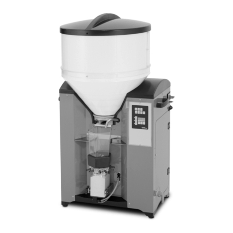
Oliver APF0038 User manual

APF0038/48 Stock Feeder
Owner’s Manual
Oliver Machinery M-4016 04/2008
Seattle, WA Copyright 2003
[email protected] www.olivermachinery.net

2
Warranty
Oliver makes every effort possible to assure that its equipment meets the highest possible standards of
quality and durability. All products sold by Oliver are warranted to the original customer to be free from
defects for a period of 2 (two) years on all parts, excluding electronics and motors, which are warranted
for 1 year. Oliver’s obligation under this warranty shall be exclusively limited to repairing or replacing (at
Oliver’s option) products which are determined by Oliver to be defective upon delivery F.O.B. (return
freight paid by customer) to Oliver, and on inspection by Oliver. This warranty does not apply to defects
due, directly or indirectly, to misuse, abuse, negligence, accidents, unauthorized repairs, alterations, lack
of maintenance, acts of nature, or items that would normally be consumed or require replacement due to
normal wear. In no event shall Oliver be liable for death, personal or property injury, or damages arising
from the use of its products.
Warning
Read this manual thoroughly before operating the machine. Oliver Machinery disclaims any liability for
machines that have been altered or abused. Oliver Machinery reserves the right to effect at any time,
without prior notice, those alterations to parts, fittings, and accessory equipment which they may deem
necessary for any reason whatsoever.
For More Information
Oliver Machinery is always adding new Industrial Woodworking products to the line. For complete, up-to-
date product information, check with your local Oliver Machinery distributor, or visit
www.olivermachinery.net

3
WARNING
Read this manual completely and observe all warning labels on the machine. Oliver Machinery has made
every attempt to provide a safe, reliable, easy-to-use piece of machinery. Safety, however, is ultimately
the responsibility of the individual machine operator. As with any piece of machinery, the operator must
exercise caution, patience, and common sense to safely run the machine. Before operating this product,
become familiar with the safety rules in the following sections.
1. If you are not properly trained in the use of a stock feeder do not use until the proper training has
been obtained.
2. Read, understand and follow the safety instructions found in this manual. Know the limitations and
hazards associated with this machine.
3. Electrical grounding: Make certain that the machine frame is electrically grounded and that a
ground lead is included in the incoming electrical service. In cases where a cord and plug are used,
make certain that the grounding plug connects to a suitable ground. Follow the grounding procedure
indicated in the National Electrical Code.
4. Eye safety: Wear an approved safety shield, goggles, or glasses to protect eyes. Common
eyeglasses are only impact-resistant, they are not safety glasses.
5. Personal protection: Before operating the machine, remove tie, rings, watch and other jewelry and
roll up sleeves above the elbows. Remove all loose outer clothing and confine long hair. Protective
type footwear should be used. Where the noise exceeds the level of exposure allowed in Section
1910.95 of the OSHA Regulations, use hearing protective devices. Do not wear gloves.
6. Guards: Keep the machine guards in place for every operation for which they can be used. If any
guards are removed for maintenance, DO NOT OPERATE the machine until the guards are
reinstalled.
7. Work area: Keep the floor around the machine clean and free of scrap material, saw dust, oil and
other liquids to minimize the danger of tripping or slipping. Be sure the table is free of all scrap,
foreign material and tools before starting to use the machine. Make certain the work area is well
lighted and that a proper exhaust system is used to minimize dust. Use anti-skid floor strips on the
floor area where the operator normally stands and mark off machine work area. Provide adequate
work space around the machine.
8. Material condition: Do not attempt to feed boards with loose knots or with nails or other foreign
material. Do not attempt to feed twisted, warped, bowed stock.
9. Operator position: Maintain a balanced stance and keep your body under control at all times.
10. Before starting: Before turning on machine, remove all extra equipment such as keys, wrenches,
scraps, and cleaning rags away from the machine.
11. Careless acts: Give the work you are doing your undivided attention. Looking around, carrying on a
conversation, and “horseplay” are careless acts that can result in serious injury.
12. Disconnect all power sources: Before performing any service, maintenance, adjustments or when
changing blades. A machine under repair should be RED TAGGED to show it should not be used
until the maintenance is complete.
13. Job completion: If the operator leaves the machine area for any reason, the feeder should be
turned "off" before their departure.

4
14. Replacement parts: Use only genuine Oliver Machinery factory authorized replacement parts and
accessories; otherwise the warranty and guarantee is null and void.
15. Misuse: Do not use this Oliver stock feeder for other than its intended use. If used for other
purposes, Oliver disclaims any real or implied warranty and holds itself harmless for any injury or
damage which may result from that use.
16. Drugs, alcohol and medication: Do not operate this machine while under the influence of drugs,
alcohol, or any medication.
17. Health hazards: Some dust created by power sanding, sawing, grinding, drilling and other
construction activities contains chemicals known to cause cancer, birth defects or other reproductive
harm. Some examples of these chemicals are:
Lead from lead-based paint.
Crystalline silica from bricks and cement and other masonry products.
Arsenic and chromium from chemically-treated lumber.
Your risk from these exposures varies, depending on how often you do this type of work. To reduce
your exposure to these chemicals, work in a well-ventilated area, and work with approved safety
equipment, such as those dust masks that are specifically designed to filter out microscopic particles.
Familiarize yourself with the following safety notices used in this manual:
CAUTION: (This means that if precautions are not heeded, it may result in minor or moderate injury
and/or possible machine damage)
WARNING: (This means that if precautions are not heeded, it could result in serious injury or possibly
even death).
ADDITIONAL SAFETY RULES FOR STOCK FEEDERS
1. Cutting tools MUST be rotating before feeding.
2. DO NOT overload the cutting tool by feeding too fast.
3. ALWAYS KEEP hands away from rotating parts.
4. PROVIDE support for long stock on out feed end of table.
5. STOP the feeder before stopping the cutting tool.
6. DISCONNECT power before making repairs or adjustment.

5
Table of Contents Page Number
Warranty ........................................................................................................................................................ 2
Warnings .................................................................................................................................................... 3-4
Table of Contents .......................................................................................................................................... 5
Specifications ................................................................................................................................................ 5
Contents of the Shipping Containers ............................................................................................................ 6
Machine Preparation and Setup ................................................................................................................... 7
Extension Wing Assembly ............................................................................................................................. 7
Handwheel Assembly .................................................................................................................................... 7
Rail Assembly ............................................................................................................................................... 8
Fence Assembly and Adjustment ................................................................................................................. 9
Adjusting the Scale Reader........................................................................................................................... 9
Calibrating the Digital Angle Readout ......................................................................................................... 10
Leveling Table Insert ................................................................................................................................... 11
Splitter and Blade Guard Assembly ............................................................................................................ 11
Miter Gauge ................................................................................................................................................ 12
Controls ....................................................................................................................................................... 12
Dust Collection ............................................................................................................................................ 12
Electrical Connections ................................................................................................................................. 13
Replacing the Blade .................................................................................................................................... 13
Maintenance ................................................................................................................................................ 14
Troubleshooting ..................................................................................................................................... 15-16
Specifications
Model Number ......................................................................................................................................... 4016
Blade Diameter (In) ..................................................................................................................................... 10
Arbor Diameter (In) ................................................................................................................................... 5/8"
Maximum Depth of Cut at 90 Degrees (In) .................................................................................................. 3"
Maximum Depth of Cut at 45 Degrees (In) ............................................................................................ 2-1/4"
Maximum Cut to the Right of Blade ........................................................................................................... 36”
Maximum Cut to the Left of Blade .............................................................................................................. 12”
Dust Port Diameter (In) ................................................................................................................................. 4
Table Dimensions w/Extensions (LxW) ...................................................................................... 27” x 45-1/4"
Table Height (In) ........................................................................................................................................ 36”
Blade Tilt ................................................................................................................................................... Left
Arbor Speed RPM .................................................................................................................................. 3,450
Gross Weight (with 36” rails and fence) .................................................................................................... 639

- 6 -
APF0038-48
E
D
F
TABLE OF CONTENTS
IMPORTANT SAFETY RULES -
-------------------------------- ------ 3
ADDITIONAL SAFETY RULES
FOR POWERFEEDER --------- 4
LOCATE MOUNTING AND
BORING POSITION ------------ 4
ASSEMBLING -------------------- 5
OPERATION CONTROLS ---- 7
POWER CONNECTION AND
GROUNDING --------------------- 9
FEED RATE SETTING ------- 10
ROLLER REPLACEMENT -- 12
LUBRICATION AND
MAINTENANCE ---------------- 13
USING FEEDER ON
MACHINES ---------------------- 14
NOTES & EXPLODED VIEWS
–-----------------------------

- 7 -
APF0038-48
E
D
F
LOCATE MOUNTING
AND BORING
POSITION
A) LOCATE MOUNTING
POSITION
1. Elevation and extension of
Universal Stands, (SEE FIG. 1,
2 & 3, HP shown on motor
cover of your feeder.)
2. Refer to Page 13 FIG. 27, 28,
29 for assistance when
mounting the feeder to a
shaper, table saw or jointer.
3. For small machine table, an
extension bracket (not
provided) is recommended.
(SEE FIG. 4.)
B) LOCATE BORING POSITION
For your boring convenience and
accuracy, A SCALE 1:1 SELF-
ADHESIVE DRILLING TEMPLATE
is provided and enclosed in the
package. (FIG. 5)
1. Remove MOUNTING BASE
from packaging. Use it to verify
the correct boring position on
the drilling template.
2. Prepare 4 sets of bolts &
spring washers (not provided).
SIZE OF BOLT
Light Duty (1/4HP) - M10
Light-heavy Duty & - M12
Heavy Duty (≧1/2 HP)
LENGTH OF BOLT ≧
Mounting Base (thickness) +
Tabletop (thickness).
3. Avoid table ribs and support
underneath the table.

- 8 -
APF0038-48
E
D
F
4. Use SELF-ADHESIVE
DRILLING TEMPLATE. Tape it
to desire position. Mark it with center
punch.
5. BORE & TAP.
ASSEMBLING (FIG.
6, 7, 8)
WARNING: Get help!
Feeder is heavy. Do not try to
do it on your own.
ZUSAMMENSETZUNG
(FIG. 6, 7, 8)
WARNUNG: Holen Sie Hilfe!
Die Zuführungsvorrichtung ist sehr
schwer. Versuchen Sie nicht allein die
Zuführungsvorrichtung zu installieren.
MONTAGE
(FIG. 6, 7, 8)
ATTENTION: Demandez de
l’aide! L'alimentateur est lourd. Ne
le faites pas seul.
FIG. 4
FIG. 5
Light Duty
Light-heavy Duty
Heavy Duty
FIG. 1
Light Duty =
1/4 HP models
403-201mm
(15”-8”)
429-308mm
(16”-12”)
FIG. 2
Light-Heavy Duty =
1/2 HP models
624-246mm
(24”-9”)
560-482mm
(22”-16”)
FIG. 3
Heavy Duty =
1 HP models
630-208mm
(25”-8”)
842-664mm
(33”-26”)

- 9 -
APF0038-48
E
D
F
A) Fasten BASE (1) to table.
B) Insert “STAND” to BASE (1).
Assemble HANDLE (11).
(SEE 6-1).
C) Insert OVER ARM (2) into
ELEVATING BRACKET (3). Turn
WHEEL (4) a few turns.
Tighten LEVER (5).
D) Reposition motor. Loosen 4
SCREWS. (SEE FIG 7).
E) Assemble CONTROL JOINT
(6-2) onto motor neck. (SEE
FIG. 6). MAKE SURE:
Tighten SCREW (6) & LEVER
(7) and keep gap on both side
EQUALLY SPACED. So, once
LEVER is loosen, feeder can
swivel without having to loosen
the SCREW (6). (SEE 6-2).
MOTOR CLAMP OPENING is
PARALLEL to HOUSING.
(SEE 6-2).
A) Stellen Sie die BASIS (1) fest an den Tisch.
B) Stecken Sie den “STÄNDER” auf die
BASIS (1). Setzen Sie den GRIFF (11)
zusammen. (SIEHT FIG. 6-1).
C) Stecken Sie den Gegenhalter (2) in den
ERHÖHTEN HLTER (3) hinein. Drehen das
Rad (4) ein paar male. Ziehen Sie den
HEBEL fest (5).
D) Neu Positionieren Sie das MOTOR.
Schrauben Sie 4 SCHRAUBEN ab.
(SIEHT FIG. 7).
E) Setzen die KONTROLLE-FUGE (6-2) mit
dem Halz des Motors zusammen. (SIEHT
FIG. 6). SORGEN SIE DAFÜR:
Schrauben die SCHRAUBE (6) & den
HEBEL (7) fest und halten die Distanz bei
beider Seiten IN GLEICHER ENTFERNUNG.
So daß wenn der Hebel aufgelockert ist,
wird die Zuführungsvorrichtung schwingen
ohne die Schrauben abschrauben zu
müssen (6). (SIEHT 6-2).
MOTOR-KLAMMER ÖFFNUNG steht
PARALLEL zum GEHÄUSE. (SIEHT 6-2).
A) Fixez la base (1) à la table.
B) Insérez la colonne verticale dans la
base (1). Assemblez la poignée (1)
(VOIR FIG.6-1)
C) Insérez le bras ajustable (2) dans
l'équerre d'élévation (3). Tournez la
roue (4) pour quelques tours. Serrez
la poignée (5).
D) Repositionnez le moteur. Desserrez 4
vis. (FIG. 7).
E) Fixez la bride de moteur (FIG. 6-2) sur
le collet du moteur. (FIG. 6).
ASSUREZ-VOUS DE:
Resserrez les vis (6) et la poignée
(7) de façon égale. Ainsi lorsque la
poignée est desserrée, l'alimentateur
peut pivoter sans avoir à desserrer
les vis (6) (FIG. 6-2).
La bride de moteur est parallèle au
châssis. (FIG. 6-2)
FIG. 6
5
3
2
12
11
9
10
4
8
13
1
6
7
6-1
6-2
HOUSING
6
7
8
6-3
90°
8
HOUSING
6-4
10
9
FIG. 7
FIG. 8
12

- 10 -
APF0038-48
E
D
F
Loosen LEVER (8) & adjust
CONTROL JOINT UPRIGHT
90° to HOUSING. Tighten
LEVER (8). (SEE 6-3).
F) Assemble FEEDER to OVER
ARM (2). Tighten SCREWS (9).
MAKE SURE:
Center of LEVER (10) is IN
LINE with center of OVER-
ARM (2). (SEE 6-4).
G) Move FEEDER to desired
position by loosen LEVER (10).
Adjust height (11 & 12) and
extension (4 & 5) accordingly.
H) Tighten all LEVERS.
IMPORTANT:
There is certain “PLAY” between
ELEVATING KEY & BRACKET
GROOVE. To assure “STURDY
FEEDING,” pull FEEDER against
your IN-FEED direction, then
tighten LEVER (12). (SEE FIG. 8)
Do it on “EVERY ADJUSTMENT.”
Locken den HEBEL (8) auf & stellen die
KONTROLLE-FGE SENKRECHT 90°
zum GEHÄUSE. Stellen den HEBEL fest
(8). (SIEHT FIG. 6-3).
F) Setzen Sie die ZUFÜHRUNGSVORRICHTUNG
zum GEGENHALTER zusammen (2).
Schrauben die SCHRAUBEN (9) fest.
SORGEN SIE DAFÜR:
Die Mitte des HEBELS (10) bleibt
IN DER LINIE von Mitte des
GEGENHALTERS (2). (SIEHT
FIG. 6-4).
G) Locken Sie den HEBEL (10) auf, damit Sie
die ZUFÜHRUNGSVORRICHTUNG auf
beliebige Position bewegen können. Je
nach dem Bedarf stellen Sie die Höhe (11 &
12) und die Verlängerung (4 & 5) um.
H) Stellen alle HEBEL fest.
WICHTIG: Es gibt mehrere
“Spiele” zwischen den erhöhten Schlüssel
und den Halterrillen. Um “FESTE ZUFUHR”
sicherzustellen, ziehen Sie den
ZUFÜHRUNGSVORRICHTUNG gegen die
EINFUHRSRICHTUNG, dann ziehen Sie den
HEBEL fest (12). (Sieht FIG. 8). Wiederholen
Sie diesen Schritt bei “JEDER
EINSTELLUNG”.
Desserrez la poignée (8), ajustez
la bride de moteur
perpendiculairement au châssis,
serrez la poignée (8) (Voir FIG. 6-
3).
F) Fixez l'alimentateur au bras ajustable
(2) serrez les vis (9) ASSUREZ-VOUS
DE:
D'aligner le centre du bras ajustable
(2) avec le centre de la poignée (10)
(Voir FIG. 6-4).
G) Positionnez l'alimentateur à la position
désirée en desserrant la poignée (10).
Ajustez la hauteur (11 et 12) et le
déplacement latéral ( 4 et 5 ) selon la
position choisie.
H) Serrez toutes les poignées.
IMPORTANT:
Il y a un jeu entre la clé d'élévation et la
vis d'élévation. Pour assurer une
alimentation ferme, tirez l'alimentateur
vers la direction d'alimentation puis serrez
la poignée (12). (FIG. 8) Le faire après
chaque ajustement.
OPERATION
CONTROLS
(FIG. 9 & 10)
WARNING: Disconnect
feeder from power source.
BETRIEBSKONTROLLE
(FIG. 9 & 10)
WARNUNG: Schalten Sie den
Anschluß von der Zuführsvorrichtung aus.
MANŒUVRES DE
FONCTIONNEMENT
(FIG. 9 & 10)
ATTENTION: Débranchez
l’alimentation électrique.
FIG. 9
13
12
11
5
4
2
10
FIG. 10
9
8
16
15
7
14

- 11 -
APF0038-48
E
D
F
A) STAND: (FIG. 9)
OVER ARM (2) rotation.
Loosen LEVER (13).
OVER ARM (2) elevation.
Loosen LEVER (12) &
rotate TOP WHEEL (11).
OVER ARM (2) extension.
Loosen LEVER (5) &
rotate SIDE WHEEL (4).
B) CONTROL JOINT: (FIG. 10)
ARM BRACKET (14)
Loosen SCREWS (9).
ANGLE JOINT (15)
Loosen LEVER (10).
MOTOR CLAMP (16)
Loosen LEVER (8).
MOTOR CLAMP (16)
Loosen LEVER (7).
C) ROLLER LEVELING: Lower
Feeder to table. (SEE FIG. 9).
C)-1: Loosen LEVER (8),
Adjust ANGEL JOINT (15).
(FIG. 10)
C)-2: Loosen SCREWS (9),
Adjust ARM BRACKET (14)
(FIG. 10)
Alignment “SLIGHTLY OFF”
is acceptable. (Offset by
independent suspension.)
D) SIDE FEEDING: (SEE FIG. 9,
10 & 11)
Loosen LEVER (13), swing
FEEDER off the table.
Loosen LEVER (8), turn
FEEDER 90° to floor with
ROLLERS facing you. Tighten
LEVER (8).
Loosen LEVER (7), turn
FEEDER 90° with SWITCH
BOX facing up. Tighten
LEVER (7).
Loosen LEVER (10), push
FEEDER to desired position.
Tighten LEVER (10 & 13).
WARNING: Tighten all
Levers after each adjustment.
A) STÄNDER: (FIG. 9)
GEGENHALTER (2) Drehung :
Locken Sie den Hebel auf. (13).
GEGENHALTER (2) Verlängerung:
Locken Sie den Hebel auf (12) &
drehen Sie das SEITENRAD (11).
GEGENHALTER (2) Erhöhung:
Locken Sie den HEBEL auf (5) &
Drehen Sie DAS OBERE RAD (4).
B) KONTROLLE-FUGE: (FIG. 10)
ARM-HALTER (14)
Schrauben die SCHRAUBEN ab
(9).
WINKEL-FUGE (15)
Locken den HEBEL auf (10).
MOTOR-KLAMMER (16)
Locken den HEBEL auf (8).
MOTOR-KLAMMER (16)
Locken den HEBEL auf (7).
C) ROLLEN AUSRICHTUNG: Lassen die
Zuführungsvorrichtung runter auf den
Tisch, (SIEHT FIG. 9).
C)-1: Locken den HEBEL auf (8),
stellen WINKEL-FUGE um (15). (FIG.
10)
C)-2: Schrauben die SCHRAUBEN ab
(9), stellen ARM-HALTER (14). (FIG. 10)
Ausrichtung “EIN WENIG AUF” ist
akzeptabel. (Ausgleich durch
eigenständige Verschiebung.)
D) SEITEZUFUHR: (SIEHT FIG. 9, 10 & 11.)
Locken den HEBEL auf (13),
schwingen die
ZUFÜHRUNGSVORRICHTUNG von
dem Tisch.
Locken den HEBEL auf (8), drehen
die ZUFÜHRUNGSVORRICHTUNG
90° zum Boden und die ROLLE zur
Ihnen. Stellen den HEBEL fest
(8).
Locken den HEBEL auf (7), drehen
die ZUFÜHRUNGSVORRICHTUNG
90° und der SCHALTERKASTEN nach
Oben. Stellen den HEBEL fest
(7).
Locken den HEBEL (10), drüken die
ZUFÜHRUNGSVORRICHTUNG auf
beliebige Stelle. Stellen den
HEBEL fest (10 & 13).
WARNUNG: Stellen alle HEBEL fest
nach jeder Einstellung.
A) COLONNE DE CONTROLE: (FIG. 9)
BRAS (2) rotation.
Détachez LEVIER (13).
BRAS (2) élévation.
Détachez LEVIER (12) &
tournez ROUE EN TOP (11).
BRAS (2) extension.
Détachez LEVIER (5) &
tournez ROUE DE COTE (4).
B) BRIDE DE MOTEUR: (FIG. 10)
BRAS CROCHET (14)
Détachez VIS (9).
ANGLE JOINT (15)
Détachez LEVIER (10).
PRESSEUR DU MOTEUR (16)
Détachez LEVIER (8).
PRESSEUR DU MOTEUR (16)
Détachez LEVIER (7).
C) AJUSTEMENT DES ROULEAUX:
Descendez l’alimentateur sur la table
(VOIR FIG. 9).
C)-1: Desserrez la poignée (8).
Ajustez le cône pivotant (15).
(VOIR FIG. 10).
C)-2: Desserrez les VIS (9), Ajustez
le BRAS DU CONE (14). (FIG. 10).
Un léger jeu dans l'alignement des
roues est acceptable. (Décalé par
une suspension independante.)
D) ALIMENTATION LATERALE (VOIR
FIG. 9, 10 et 11 )
Desserrez la poignée (13), Pivotez
l'alimentateur hors de la table.
Desserrez la poignée (8), Tournez
l'alimentateur à un angle de 90° avec
le sol, rouleaux face à vous.
Resserrez la poignée (8).
Desserrez la poignée (7), Tournez
l’alimentateur de 90° avec la boite de
l'interrupteur vers le haut.
Resserrez la poignée (7).
Desserrez la poignée (10),
Déplacez l'alimentateur vers la
position voulue. Resserrez les
poignées (10 et 13).
ATTENTION: Serrez toutes les
poignées après chaque ajustement.
FIG. 11
C) - 1
C) - 2

- 12 -
APF0038-48
E
D
F
POWER CONNECTION
AND GROUNDING
(FIG. 12, 13 & 14)
WARNING: Make sure
electric currency matches the
motor specification (see
motor cover.)
WARNING: Make sure
switch is on the “OFF”
position.
A) CE REQUIRED COUNTRY:
Feeder is a supplemental
tool, which works in conjunction
with your shaper, table saw,
jointer, … etc. It’s
recommended to be used with
a machine that is wired in
compliance with your national
or local electrical regulation.
It must be connected to your
machine through a specially
designed current taps that
ensures your machine’s switch
and emergency stop having
controls of your feeder’s power
source. In addition, the current
tap must provides an overload
and under voltage protection
systems.
Rated Current List
Electrical connection is
reserved for certified electrician
only.
B) OTHER’S COUNTRY:
A separate electrical outlet
should be used for your feeder.
The circuit should not be less
than # 12. Wire properly
installed and grounded in
accordance with your local
codes and ordinances,
protected with a 15 Amp time
lag fuse or circuit breaker.
If an extension cord is used,
≦ 30M (100Ft), use #12 Wire;
≧ 46M (150Ft), use #10 Wire.
Ensure all line connections
make good contact. Low
voltage running will damage the
motor.
Properly ground the motor to
reduce the risk of electrical
shock.
The motor is equipped with a
grounding conductor (green
wire with or without yellow
stripes.)
If unsure, consult with a
qualified electrician.
Model 32 308/408 34/44/38/48/04/54/C3/MX 30/40
Current 1.5A 2A 2.5A 3A

- 13 -
APF0038-48
E
D
F
FEED RATE SETTING
WARNING: Disconnect
feeder from power source.
A) Choosing the right feed rate is
important to achieve efficiency
and quality. It is closely related to
the speed of your machine, the
sharpness of cutter, the
hardness and the thickness of
the material to be removed.
Listening to the sound of your
cutting tool, look (exam) closely
at your sample pieces.
(Feed rate chart below is for
reference only.)
B) Setting the available feed rate is
a combination of MOTOR
SPEEDS (FIG. 15) & GEAR
SETTINGS. (Ref. FIG. 16-1, 16-
2, 16-3.)
Model 32:
(A) + GEAR SETTINGS.
Model 308/408 (3 Phase):
(B) + GEAR SETTINGS.
Model 308/408 (1 Phase):
(C) + GEAR SETTINGS.
Model 34/44/04/54/C3:
(B) + GEAR SETTINGS.
FIG. 16-1.
Model 38/48:
(C) + (D) + GEAR
SETTINGS. FIG. 16-2.
Model 30/40 Variable-Speed:
(C) + (E).
Model MX:
(B) + GEAR SETTINGS.
FIG. 16-3.
VORSCHUB EINSTELLUNG
WARNUNG: Schalten Sie den
Stromanschluß der
Zuführungsvorrichtung aus.
A) Die richtige Vorschubsgeschwindigkeit zu
wählen ist sehr wichitg für beste Effizienz
und Qualität. Die Geschwindigkeit ihrer
Maschine, die Schärfe des Schneiders und
die Härte und Dicke der Materials sind eng
miteinder verbunden. Hören Sie vorsichtig
auf das Geräusch ihrer Schneidmaschine.
Sehen Sie vorsichtig die Musterstücke
nach.
(Die Vorschubsgeschwindigkeitstabelle unten
ist nur als Referenz.)
B) Die Vorschubsgeschwindigkeit besteht aus
Kombination der GESCHWINDIGKEIT DES
MOTORS (FIG. 15) & GANG
EINSTELLUNG. (Ref. FIG. 16-1, 16-2, 16-
3.)
Model 32:
(A) +GANG EINSTELLUNG.
Model 308/408 (3 Phase):
(B) +GANG EINSTELLUNG.
Model 308/408 (1 Phase):
(C) +GANG EINSTELLUNG.
Model 34/44/04/54/C3:
(B) +GANG EINSTELLUNG.
FIG. 16-1.
Model 38/48:
(C) + (D) + GANG
EINSTELLUNG. FIG. 16-2.
Model 30/40 Variable-Speed:
(C) + (E).
Model MX:
(B) +GANG EINSTELLUNG.
FIG. 16-3.
RÉGLAGE DE LA VITESSE
D'ENTRAÎNEMENT
ATTENTION: Débranchez
l’alimentation.
A) Le bon choix de la vitesse est
primordial pour réussir un travail
efficace et de qualité. Le résultat est
étroitement relié à la vitesse de la
machine, à l'affûtage des couteaux, à
la dureté du bois ainsi qu'a l'épaisseur
de la pièce à travailler. Soyez attentifs
au son des outils de coupe, examinez
vos échantillons de travail.
(Le tableau de vitesse d'entraînement ci-
dessus est donné uniquement comme
référence.)
B) L'ajustement de la vitesse
d'alimentation disponible se fait par
des combinaisons de vitesse de
moteur et de position d'engrenage.
(Ref. FIG. 15, 16-1, 16-2, 16-3.)
Modèle 32:
(A) + POSITION
D'ENGRENAGE.
Modèle 308/408 (3 Phase):
(B) +POSITION D'ENGRENAGE.
Modèle 308/408 (1 Phase):
(C) +POSITION D'ENGRENAGE.
Modèle 34/44/04/54/C3:
(B) +POSITION
D'ENGRENAGE. FIG. 16-1.
Modèle 38/48:
(C) + (D) +POSITION
D'ENGRENAGE. FIG. 16-2.
Modèle 30/40 Variable-Speed:
(C) + (E).
Modèle MX:
(B) +POSITION
D'ENGRENAGE. FIG. 16-3.
FIG
. 12
308/408/34/38/44/48/04/54/C3/MX
30/40
FIG.
14
32
FIG
. 13
Feeding
speed
Thickness
of work piece
9 15 23 9 15 23 15 23 23
8 12 15 8 15 15 12 15 15
5 9 12 6 12 12 8 12 12
3 5 6 5 6 8 6 8 9
25 mm
6 mm
10 mm
20 mm
Cutters
6000 R.P.M.
8000 R.P.M.
10000 R.P.M.
Spindle Speed

- 14 -
APF0038-48
E
D
F
NOTE:
GEAR-SPEED-CONTROL LEVER
(D) will not operate unless the
motor is running position.
NOTE:
The “ACCU-RATE KNOB" (E)
cannot be rotated when motor is on
“OFF” position.
NOTE:
If your GEARS come with a HUB,
make sure it FACES the SHAFT
avoiding damages to the chain
drive. (FIG. 17)
NOTE:
To enlarge your available speed
range on feeder, extra set of gear is
available at your dealer. [XG1634
for Light-duties (Model: 32 → 4 + 2
= 6) & XG2144 for Heavy-duties
(Models: 34/44 → 4 + 4 = 8)]
A) A gear arrangement and feed
rate chart is attached to the
INSIDE of GEARBOX- COVER.
(Ref. FIG. 16-1, 16-2 & 16-3.)
B) To remove GEARBOX-COVER,
remove two KNOBS. (FIG. 18)
C) To remove & rearrange GEARS,
remove HEX-NUTS. (FIG. 19)
ANMERKUNG:
GANGE-GESCHWINDIGKEIT-KONTROLLE
HEBEL (D) kommt nicht in Betrieb außer das
Motor in Betrieb ist.
ANMERKUNG:
Der “ACCU-RATE KNAUF" (E) kann nicht
umdrehen wenn das Motor auf “AUS” gestellt
ist.
ANMERKUNG:
Wenn ihre GÄNGE mit einer NABE versehen,
sorgen Sie dafür, daß die Nabe ZU dem
SCHACHT stellen, um die Schade des
Kettenantrieb zu vermeiden. (FIG. 17)
ANMERKUNG:
Um die Geschwindigkeitsumfang der
Zuführungsvorrichtung zu vergrößern, können
Sie ein zusätzliches Gangset beim ihrem
Händler kaufen. [XG-1634 for Leichte
Kapazität (Model: 32 → 4 + 2 = 6) & XG2144
für hohe Kapazität (Models: 34/44 → 4 + 4 =
8)]
C) Eine Tabelle für Ganginstallation und
Vorschubsgeschwindigkeit befindet sich
auf der INNENSEITE des
GANGKASTENDECKELS. (Ref. FIG.
16-1, 16-2 & 16-3.)
D) Wenn Sie den GANGKASTENDECKEL
entfernen möchten, müssen Sie zuerst die
zwei KNAUFE entfernen. (FIG. 18)
E) Wenn Sie die GÄNGE entfernen und
umstellen möchten, müssen Sie die
sechseckige Schrauben entfernen.
(FIG. 19)
NOTE:
(D) Le levier de contrôle de la vitesse
d'engrenage ne fonctionne pas tant que le
moteur n'est pas en fonction.
NOTE:
Le “BOUTON ACCU-VITESSE (E) " Ne
peut être tourné quand le moteur est en
position.
NOTE:
Si votre engrenage est muni d'un moyeu,
assurez-vous qu'il soit face à l'arbre pour
éviter des dommages à la chaîne motrice.
(FIG. 17)
NOTE:
Pour doubler les vitesses disponibles sur
votre modèle, un jeu supplémentaire de
vitesse est disponible chez votre
marchand. [XG1634 Jeu Light-duties
(Modèle: 32 → 4+2=6) & XG2144 Jeu
Heavy-duties (Modèle: 34/44 → 4+4=8)]
C) Un tableau sur les positions
d'engrenage et les vitesses
d'entraînement est disponible dans le
couvercle de la boîte d'engrenage.
(Ref. FIG. 16-1, 16-2 & 16-3.)
D) Pour enlever le couvercle, retirez les
deux boutons. (FIG. 18)
E) Pour retirer et ajuster les engrenages,
dévissez les écrous Hex. (FIG. 19)
FIG. 18
FIG. 16-3
FIG. 16-1
FIG. 16-2
FIG. 15
(A)
(B)
(C)
(D)
(E)
Switches
Gear Hub
FIG. 17
FIG. 19

- 15 -
APF0038-48
E
D
F
ROLLER
REPLACEMENT
(FIG. 20)
WARNING: Disconnect
feeder from power source.
Remove SCREWS and replace
ROLLER(s). Replace SCREWS
with each roller replacement.
NOTE:
“ROTATE” roller positions
periodically will prolong the usage
of rollers.
ROLLER TIRE
REPLACEMENT
(FIG. 21, 22 & 23)
(Heavy-duty
models, 3 or 4
Rollers)
1. Remove 4 SCREWS. (FIG. 21)
2. Force ROLLER-WHEELS
out. POUND roller on tabletop.
(FIG. 22)
3. Pre-assemble FRIENDLY
ROLLER with new TIRE (FIG.
23), with MALE-WHEEL (marked
M) inside and FEMALE-WHEEL
(marked F) outside. Lined up
UNTHREADED HOLES of both
WHEELS.
4. Slip 2 x 40mm SCREWS all the
way through UNTHREADED
HOLES. (FIG. 23)
5. Tighten new ROLLERS to
housing.
6. Tighten 2 x 20mm SCREWS
through remaining holes.
7. Secure all SCREWS.
8. Disregard “SLIGHT
WOBBLING” of the new TIRES.
— It will adjust itself once in use.
9. Check all SCREWS and RE-
TIGHTEN them after first run.
ROLLE AUSWECHSELUNG
(FIG. 20)
WARNUNG: Schalten Sie den
Stromanschluß von der
Zuführungsvorrichtung aus.
Entfernen SCHRAUBEN und wechseln die
ROLLEN. Wechseln SCHRAUBEN beim
jeden Rolleauswechselung.
ANMERKUNG:
“DREHEN” die Positionen der Rollen
regelmäßig kann die Nutzungszeit der Rollen
verlängern.
ROLLERAD
AUSWECHSELUNG
(FIG. 21, 22 & 23)
(Hohe Kapazität Model,
3 oder 4 Rollen)
1. Entfernen Sie 4 SCHRAUBEN. (FIG. 21)
2. Zwingen die ROLLE-RÄDE raus.
SCHLAGEN die Rollen auf den Tisch.
(FIG. 22)
3. Setzen Sie leicht die ROLLEN mit neuem
RAD zusammen (FIG. 23), innen mit
MÄNNLICHEM RAD (markiert M) und
außen mit WEIBLICHEM RAD (markiert F).
Stellen die NICHT GEWINDELTE
LÖCHER der zwei RÄDER in einer Linie.
4. Schlüpfen 2 x 40mm SCHRAUBEN
durch die NICHT GEWINDELTE
LÖCHER. (FIG. 23)
5. Ziehen Sie die neue ROLLEN an das
Gehäuse fest.
6. Schrauben 2 x 20mm SCHRAUBEN fest
durch die andere Löcher.
7. Schrauben alle SCHRAUBEN fest.
8. Beachten Sie nicht die “EIN WENIG
WACKELNDE” neuen RÄDE. — Wenn
die Räder in Betrieb kommen, werden sie
selbst regulieren.
9. Überprüfen Sie alle SCHRAUBEN und
SCHRAUBEN SIE NEU FEST nach dem
ersten Betrieb.
REMPLACEMENT DES
ROULEAUX (FIG. 20)
ATTENTION: Débranchez
l'alimentation.
Retirez les vis et remplacez le (s) rouleau
(x). Remplacez les vis après chaque
changement.
NOTE:
Faire une “Rotation" régulière
prolongera la durée des rouleaux.
REMPLACEMENT DES
PNEUS DES ROULEAUX
(FIG. 21, 22 & 23)
(Modèles lourds,
3 ou 4 Rouleaux)
1. Enlevez les 4 VIS. (FIG. 21)
2. Retirez le rouleau, pressez
légèrement le rouleau sur le dessus de
la table. (FIG. 22)
3. Pré-assemblez le rouleau avec le
nouveau pneu (FIG. 23), avec la roue
mâle (IDENTIFIE - M) à l'intérieur et la
roue femelle (IDENTIFIE - F) à
l'extérieur. Alignez les trous ( sans
filets) des deux roues.
4. Insérez 2 vis (40mm) à travers les
trous (sans filets) (FIG. 23)
5. Fixez les nouveaux rouleaux au
châssis.
6. Insérez 2 vis (20mm) à travers les
trous disponibles.
7. Serrez toutes les vis.
8. Ne vous préoccupez pas du léger
débalancement des nouveaux pneus,
l'ajustement se fera automatiquement
lors de l'utilisation.
9. Contrôlez et re-serrez toutes les VIS
aprés chaque utilisation
M F
FIG. 23
FIG. 21
FIG. 22
1
2

- 16 -
APF0038-48
E
D
F
LUBRICATION & MAINTENANCE
(FIG. 24 & 25)
WARNING: Disconnect feeder from power
source.
A) ROLLERS:
Grease every 200 hrs (30 days) through fittings, using
grease gun. Recommended Grease: # 2 GREASE. (Shell –
Alvania Grease R2 or equivalents.)
B) GEARS & CHAINS:
Lubricate periodically with grease.
Recommended Grease: # 2 GREASE. (Shell – Alvania
Grease R2 or equivalents.)
C) GEAR BOX:
Change oil first 200 hrs (30 days.)
Change oil every 1000 hrs (6 months.)
Recommended Gear Oil: MOBIL Mobilgear 630,
Shell/Omala 150 BP, Energol GR-XP 150, or equivalents.
Above recommendation is based on 8 hours/day.
D) OIL CHANGE: (SEE FIG. 6)
Loosen LEVER (13) and swing FEEDER off the table.
Loosen LEVER (8) on ANGLE-JOINT. Turn FEEDER
upside down, loosen OIL-CAPE, and allow time to drain.
E) MODEL & OIL LEVEL:
32 100CC (29mm, 1-1/8")
308 130CC (42mm, 1-5/8")
408 150CC (42mm, 1-5/8")
34/44 380CC (38mm, 1-1/2")
38/48 300CC (38mm, 1-1/2")
30/40 140CC (35mm, 1-3/8")
04/54 350CC (42mm, 1-5/8")
MX 200CC (38mm, 1-1/2")
F) MAINTENANCE
Remove working-waste (saw dust, shavings, etc)
from the feeder by air gun after each use.
FIG. 24
FIG. 25

- 17 -
APF0038-48
E
D
F

- 18 -
APF0038-48
E
D
F
Applications
3-Roller model shown with the
4th roller (model) in dot line.
A) ON A SHAPER: FIG. 27
Roller Position
-VS- Cutter FIG. 27
Feeder Position
-VS- Fence FIG. 30-
1
Feeder Pressure
-VS- Feeding Stock FIG. 31-
1
B) ON A TABLE SAW: FIG. 28
Roller Position
-VS- Saw Blade FIG. 28
Feeder Position
-VS- Fence FIG. 30-2
Feeder Pressure
-VS- Feeding Stock FIG. 31-1
C) ON A JOINTER: FIG. 29
Roller Position
-VS- Cutter Blade FIG. 29
Feeder Position
-VS- Fence FIG. 30-1
Feeder Pressure
-VS- Feeding Stock FIG. 31-2
11
A
B
FIG. 30
B–A ≒ 5mm (1/4”) : 30-1
B–A≒ 2mm (1/16”) : 30-2
FIG. 27
FIG. 29
5mm
(1/4”)
Mounting
Position
FIG. 28
31-1: 3 ~ 4 mm (≒ 1/8”)
31-2: As light as possible
So leicht wie möglich
Aussi légère que possible
FIG. 31

- 19 -
APF0038-48
E
D
F

20
E
D
F
This manual suits for next models
1
Table of contents