Edge Technologies Patriot Series User manual

Patriot 338 & 551
OPERATIONS MANUAL

PATRIOT SERIES 338&551
HYDRODYNAMIC AUTOMATIC BAR FEEDER
PATRIOT
MANUAL FOR USE AND MAINTENANCE
REV. 5 DATE:2015/10/01 COD:BPA102032
S/H

Table of contents Patriot Series
I
1. General Information
Section Page
1.1 Contents of the Manual -------------------------------------------------------------------------------------- 1
1.2 Machine Data Plate ------------------------------------------------------------------------------------------- 2
1.3 Technical Support --------------------------------------------------------------------------------------------- 2
2. Technical Information
2.1 Description of the Machine --------------------------------------------------------------------------------- 3
2.2 Machine Footprint --------------------------------------------------------------------------------------------- 4
2.3 Capacities and Requirements ----------------------------------------------------------------------------- 4
2.4 Compressed Air Supply ------------------------------------------------------------------------------------- 5
2.5 Electrical Supply ---------------------------------------------------------------------------------------------- 6
2.6 Guide Channel Specifications ----------------------------------------------------------------------------- 6
2.7.1 Bar Stock Straightness Requirements ---------------------------------------------------------------- 7
2.7.2 Procedure for Checking Bar Stock Straightness -------------------------------------------------- 7
2.7.3 Bar Stock Preparation ------------------------------------------------------------------------------------ 8
2.7.4 RPM Limiting Factors ------------------------------------------------------------------------------------- 8
3. Transportation and Handling
3.1 Packaging of the Bar Feeder ------------------------------------------------------------------------------ 9
3.2 Transporting the Bar Feeder ------------------------------------------------------------------------------- 9
3.3 Installation Area --------------------------------------------------------------------------------------------- 10
4. Installation
4.1 Lathe Preparation ------------------------------------------------------------------------------------------- 11
4.2 Distance From Lathe -------------------------------------------------------------------------------------- 11
4.3 Height Adjustment ------------------------------------------------------------------------------------------ 12

Table of contents Patriot Series
II
4.4 Leveling -------------------------------------------------------------------------------------------------------- 12
4.5 Alignment ------------------------------------------------------------------------------------------------------ 13
4.5.1 Preparing the Bar Feeder ------------------------------------------------------------------------------- 13
4.5.2 Aligning the Center Lines ------------------------------------------------------------------------------- 14
4.5.3 Anchoring the Bar Feeder ------------------------------------------------------------------------------ 15
4.6 Installation of Accessories -- ----------------------------------------------------------------------------- 16
4.6.1 Moveable Anti-Vibration Device (MAVD) ----------------------------------------------------------- 16
4.6.2 Fixed Front Nose ----------------------------------------------------------------------------------------- 17
4.6.3 Telescoping Front Nose --------------------------------------------------------------------------------- 17
4.6.4 Synchronization Device --------------------------------------------------------------------------------- 18
4.7 Oil for Guide Channel -------------------------------------------------------------------------------------- 19
5. Adjustments and Settings
5.1 Structure of the Bar Feeder ------------------------------------------------------------------------------- 20
5.2 Adjustment of the Loading Device ---------------------------------------------------------------------- 21
5.3 Chain Adjustment and Lubrication ---------------------------------------------------------------------- 22
5.4 Moveable Anti-Vibration Device Adjustment --------------------------------------------------------- 23
6. Control Operations and Descriptions
6.1 Sequence to Manually Change Bars ------------------------------------------------------------------- 24
6.2 Start Up -------------------------------------------------------------------------------------------------------- 25
6.3 Clearing an Alarm ------------------------------------------------------------------------------------------- 25
6.4 Resetting the Zero Position ------------------------------------------------------------------------------- 26
6.5 Description of the Manual Screen ----------------------------------------------------------------------- 27
6.6 Description of the Automatic Screen ------------------------------------------------------------------- 28
6.7 Loading With the Bar On and Bar Off Buttons ------------------------------------------------------- 29

Table of contents Patriot Series
III
6.8 Entering a New Program ---------------------------------------------------------------------------------- 30
6.9 Selecting and Editing an Existing Program ----------------------------------------------------------- 33
7. General Maintenance
7.1 Periodic Maintenance -------------------------------------------------------------------------------------- 34
7.2 Rotating Tip and Collet ------------------------------------------------------------------------------------ 34
7.3 Air Filter/Regulator/Lubrication Unit -------------------------------------------------------------------- 34
Parameters
8. User Parameters ---------------------------------------------------------------------------------------------- 35
9. Factory Parameters ------------------------------------------------------------------------------------------ 47
10. Service Technician Parameters ------------------------------------------------------------------------- 58
Alarms
11. Error Alarms -------------------------------------------------------------------------------------------------- 62
Electrical Schematic
12. Machine Electrical Drawings ----------------------------------------------------------------------------------
Parts
13. Parts List -----------------------------------------------------------------------------------------------------------

1. General Information Patriot Series
1
1. General Information
Please read and understand the Manual before operating the bar feeder
1.1 Contents of the Manual
The bar feeder manufacturer has provided this manual as an integral part of the machine.
Adherence to the instructions of the manual will help prevent injury to the operator and
damage to the machine as well as helping to realize the maximum potential of the bar
feeder and machine tool. Particularly important points of information are preceded by
the following symbols and text:
Warning Indicates a potential danger to life or risk of personal injury. Exercise
extreme caution.
Caution Indicates a possible hazardous condition. Take precautions according to the
instructions following these warnings to help prevent injury to personnel or damage to the
equipment.
Important Information precedes special or technical information. Additional
information can be located by using the table of contents of this manual.
Skilled Denotes operations that must be carried out by qualified and skilled personnel.
Other operations may be performed by qualified personnel or trained operators.

1. General Information Patriot Series
2
1.2 Machine Data Plate
A. Name of manufacturer
B. Model(Type)
C. Serial Number
D. Manufacture Date
E. Weight of Machine
F. Pneumatic Pressure
G. Rated Voltage
H. Control Voltage
I. Full Load Current
J. Power
K. Short Circuit Rating
L. Wiring Drawing Number
Important information When inquiring about or ordering parts please have the
machine model (type) and serial number on hand. Refer to the machine data plate
for this information.
1.3 Technical Support
For technical support please contact the Edge Technologies Service Department
Important information When calling for technical support please have the
machine model (type) and serial number on hand. Refer to the machine data plate
for this information.

2. Technical Information Patriot Series
3
2. Technical Information
2.1 Description of the Machine
The Patriot is a PLC controlled automatic bar feeder designed for both Swiss style and fixed
headstock lathes. The bar feeder is constructed to handle a wide variety of material profiles
from round to hex and square stocks and can be adapted to feed materials with a more unique
shape.
The bar feeder uses hydrodynamic design to dampen vibrations caused by bar stock rotation.
The bar stock spins within a polyurethane channel which is flooded with a high viscosity
circulating oil. This creates turbulence within the channel that serves to steady the material and
control vibration. The end of the bar stock is supported by a bearing unit on the end of the bar
pusher and the work holding system of the lathe.
An anti-vibration device is located at the front of the bar feeder. Polyurethane bushings
surround the bar, leaving a few millimeters clearance between the bar and the bushings.
This void is filled with oil to help further stabilize and support the stock. For Swiss style sliding
headstock lathes a moveable anti-vibration device is mounted on the rear of the lathe headstock
to provide even more support and vibration dampening.
Our touch screen control panel gives access to parameters that allow easy set up and operation.
Most job changeovers require only one or two parameter settings. While in the automatic mode
the screen displays helpful information.

2. Technical Information Patriot Series
4
A
L
CB
H
2.2 Machine Footprint
Model 25 32 37
L 3020 3680 4222
A (Max Bar Length) 2600 3260 3800
B 276 284 574
C 1309 1309 1559
H 850mm to 1300mm
Weight 850kg 900kg 950kg
2.3 Capacities and Requirements
Bar Diameter Capability 5mm (.196”) to 32mm (1.260”)
Available Channel Diameters 13, 21, 26, 28, 33, 36
Magazine Capacity (12” plane) Ø5 – 60 bars, ø32 – 9 bars
Oil Requirement 60 liters ISO CB 150
Electrical Requirement 3 phase 220VAC, 16A 50/620Hz
Air Requirement 6 Bar (85 PSI)

2. Technical Information Patriot Series
5
D
B
C
2.4 Compressed Air Supply
Air supply to the bar feeder must be supplied through a line having a minimum inside diameter
of 8mm. Pressure must be maintained at a minimum of 6 bar (85 PSI) for the bar feeder to
operate properly. An air pressure safety switch connected to the filter/regulator unit monitors air
pressure. A fault will be displayed on the bar feeder operator panel if the air pressure falls
below 6 bar. Air consumption is approximately 50L per hour.
2.4.1 Connect the air supply line to the fitting “A”. Pull the regulator control knob up and turn
the knob to set the air pressure to 6 bar (85 PSI).
2.4.2 The filter/regulator unit supplies lubricating oil to the various pneumatic system
components. The lubricator unit should be set at the factory but it may be adjusted as needed.
To adjust turn knob “C”. The proper setting supplies 1-2 drops of oil per 1000 liters of air used.
The lubricator oil level should be maintained between the high and low level marks on the
container. To fill the unit, first disconnect the air supply from fitting “A”. Remove the filler screw
“D” and fill the reservoir with one of the oils from the chart below or an equivalent.
Air Unit Lubricating Oil – ISO VG32
BP Castrol Chevron Mobil Shell
Energol HLP 32
Hyspin VG32 Regal R&O 32 DTE 24 or Light
Tellus 32

2. Technical Information Patriot Series
6
2.5 Electrical Supply
The Patriot draws electrical voltage from the lathe through the interface cable. Standard power
input is 220VAC 3 Phase, 16 Amps. The transformer in the bar feeder cabinet has multiple
input voltage taps to accommodate most lathe configurations without using an additional
external transformer.
2.6 Guide Channel Specifications
Guide Channel
Diameter Bar Pusher
Diameter Permissible Diameter of Bar Stock
Minimum ¹ Maximum Max. Special ²
ø13mm 12.5mm 5mm (.196”) 10mm (.393”) 12mm (.472”)
ø17mm 16.5mm 5mm (.196”) 15mm (.591”) 16mm (.629”)
ø21mm 20.5mm 8mm (.315”) 16mm (.630”) 20mm (.787”)
ø26mm 25.5mm 8mm (.315”) 21mm (.827”) 25mm (.984”)
ø28mm 27.5mm 10mm (.393”) 25.4mm (1.00”) 27mm (1.062”)
ø33mm 32.5mm 10mm (.393”) 28.5mm (1.125”)
32mm (1.259”)
ø36mm 34mm 12.7mm (.500”) 32mm (1.260”) 35mm (1.377”)
34.5mm
ø36mm 35.5mm 12.7mm (.500”) 32mm (1.260”) 35mm (1.377”)
ø38mm 37.0mm 15.8mm (.625”) 33.3mm (1.312”)
37mm (1.456”)
Channel sizes below can be used ONLY with the Patriot 551
ø39mm 38.0mm 15.8mm (.625”) 33.3mm (1.312”)
38mm (1.500”)
ø43mm 42.5mm 19mm (.750”) 38mm (1.500”) 42mm (1.653”)
ø46mm 45.5mm 22.2mm(.875”) 41.2mm (1.625”)
44.5mm (1.750”)
ø52mm 51.0mm 25.4mm (1.00”) 44.5mm (1.750”)
50.5mm (2.00”)
ø56mm 55.0mm 25.4mm (1.00”) 50.8mm (2.00”) 50.5mm (2.145”)³
¹ Although the guide channel is capable of running the minimum diameter listed, the increasing
difference between the stock OD and channel ID allows greater potential for vibration. Spindle RPM
may need to be reduced accordingly.
² Bar stock larger than the standard maximum diameter up to the collet diameter may be used if the bar
end diameter is reduced to fit a standard collet. An ejection collet may also be used if the end of the
material is chamfered to match the angle of the ejection collet.
³ Diameter can only be run with a front ejection collet.
2. Technical Information Patriot Series
7
Important Information The outer diameter of the bar collet must be at least 0.5mm
smaller than the bar pusher outer diameter.
2.7 Bar Stock Preparation and Straightness Requirements
2.7.1 Straightness Requirements
Optimum performance of the bar feeder can only be achieved if the material to be run meets
specifications for straightness. The maximum allowable bend in a bar is 0.5mm T.I.R. in a 1
meter section (.02” T.I.R per 3 foot section). This tolerance assumes a curvature over the
length of the section and not a short kink in the bar. This tolerance is not accumulative. The
tolerance for the entire length of the bar is 1.7mm TIR.
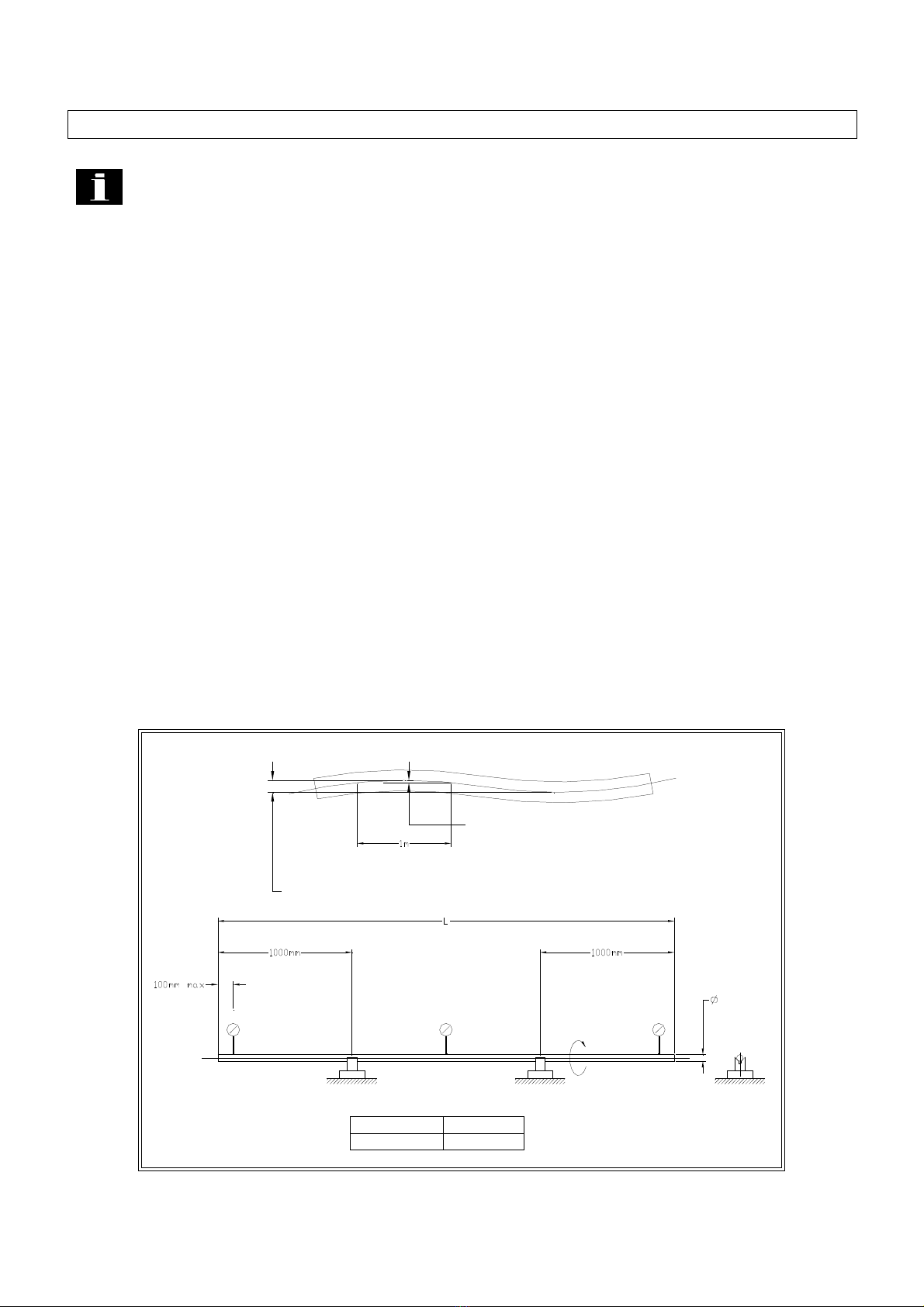
2.7.2 Procedure for checking bar straightness (Reference ASTM B249)
1. Find a suitable surface to allow the bar to rest on V-blocks without any rocking movement.
2. Rotate the bar 360°. Record the dial indicator readings at each location.
3. Calculate both the tolerance for each meter increment and also the tolerance over the entire
length of bar. Compare the recorded values to the required tolerances to determine the bar
suitability for operation with a bar feeder.
ROTATE
BAR 360?
1.7mm GEOMETRIC
TOLERANCE ZONE OVER TOTAL LENGTH
INCREMENTS
0.5mm TOLERANCE ZONE FOR
EACH METER INCREMENT
? .7MM / 3800MM
? .5MM / METER ? .070" / 12 FT
? .020" / 36"

2. Technical Information Patriot Series
8
2.7.3 Bar Stock Preparation
The bar stock must be free of burrs, chips and excessive dirt. Clean bars will extend the life of
the channel guides and bearing unit of the pusher as well as the oil pump impeller. The bar
ends should be relatively square to the length of the bar.
Chamfers on the bar ends are generally not needed except when the stock OD is close to the
bar pusher OD. In this case the wall of the pusher collet is thin and has only a small lead-in
chamfer.
Profiled material such as hex and square stock should have a generous chamfer on the bar
feeder end of the bar. This chamfer will help negate the offset of the bar centerline to that of the
bar pusher when the stock falls differently into the channel (corners up versus flats up).
Chamfers on the lathe end of the bar are not usually required, only an edge break to ensure no
burrs remain to snag on the lathe collet.
2.7.4 RPM Limiting Factors
Certain conditions may limit the lathe to less than full speed rotation of the spindle. Among
these conditions are the following:
•Bent bars (bar stock with straightness of less than .5mm/1 meter.
•Bars with an irregular profile or shaped material.
•Improperly sized guide channel in relation to the bar stock diameter.
•Incorrect sizing of guide blocks or incorrect adjustment of steady rollers.
•Lack of support in the lathe spindle for the bar pusher.
•Characteristics of the bar stock (copper, brass, plastic ect.).
•Improper viscosity lubricant in the oil tank of the bar feeder.
•Unbalanced bar stock.
•Sheared bar ends.
•Non-concentric chamfered bar end when using an ejection collet.
These factors may work alone or in combination to cause a vibration that requires a reduction in
the lathe spindle speed.

3. Transportation and Handling Patriot Series
9
A.
C.
B.
3. Transportation and Handling
Warning The weight of the bar feeder without packaging is approximately 2100 lbs.
Verify the equipment to be used for moving the bar feeder is rated to safely lift the
weight of the bar feeder plus the packaging material. Make special note that the bar
feeder is top heavy and take proper precautions.
3.1 Packaging of the Bar Feeder
The bar feeder will arrive in one of three ways:
A: Without packaging.
B: Attached to a skid or pallet.
C: Crated in a wooden box.
3.2 Transporting the Bar Feeder
The bar feeder will usually arrive in configuration “B”, on a skid. In configurations B and
C the machine may be lifted by a fork truck having suitable capacity. The forks must be
spread as far as possible, ideally under the stands of the bar feeder. Lifting straps may
also be used to move machines in the B and C configurations.
3. Transportation and Handling Patriot Series
10
D
F
E
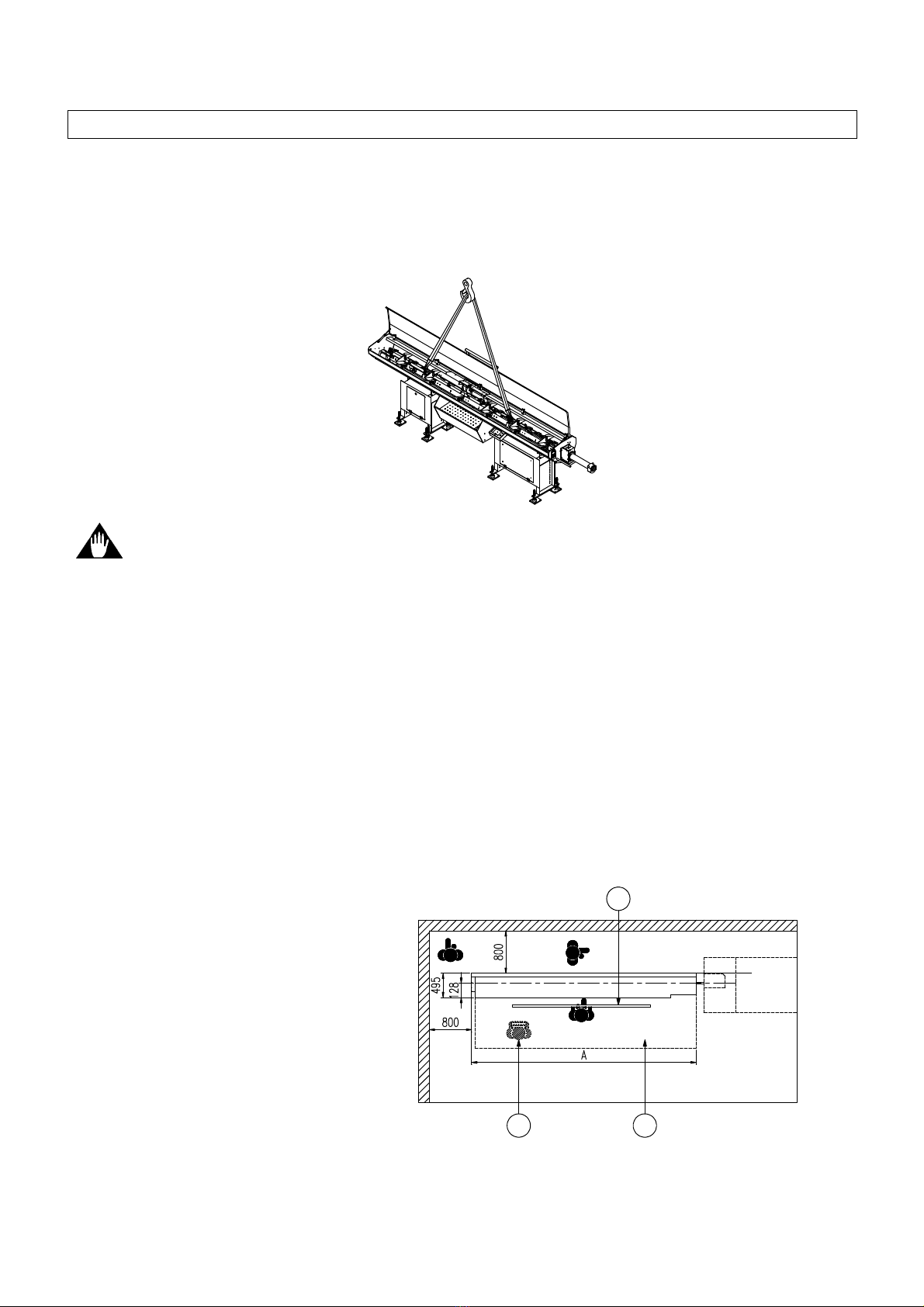
Machines in configuration “A” may be lifted only by the two 25mm eyebolts found under
the hood on the bar plane. These eyebolts must also be used to remove the bar feeder
from the skid.
Caution Lifting the bar feeder under the magazine with a lift truck or slings may cause
damage to the machine. Use the provided eyebolts with lifting straps or chains to
prevent damage to the bar feeder.
3.3 Installation Area
The bar feeder must be bolted to a sound, reasonably level floor using anchor bolts.
The area surrounding the machine must provide sufficient clearance the operator
access to both sides and the rear of the machine as shown in the diagram below.
Other necessities are suitable lighting and a compressed air supply. The bar feeder
is not suitable for and can not be adapted to use in an explosive surrounding.
A = 4400mm
D = Operator area
E = Material supply area
F = Remnant removal area

4. Installation Patriot Series
11
Maximum
Extension
A
B
Fixed Headstock
Sliding Headstock
4. Installation
Caution The following instructions should be carried out only by skilled, trained
personnel. Proper alignment and installation is crucial to achieve optimal performance
of the bar feeder. Improper alignment can cause poor finish quality and out of tolerance
conditions on machined parts, damage to the bar feeder channels, pusher and collet
and damage to the actuator and spindle bearings on the lathe.
4.1 Lathe Preparation
Prior to beginning the bar feeder installation the lathe must be properly leveled. It is
strongly recommended that the lathe be anchored to the floor to prevent it from shifting.
4.2 Distance From Lathe
The bar feeder must be set the proper distance from the lathe. This distance is measured from
the front of the anti-vibration device to the face of the lathe collet. In the case of a Swiss style
lathe the measurement is taken from the face of the lathe collet when the sliding headstock is in
over-travel condition nearest the guide bushing. Please refer to the diagram and chart below for
the correct dimension for bar feeder placement. The bar feeder is available in two pusher length
configurations, designated “L” for the shorter version and “LL” for the longer version.
A Dimension B Dimension L B Dimension LL Max Extension L Max Extension LL
3800 2870 2540 1120 1450
4. Installation Patriot Series
12
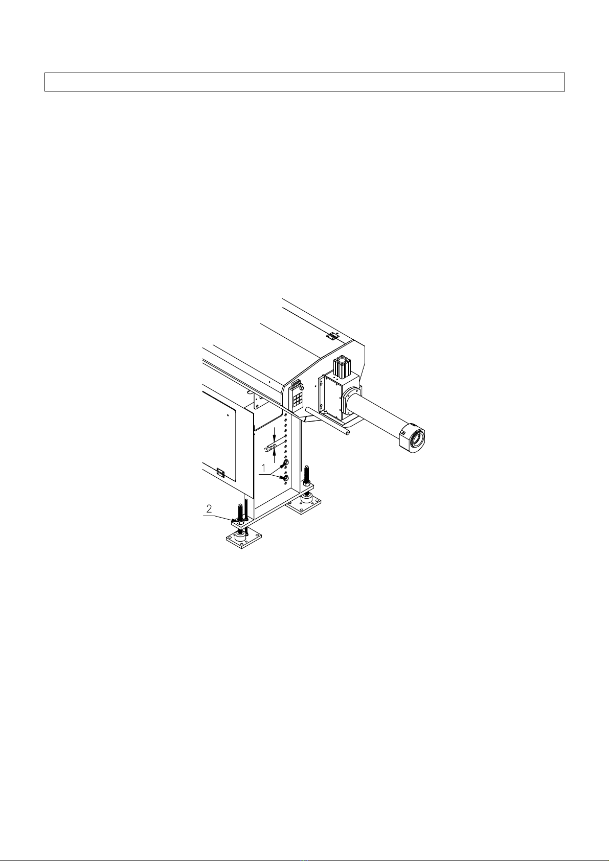
4.3 Height Adjustment
Determine the distance from the floor to the center of the spindle of the lathe. Compare this
dimension to the distance from the bottom of the bar feeder stand to the center of the opening of
the steady device plus 75mm. If this distance is not within 25mm ± of the lathe center height
the bar feeder stands must be adjusted by repositioning the legs on the bar feeder stands. The
spacing between the holes of the legs are 35mm. The legs can be adjusted without use of a
crane or lift truck by supporting the stand with one set of legs while moving the opposite set.
The height adjustment need not be exact at this point. The final adjustment will be made during
the alignment to the lathe.
4.4 Leveling
Place steel anchor plates and spacers under the four outside corners of the bar feeder. Thread
the leveling bolt into the stand so the ball of the tip is in the matching socket of the spacer.
Assemble the 10mm hold down rod as shown below, nut – lock washer – flat washer. Be
careful not to extend the rod past the bottom of the anchor plate. Tighten the nut at the anchor
plate. Do not tighten the nuts on the top and bottom of the stand at this time. Leave sufficient
clearance to allow for height adjustment and leveling. Place a machine level on the leveling
bracket. Level the bar feeder side to side at the front stand. Move to the rear stand and level
from side to side, then adjust for level front to rear. The front to rear level is only a coarse
adjustment at this time. Raise or lower the bar feeder to match the lathe center height while

4. Installation Patriot Series
13
maintaining the side to side level while performing this step. Once the center height is roughly
the same as that of the lathe you are ready to align the bar feeder.
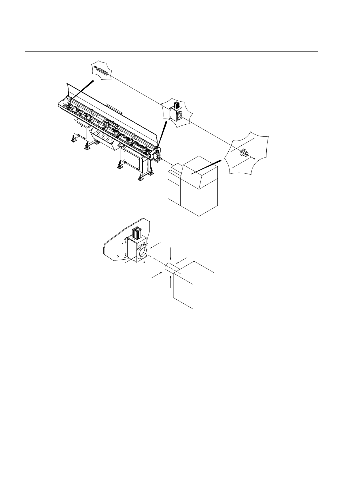
4.5 Alignment
The bar feeder is aligned to the lathe spindle by use of a nylon string which is stretched between
the lathe collet/chuck and the alignment fitting at the rear plate of the bar feeder. This string
indicates the centerline of the two machines. The procedure is detailed in the following steps.
4.5.1 Prepare the bar feeder
The bar feeder should be at the proper distance from the lathe, leveled from side to side and
adjusted to the approximate center height of the lathe as detailed in steps 4.2 – 4.4.
1. Open the guide channel and remove the bar pusher and pre-feed pusher.
2. Insert the nylon string through the hole in the supplied stepped plug and insert the plug into
the lathe collet.
3. Pull the string through the lathe spindle and the bar feeder and through the hole in the
alignment fitting in the rear plate of the bar feeder. Stretch the string as tightly as possible
and secure it to prevent slippage that would loosen the string.
4. Installation Patriot Series
14
C
D
B
A
4.5.2 Aligning the center lines
The bar feeder is aligned by moving the front and rear stands so that the distance from the
string to the centerline of the lathe spindle and the centerline of the opening of the anti-vibration
device is equal on all sides to within 0.15mm (approx. .005 inch).
1. Beginning with the rear stand, adjust the elevation by using the leveling screws so the rear of
the spindle is centered over the string between the 6 and 12 o’clock positions. A piece of
magnetic stock, such as that used in flat advertising magnets, attached to the spindle face
and positioned closely to the string will allow the spindle to be rotated 180 degrees to check
the position relative to the spindle bore. Once the string is centered to the spindle, move to
the front stands and repeat the procedure. To check the centering for the front of the bar

4. Installation Patriot Series
15
feeder check the position of the string relative to the bore of the anti-vibration device. It may
be necessary to alternate between the front and rear adjustments until both are centered.
When centered, tighten the jam nuts on the leveling screws.
2. Starting with the rear stand align the bar feeder to the lathe spindle from side to by using a
pry bar to shift the feeder. Small adjustments in position may be made by striking the anchor
plate with a soft faced hammer. When the string is centered to the spindle move to the front
stand and repeat the procedure, aligning the string to the bore of the anti-vibration device.
As with the elevation adjustment it may be necessary to alternate between the front and rear
adjustments until both are centered.
Important Information The bar feeder must be properly affixed to the floor to be
able to maintain alignment to the lathe. Bar feeders not anchored to the floor are subject
to damage to bar pushers, collets, anti-vibration blocks and guide channels as well as
possible damage to the machine tool.
4.5.3 Anchoring the bar feeder
The bar feeder is secured to the floor through hold down rods attached to the four leveling
plates which are bolted to the floor with concrete anchors. Please refer to the drawing in section
4.4. The anchor plates have 4 through holes for securing the plate to the floor. Only three holes
are used per plate.
1. Drill one hole through each of the four anchor plates using a rotary percussion
hammer drill equipped with a ½ inch diameter bit capable of drilling at least 8 inches
deep, preferably capable of drilling completely through the concrete. Drilling through
the concrete will make driving the anchors below flush possible if the machine is
to be relocated.
2. Drive an anchor bolt into each hole and tighten securely. Recheck the alignment to
verify that the feeder has not shifted (a small amount of shift is normal and may be
corrected later in the procedure).
3. Drill the remaining 2 holes per plate, insert and tighten the anchor bolts as above.
4. Tighten the top nut on each hold down rod.
5. Recheck the alignment. If the feeder has shifted loosen the hold down nut and ad-
just the leveling screw as required. Once the alignment is verified tighten the middle
Other manuals for Patriot Series
1
This manual suits for next models
2
Table of contents


