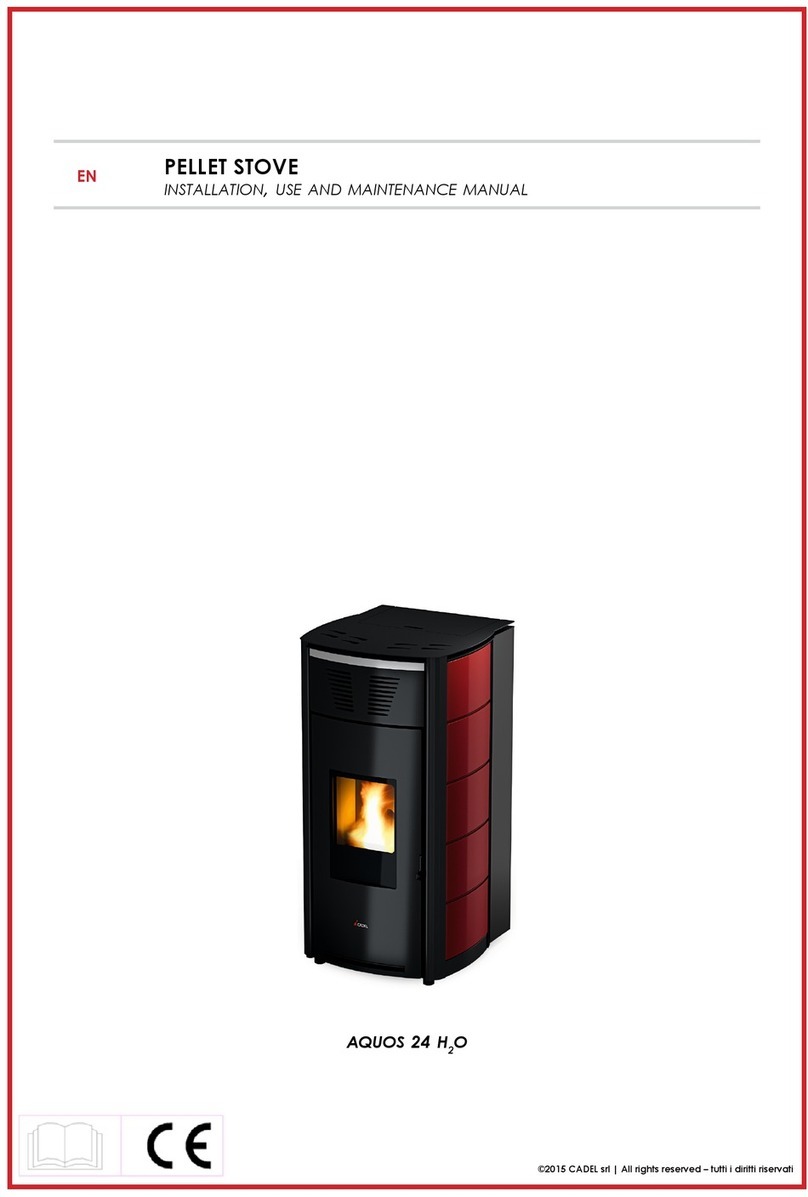
Olivieri ERGOFLAM IDRO User manual

Page | 0
Industrie Olivieri S.p.A
Installation
Instructions
ERGOFLAM IDRO & ERGOFLAM AIR
For Use in UK and ROI
This product is suitable for use in the stated countries. To install the product in other countries it is essential to
obtain translated instructions and in some cases the product may require modification.

Page | 1
LIST OF CONTENTS
Preamble Page6
Chapter1Introduction page7
1.1 Guarantee conditions page 7
1.2 Product size and construction features page 9
1.3Producttechnicalfeatures page11
1.4Fuelfeatures page13
Chapter2Installation page15
2.1Indoorpositioning page15
2.2 Fume extraction flue features page 18
2.2.1 Outside wall extraction page 20
2.2.2 Roof extraction by means of traditional flue page 21
2.3 Hydraulic connection features (ERGOFLAM IDRO) page 23
2.4 Control board wiring diagram page 26
2.5 Product covering assembly instructions page 28
Chapter 3 Use of the product page 32
3.1Controlpanel page34
3.2Lightingforthefirsttime page38
3.3Conditionsforuse page40
3.4 Safety devices page 43
3.5Usermenu page45
3.6One-wayradiocontrol page53
Chapter4Maintenance page54
4.1Scheduledmaintenance page54
4.2Yearlymaintenance page58
4.3 Unscheduled maintenance page60
4.4Troubleshooting page62

Page | 2
Dear Customer
First of all we would like to thank you for the trust you have placed in us when
purchasing one of the Olivieri products.
We have prepared this short manual for you in an attempt to make it as easy as
possible for you to use our product.
We also advise you to show the specific technical information given on the following
pages to those in charge of assembling the unit and making the product operational so
that these operations can be carried out as correctly as possible.

Page | 3
PREAMBLE
We would like to help you understand our manual by listing briefly the meaning
of the symbols characterising the most important and significant information
given:
"Warnings and safety
i Important information
Olivieri accepts no liability for any damage caused to people or property
because of failure to observe the simple rules of installation and use, described in
this manual.
You are also reminded that in installing the product you must observe relevant
national and local building regulations.
In pursuing continuous improvement of its products and customer satisfaction,
Industrie Olivieri S.p.A reserves the right to make all necessary modifications to
improve the quality level of its products, without prior notice.

Page | 4
1. INTRODUCTION
1.1 Guarantee conditions
Industrie Olivieri S.p.A . guarantees its products against any construction fault
and any material defect, that has been confirmed by the company, throughout
the Country.
- 5 years for wood-burning stoves;
- 2 years for wood-burning heaters;
- 2 years for pellet-burning heaters.
Repairs and replacements under guarantee of parts or products may be made,
at the discretion of Industrie Olivieri S.p.A., at the user’s address or at its own
plant, charging only carriage costs. Apart from this repair or replacement, the
user may in no case make any claims for compensation for damages of any
kind. The parts or products replaced under guarantee are the property of
Industrie Olivieri S.p.A. and they must be returned to the latter at the user’s
expense. Technical assistance work not under guarantee involves the fixed call-
out charge, costs of labour and materials required for repair according to the
current spares price list.
The following are not covered by guarantee:
1. Damage during transport (scratches, dents, etc.);
2. Damage due to incorrect installation of the product or to defects caused
by insufficiency or unsuitability of the flue, wiring, water, power or
drainage systems, or damage arising from environmental conditions due
to climate, etc.;
3. Damage caused by carelessness, negligence, tampering, misuse, or
repairs made by unauthorised personnel;
4. Parts made of ceramic, glass, brass, wood, handles, grips, gaskets,
external pipes and any other fittings;
5. Parts treated in galvanising bath, painted parts subject to wear and tear
from fire;
6. Deformities associated with the natural and physical features of the
materials used (any tile discolouring);
7. Installation and regulation of the equipment;
8. Plant consultancy and convenience checks;
9. Maintenance, such as cleaning of filters, nozzles, burners, heat
exchangers and circulators;
10. Anything that may be considered to be normal deterioration through use.
The equipment will be restored, within the time limits compatible with Industrie
Olivieri S.p.A.’s organisational requirements, following the user’s request to:

Page | 5
Repairs or replacements made under guarantee do not give rise to extensions or
renewals of the said guarantee. Any fault of the equipment must be reported by
registered letter with A.R. to Industrie Olivieri S.p.A. within two months from the
date detected. No-one is authorised to alter the guarantee terms and conditions
or to issue other verbal or written ones, apart from Industrie Olivieri S.p.A.. The
Company is not liable for any damage caused to persons or property from
breakdown or forced suspension of use of the equipment.
Industrie Olivieri S.p.A. reserves the right, at any time and at its own final
discretion, to make all the changes it considers useful or necessary to technical
data and features of its own products without this having any effect on the
above-mentioned general conditions.

Page | 6
1.2 Product size and construction features
We show below the main dimensions of the pellet heater, both in the air and in
the water version.
ERGOFLAM AIR:
Typical Dimensions (Air)
Height 1042 mm
Width 580 mm
Depth 580 mm
Weight 250 kg
Fume outlet diameter 80 mm
Air intake diameter 60 mm
Tank capacity 28 kg

Page | 7
ERGOFLAM IDRO:
Typical Dimensions (Water)
Height 1042 mm
Width 580 mm
Depth 580 mm
Weight 250 kg
Fume outlet diameter
80 mm
Air intake diameter
60 mm
Water pipe diameter ¾”
Tank capacity
28 kg
Boiler capacity 10 l

Page | 8
1.3 Product technical features
Our products are in conformity with EN 13240/2001 (solid-fuel household
equipment) and subsequent amendments, and already in line with the draft of
European standard EN 14785 (pellet-heating household equipment).
They are also in accordance with legal provisions, that incorporate the following
directives:
- 89/336 EEC (EMC directive) and subsequent amendments;
- 73/23 EEC (low voltage directive) and subsequent amendments;
- 89/106 EEC (fitness for use) and subsequent amendments.

Page | 9
Below is a short and simple note on the main performances and fittings of our
product:
ERGOFLAM AIR:
PERFORMANCE Min 2.6Rated thermochemical
capacity [kW] Max 11.5
Min 2.1Overall capacity [kW] Max 10.4
Min 1.9Working capacity [kW]
Max 8.8
Start-Up 310.5Power requirements [kW] Rated 155.5
Combustion gas
temperature ºC 170
Mass flow of gases burnt
[g/s] 9
Minimum draught [Pa] 10
CO values [%] < 0.04
Max. heatable volume [m3] 260 *
Min 86Overall efficiency [%]
Max 90
Min 0.7Pellet consumption [kg/h] Max 2.5
at nominal flow 11.5Autonomy [h] at minimum 42.5
MAIN FITTINGS
Controlled combustion system with fume temperature
recovery Serial
Fume draught control pressurestat Serial
Dual combustion system Serial
Airtight chamber operation Serial
Self-cleaning glass Serial
One-way radio control Serial
Automatic relighting in the event of blackout Serial
5-speed forced ventilation Serial
Possibility of setting power (5 levels) Serial
Weekly programmer Serial
Two-way radio control Optional
GSM module Optional
* values calculated on the basis of act 10/91 for rooms with thermal requirement of 30
kcal/hm3and height of 3 m. The data given above are approximate; the producer
company reserves the right to make any change in order to improve the product’s
performance.

Page | 10
ERGOFLAM IDRO:
PERFORMANCE Min 4.7Rated thermochemical
capacity [kW] Max 14.5
Min 4Overall capacity [kW] Max 13
Min 3.1Working capacity [kW]
Max 10.3
Start-Up 310.5Power requirements [kW] Rated 60.5
Maximum working water
pressure [bar] 1.5
Combustion gas
temperature ºC 170
Mass flow of gases burnt
[g/s] 9
Minimum draught [Pa] 10
CO values [%] < 0.04
Max. heatable volume [m3] 320 *
Min 86Overall efficiency [%]
Max 90
Min 1Pellet consumption [kg/h] Max 3.1
at nominal flow 9Autonomy [h] at minimum 28
Boiler capacity [litres] 10
MAIN FITTINGS
Controlled combustion system with fume temperature
recovery Serial
Fume draught control pressurestat Serial
Dual combustion system Serial
Airtight chamber operation Serial
Self-cleaning glass Serial
One-way radio control Serial
Automatic relighting in the event of blackout Serial
Water temperature monitoring Serial
Possibility of setting power (5 levels) Serial
Weekly programmer Serial
Two-way radio control Optional
GSM module Optional
* values calculated on the basis of act 10/91 for rooms with thermal requirement of 30
kcal/hm3and height of 3 m. The data given above are approximate; the producer
company reserves the right to make any change in order to improve the product’s
performance.

Page | 11
The results in the table were obtained using certified pellet based on Austrian
and German standards DIN 51731, DIN PLUS and ÖNORM M 7135.
You are reminded that the ESC (European Standardisation Committee) is in the
process of defining future European technical standards that will govern both
the technical features of this fuel and the economic and environmental aspects
associated with the production line.

Page | 12
1.4 Fuel features
The main feature of this heater is that it burns a natural fuel (the pellet) obtained
in an environmentally-friendly way from scraps of the timber industry (wood
chippings, sawdust, etc.).
Wood chippings and sawdust from wood products, after having been duly
recleaned and dried, are compacted in state-of-the-art very high-pressure
plants, into pure rounded wood pieces: the pellet. Each rounded piece can
have variable lengths and thicknesses, respectively between 1÷3 cm in length
and 6÷8 mm in diameter. The pellet’s main features are low moisture content
(below 12%), its high density (=600 kg/m30 as well as its regularity and
compactness that give this type of fuel characteristics of high calorific power
(I.C.P. 4000÷5000 kcal/kg).
Figure 1.1: Wood in pellet form.
The pellet to be used to feed the heater must have high quality characteristics
such as, those defined by standards DIN 51731 and ÖNORM M 7135, some basic
details of which we set out below.
Quality standard for
wood in pellet form Unit of
measurement Onorm M7135 DIN 51731 DIN plus
Diameter Mm from 4 to 10 from 4 to 10 from 4 to 10
Length Mm 5 x D1 < 50 5 x D1
Density Kg/dm3 >1,12 1,0 /1,4 > 1,12
Moisture Content % < 10 < 12 < 10
Ashes % < 0,50 < 1,50 < 0,50
Calorific Power Kwh/kg > 5 4.86 / 5.42 >5
Sulphur % < 0,04 < 0,08 < 0,04
Nitrogen % < 0,3 <0,3 <0,3
Chlorine % < 0,02 <0,03 <0,02
Powders % weight <2,3 - <2,3
Binding agents % of pressed mass <2 2 <2
1Not more than 20% of the pellet may have a length greater than 7.5 times its diameter D.
2The DIN prohibits the use of any added substance. However, this prohibition is not valid for small
heating systems.
DIN plus proposes the combination of the qualitative parameters proposed by
standard DIN 51731 and by Austrian standard Önorm M 7135.

Page | 13
i The pellet, as also stipulated by current Italian legislation governing the
commercial
technology characteristics of fuels (DPCM 2.10.1995) must be produced
exclusively with untreated wood chippings, with no other added materials.
"It is strictly prohibited to use any solid or liquid fuel other than the pellet to
feed the stove.
i In order to optimise the use of the product we recommend using pellets
which have been given a quality certificate by an authorised body. The
use of pellets other than those directed by the installer may lead to heater
malfunction and to the guarantee becoming invalid.
Storing and even moving the pellets are important operations to be
carried out with care:
•The fuel must be stored in a dry place away from cold;
•The pellets must be moved so as to avoid excessive crumbling
into fine dust.
Observance of these two simple rules makes it possible both to obtain
better fuel efficiency and to preserve the mechanical moving parts of the
apparatus.
"If the product is kept out of service for long periods of time (over fifteen
days), the tank must be emptied of any residual fuel, in order to prevent
any excessive dampness of the fuel causing the product to malfunction.
i A high moisture content in the pellet may cause it to crumble into dust,
that creates a greater accumulation of residue in the brazier area and
blockage of the fuel feed system (auger).

Page | 14
2 INSTALLATION INS.
TALLAZIONE
Before installation of this product please read these instructions fully.
It is very important to also understand the requirements of the UK and ROI
Building Regulations
BUILDING REGULATIONS - ENGLAND & WALES– Document J
BUILDING REGULATIONS - REPUBLIC of IRELAND- TG Document J
BUILDING REGULATIONS - NORTHERN IRELAND- Part L
BUILDING STANDARDS - SCOTLAND- Part F
BUILDING REGULATIONS - ISLE of MAN Document J
Along with any local regulations that may apply. Should any conflict occur
between these instructions and these regulations the regulations shall apply.
Your local Building Control Officer would be happy to advise should questions
arise regarding
the requirements of the regulations.
Olivieri products should be fitted by a HETAS approved installer, or approved by
your local
Building Control Officer.
A faulty installation could cause danger to the inhabitants and structure of the
building.
All heating systems should be designed by a competent heating engineer, and
be suitable
for a Solid Fuel appliance.
HETAS- P0 Box 37, Bishops Cleeve, Glos GL52 9TB.. Tel No: 01242 673257
Approved Document J of the Building Regulations. Copies can be obtained from
HMSO. Advice is also available from Local Authority Building Control
Departments.
Part F of the Building Regulations: Technical Standards Copies can be obtained
from Scottish Building Standards Agency
Part L of the Building Regulations. Copies can be obtained from Building control
northern ireland.
Guidance Document J of the Building Regulations. Copies can be obtained from
The Department of Environment (ROI) .

Page | 15
2.1 Indoor positioning
Our product, both in the AIR and the IDRO version, is a heater that draws air that
is necessary for its combustion process directly from the environment to be
heated.
For this reason and for the even more important reason of safety for the people
using it, the heater must be installed in a sufficiently ventilated place in order to
guarantee a continuous flow of air at all times.
It is therefore essential to make air vents connected to the outside. See example
in figure 2.1
Figure 2.1: Example of making an air vent.
i Important to also understand the requirements of the UK and ROI Building
Regulations (see 2: Installation)
Detail A

Page | 16
1.They must have a clear space of not less than cm2;
2.They must be made at a height close to the floor;
3.They must be suitably protected by a wire mesh or grille in such a way
that the minimum passage space is not and may not be reduced;
4.They must be placed in such a way that they are not obstructed in any
way.
i The correct inflow of fresh air may be guaranteed by using apertures
towards an adjacent room, provided that it has direct ventilation, and it is
not an environment with a fire hazard, such as store-rooms, garages or
warehouses, as regulated (See :2 INSTALLATION)
Our heater should be installed in rooms where there is no equipment operating in
airtight conditions in relation to the room, or apparatus that may place the room
itself in a vacuum in relation to the outside environment and thus cause
problems of poor draught for our product
i Combustion products from our heater must not be extracted into shared
flues.
When checking equipment compatibility, it is good practice to check whether
the support plane (floor) has a bearing capacity (kg) that is suited to the weight
of the product it must sustain. If not, correct safety measures must be taken (eg.
Load-distribution plate).
When installing the heater, it is advisable to plan a suitable distance from the
walls of the room in order to provide any access necessary both in the rear (at
least 20 cm is recommended) and to the side of the product (80 cm is
recommended) (for example to carry out appropriate cleaning work correctly).

Page | 17
i Having placed the outermost overall part of the heater at a distance of 80
cm from combustible and/or flammable material, if this distance cannot
be maintained it is useful to arrange for heat protection to be provided .
i Do not get close to, and above all do not touch with flammable material
the outer surfaces of the combustion chamber that, after continuous
product use, may reach high temperatures (See Section 2 INSTALLATION)
If the floor is made of combustible material (eg. parquet), it is advisable to
protect it using a sheet of non-combustible material placed underneath and
around the heater.
Figure 2.2: Protecting a floor made of combustible material.

Page | 18
2.2 Fume extraction flue features
The main features characterising the fume extraction flue are given. They are
based on what is set out in standards (See Section 2 INSTALLATION)
- Inspection valves (I);
- Maximum height of the pipe directly connected to the heater fume
extraction outlet must be between 2 - 3 m;
- If it is necessary to have a horizontal section, it is advisable to make it with
a maximum length of 1.5 m and with an incline of 3 - 5% in order to help
the fumes to escape;
- Use of a cowl that is wind-resistant and rain-resistant in order to avoid a
change in the slight condition of overpressure the flue is in;
i The reduction in pressure in the flue is necessary so as to help the normal
flow of fumes from the combustion chamber towards the outside, in the
event of a mains power cut.
i Remember that excess heat disposal is managed in an optimum way from
the electronic control panel (modulation, switch-off stage, etc.).
- Flues must be made of appropriate materials to resist combustion
products and condensation;
- Duct insulation particularly on the outside part exposed to the weather.
i Avoid making completely horizontal sections.
INS

Page | 19
Figure 2.3: Fume extraction flue
i In the room where the heat generator must be installed, there must be no
fume- extraction hoods already in existence or installed, in order to avoid
depressing the atmosphere.
i The air vents must not be closed.
"Keep the flue clean, performing a cleaning operation at least once a
year; it is also advisable to clean both the flue cowl and the fume pipe
connection.
This manual suits for next models
1
Table of contents
Popular Pellet Stove manuals by other brands
RED
RED PRIMULA HYDRO Use and maintenance manual

Enviro
Enviro Omega Specifications

Div Impex
Div Impex DA VINCI DV 140 W1 user manual

Travis Industries
Travis Industries AGP PS user guide

Heatilator
Heatilator ECO-ADV-PS35 owner's manual

Harman Stove Company
Harman Stove Company PC 45 Installation and operating manual