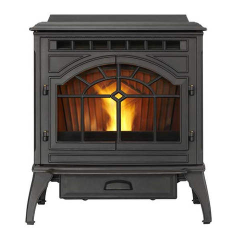
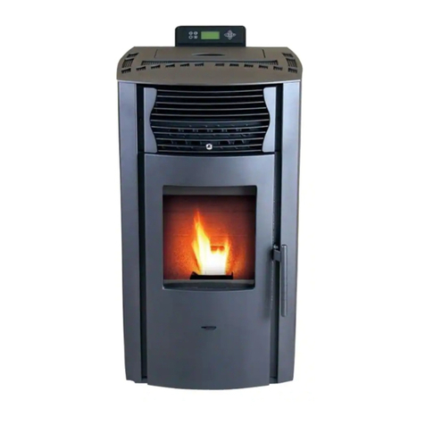
Comfort Bilt HP60I User manual

WARNING
PLEASE READ THIS ENTIRE MANUAL
BEFORE INSTALLATION AND USE OF
THIS PELLET FUEL-BURNING ROOM
HEATER. FAILURE TO FOLLOW
THESE INSTRUCTIONS COULD
RESULT IN PROPERTY
DAMAGE,BODILY INJURY OR EVEN
DEATH
CAUTION
DO NOT DISCARD!
●IMPORTANT OPERATING AND AINTENANCE
INSTRUCTIONS INCLUDED.
●SAVE THESE INSTRUCTIONS AND LEAVE
THIS MANUAL WITH ANY PARTY RESPONSIBLE
FOR USE AND OPERATION
CAUTION
CONTACT LOCAL BUILDING OR FIRE
OFFICIALS ABOUT RESTRICTIONS
AND INSTALLATION INSPECTION
REQUIREMENTS FOR YOUR AREA.
Operator’s Manual
HP60I
Pellet Insert
HP60I
Revised 07-05-14
©2014 SMG Hearth and Home LLC
All Rights Reserved

Operator’s Manual
HP60I Pellet Insert
~ 2 ~
WARNING
PLEASE READ THIS ENTIRE MANUAL BEFORE
INSTAL-LATION AND USE OF THIS PELLET
FUEL-BURNING ROOM HEATER. FAILURE TO FOLLOW
THESE INSTRUCTIONS COULD RESULT IN PROPERTY
DAMAGE, BODILY INJURY OR EVEN DEATH.
●DO NOT STORE OR USE GASOLINE OR
OTHER FLAMMABLE VAPORS AND LIQUIDS IN THE VICIN
ITY OF THIS OR ANY OTHER APPLIANCE.
●DO NOT OVERFIRE - IF ANY EXTERNAL
PART STARTS TO GLOW, YOU ARE OVERFIRING.
REDUCE FEED RATE. OVERFIRING WILL VOID THE
WARRANTY.
●COMPLY WITH ALL MINIMUM CLEARANCES
TO COMBUSTIBLES AS SPECIFIED. FAILURE TO COMPLY
MAY CAUSE A HOUSE FIRE
WARNING
HOT! DO NOT TOUCH. SEVERE BURNS MAY
RESULT. CLOTHING IGNITION MAY RESULT. GLASS
AND OTHER SURFACES ARE HOT DURING OPERATION AND
COOL DOWN.
●KEEP CHILDREN AWAY.
●CAREFULLY SUPERVISE CHILDREN IN SAME
ROOM AS APPLIANCE.
●DO NOT OPERATE WITH PROTECTIVE
BARRIERS OPEN OR REMOVED.
●KEEP CLOTHING, FURNITURE, DRAPERIES
AND OTHER COMBUSTIBLES AWAY.
CAUTION
DO NOT DISCARD!
●IMPORTANT OPERATING AND MAINTENANCE
IN-STRUCTIONS INCLUDED.
●READ, UNDERSTAND AND FOLLOW THESE IN-
STRUCTIONS FOR SAFE INSTALLATION AND OP- ERATION.
●LEAVE THIS MANUAL WITH PARTY
RESPONSIBLE FOR USE AND OPERATION.
CAUTION
CHECK BUILDING CODES PRIOR TO
INSTALLATION. CONTACT THE REGULATING
AUTHORITY PRIOR TO INSTALLATION TO DETERMINE
THE NEED FOR A PERMIT.
●INSTALLATION MUST COMPLY WITH
LOCAL, REGIONAL, STATE AND NATIONAL CODES AND
REGULATIONS
●CONSULT LOCAL BUILDING OR FIRE
OFFICIALS ABOUT RESTRICTIONS AND INSTALLATION
INSPECTION REQUIREMENTS IN YOUR AREA.
CAUTION
TESTED AND APPROVED FOR PELLET FUEL. BURNING
ANY OTHER TYPE OF FUEL VOIDS WARRANTY.

Operator’s Manual
HP60I Pellet Insert
~ 3 ~
WARNINGS AND SAFETY PRECAUTIONS
OWNER’S RESPONSIBILITY
Accurate assembly and safe and effective use of the stove
is the owners responsibility.
●
Read and follow all safety instructions.
●
Carefully follow all assembly instructions.
●
Maintain the stove according to directions and
schedule included in this operators manual.
●
Ensure that anyone who uses the stove Is familiar with all controls
and safety precautions
SPECIAL MESSAGES
Your manual contains special messages to bring attention to potential
safety concerns, stove damage as well as helpful operating and servicing
information. Please read all the information carefully to avoid injury and
stove damage
NOTE: General information is given throughout the manual that may
help the operator in the operation or service of the stove.
IMPORTANT SAFETY PRECAUTIONS
Please read this section carefully. Operate the stove
according to the safety instructions and recommendations outlined
here and inserted throughout the text. Anyone who uses this stove
must read the instructions and be familiar with the controls
This symbol points out important safety
instructions which if not followed could
endanger your personal safety. Read
and follow all instructions in this manual
before attempting to operate this
equipment.
DANGER
DANGER INDICATES A SERIOUS INJURY OR
FATALITY WILL RESULT IF THE SAFETY INSTRUCTIONS
THAT FOLLOW THIS SIGNAL WORD ARE NOT OBEYED.
WARNING
WARNING INDICATES A SERIOUS INJURY OR
FATALITY COULD RESULT IF THE SAFETY INSTRUCTIONS
THAT FOLLOW THIS SIGNAL WORD ARE NOT OBEYED.
CAUTION
CAUTION INDICATES YOU CAN OR YOUR
EQUIPMENT CAN BE HURT IF THE SAFETY
INSTRUCTIONS THAT FOLLOW THIS SIGNAL WORD ARE
NOT OBEYED.
IMPORTANT
IMPORTANT INDICATES HELPFUL INFORMATION
FOR PROPER ASSEMBLY, OPERATION, OR MAINTENANCE
OF YOUR EQUIPMENT.
WARNING
YOU MUST READ, UNDERSTAND AND COMPLY
WITH ALL SAFETY AND OPERATING INSTRUCTIONS IN
THIS MANUAL BEFORE ATTEMPTING TO SETUP AND
OPERATE YOUR STOVE.
FAILURE TO COMPLY WITH ALL SAFETY AND
OPERATING INSTRUCTIONS CAN RESULT IN SERIOUS
PER- SONAL INJURY TO YOU AND/OR BYSTANDERS, AND
RISK OF EQUIPMENT AND PROPERTY DAMAGE. THE
TRIANGLE IN THE TEXT SIGNIFIES IMPORTANT CAUTIONS
OR WARNINGS WHICH MUST BE FOLLOWED.

Operator’s Manual
HP60I Pellet Insert
~ 4 ~
WARNING
WARNING INDICATES A SERIOUS INJURY OR
FATALITY COULD RESULT IF THE SAFETY
INSTRUCTIONS THAT FOLLOW THIS SIGNAL WORD ARE
NOT OBEYED.
•Read this entire manual before you install and use
your new pellet stove. Failure to follow instructions may result
in property damage, bodily injury, or even death.
•Children and adults should be alerted to the hazards
of high surface temperatures and should stay away to avoid
contact to skin and/or clothing.
•Young children should be carefully supervised when
they are in the same room as the stove.
•Clothing and other flammable materials should not be
placed on or near this unit.
•Flammable or explosive liquids such as gasoline,
naphtha, alcohol, or engine oil must
NEVER
be used in
or around stove. These liquids must be stored in a
separate room as the open flame in the fire box could
ignite the fumes of such liquids.
•
DO NOT
burn garbage in this unit. The burning of
other solid fuels such as cord wood or wood chips in this
stove is not permitted. Any fuels not certified which are
burned in this stove will void the warranty.
•
DO NOT
route power cord in high traffic areas. A
power surge protector plugged into a grounded 230 volt
power source is required.
•
DO NOT
install a flue damper in the exhaust venting
system of this unit.
•
DO NOT
connect this unit to a chimney flue
servicing another appliance.
•
DO NOT
install in a sleeping room.
•
DO NOT
connect to any air distribution duct or
system.
•
DO NOT
connect directly to a masonry chimney.
•
DO NOT
terminate vent in any enclosed or
semi-enclosed area, such as; carports, garage, attic, crawl
space, under a sun deck or porch, narrow walkway or closed
area, or any location that can build up a concentration of fumes
such as a stairwell, covered breezeway etc.
•
NEVER
touch door latches while stove is in operation;
they get extremely hot.
WARNING
PROPER INSTALLATION OF THIS STOVE IS NECES-
SARY FOR SAFE AND EFFICIENT OPERATION. IN-
STALLING THIS PRODUCT IMPROPERLY MAY RESULT
IN A HOUSE FIRE AND PERSONAL INJURY.
ALL APPLICABLE BUILDING CODES FOR YOUR LOCA-
TION MUST BE FOLLOWED. IN AREAS WHERE BUILD-
ING CODES REQUIRE ADDITIONAL STEPS TO THE
INSTALLATION OF THIS PRODUCT NOT INCLUDED IN
THIS MANUAL, THE BUILDING CODES WILL TAKE
PRECEDENT AND MUST BE FOLLOWED. CONTACT
YOUR LOCAL BUILDING INSPECTOR TO OBTAIN ANY
NECESSARY PERMITS OR INSPECTION GUIDELINES
BEFORE INSTALLING THE PRODUCT.

Operator’s Manual
HP60I Pellet Insert
~ 5 ~
CAUTION
ALL APPLICABLE BUILDING CODES FOR YOUR
LOCATION MUST BE FOLLOWED. IN AREAS WHERE
BUILDING CODES REQUIRE ADDITIONAL STEPS TO THE
INSTALLATION OF THIS PRODUCT NOT INCLUDED IN THIS
MANUAL, THE BUILDING CODES WILL TAKE PRECEDENT
AND MUST BE FOLLOWED. CONTACT YOUR LOCAL
BUILDING INSPECTOR TO OBTAIN ANY NECESSARY
PERMITS OR INSPECTION GUIDELINES BEFORE
INSTALLING THE PRODUCT.
•Contact localbuilding or fire officials about
restrictions and installation inspection requirements in
your area.
•Contact your local authority (such as municipal building
department, fire department, fire prevention bureau, etc.) to
determine the need for a permit.
•This pellet stove is designed to burn pellet fuel
only.
•A working smoke detector is required and
must be installed in the same room as the stove.
•This stove is not intended for use in
commercial applications.
•Door andash pan must be closed and
latched during operation.
•Notify your insurance company of pellet stove
installation.
•This installation must conform with local
codes. In the absence of local codes you must comply
with EN 14785.
•The structural integrity of the
manufactured home floor, wall, and ceiling/roof
must be maintained.
•Keep combustible materials (such as
grass, leaves, etc.) at least three feet away from the
flue outlet on the outside of the building.
•This stove should not be used as the only
source of heat in the house. Power outages and
periodic maintenance will result in a total loss of
heat.
•Do not leave hopper door open while unattended.
CAUTION
INSTALLATION AND REPAIR OF THIS PELLET
STOVE SHOULD BE DONE BY A QUALIFIED SERVICE
PERSON. THE APPLIANCE SHOULD BE INSPECTED BEFORE
USE AND AT LEAST ONCE A YEAR BY A QUALIFIED
SERVICE PERSON. IT IS IMPERATIVE THAT THE CONTROL
COM- PARTMENTS, FIRE BOX, AND THE CIRCULATING AIR
PASSAGEWAYS OF THE STOVE BE KEPT CLEAN.
THE OPERATION OF EXHAUST FANS SUCH AS
BATH-ROOM FANS, ATTIC FANS, ETC. MIGHT STARVE THE
PELLET STOVE OF COMBUSTIBLE AIR CREATING A
NEGATIVE PRESSURE IN THE ROOM. PROVIDE ADE- QUATE
VENTILATION OF THE ROOM ACCOMPANYING
THE PELLET STOVE. IF NOT, THE PRESSURE
SWITCH
MAY SHUT OFF OPERATION OF THE PELLET
STOVE.
THE MOVING PARTS OF THIS STOVE ARE
PROPELLED BY HIGH TORQUE ELECTRIC MOTORS.
THESE PARTS CAN CAUSE SEVERE DAMAGE TO BODY
PARTS THAT GET NEAR THEM. KEEP ALL BODY PARTS
AWAY FROM AU- GER AND FANS WHILE THE STOVE IS
PLUGGED INTO AN
ELECTRICAL OUTLET. THESE MOVING PARTS
MAY BE-
GIN TO MOVE AT ANY TIME THE STOVE IS
PLUGGED IN.
THE VENT SURFACES CAN GET HOT ENOUGH
TO CAUSE BURNS IF TOUCHED. NONCOMBUSTIBLE
SHIELDING OR GUARDS MAY BE REQUIRED.
INSTALL VENT AT CLEARANCES SPECIFIED BY
THE VENT MANUFACTURER.
ALL VENTING JOINTS, WHETHER VERTICAL OR
HORI-ZONTAL, SHOULD BE MADE GAS-TIGHT WITH REC-
OMMENDED SEALANTS SPECIFIED BY VENT MANU-
FACTURER.
ACCORDING TO HUD (HOUSING & URBAN
DEVELOPMENT) REQUIREMENTS, WHEN INSTALLED IN A
MOBILE HOME, THIS STOVE MUST BE GROUNDED
DIRECTLY TO THE STEEL CHASSIS OF THE MOBILE
HOME AND BOLTED TO THE FLOOR. DIRECT
AIR ACCESS MUST BE PROVIDED, USE A
FRESH AIR KIT.
FOR USE IN THE UNITED STATES AND CANADA.
AP-
PROVED FOR INSTALLATION IN MOBILE
HOMES.
PRODUCER OF THIS APPLIANCE, RESERVES THE
RIGHT TO ALTER ITS PRODUCTS, SPECIFICATIONS AND/OR
PRICE WITHOUT NOTICE.
Operator’s Manual
HP60I Pellet Insert
~ 6 ~
INTRODUCTION
Congratulations on your investment in quality. We have worked to ensure that this pellet stove meets the highest standards for
usability and durability. With proper care, your stove will provide many years of dependable service. Please read entire manual before installation
and use.
BURNING PELLET FUEL
Ashes need to be removed from the stove periodically. See Normal Care &Maintenance section for cleaning procedure. Due to
the nature of pellet fuels, this stove will require attention periodically. Regular cleaning is an important part of burning pellet fuel.
PELLETS
•This pellet stove is designed and approved to burn wood pellets, that comply with pellet fuels industry standards. Minimum of
40 lbs. density per cubic feet, 1/4 to 5/16 in diameter, with a maximum length of 1-1/2, and less than 1% ash.
•Theperformance of your pellet stove is greatly affected by the type and quality of wood pellets. As the heat output of various
quality wood pellets differ, so will the performance and heat output of the pellet stove.
•Wood pellets are generally produced out of wood waste such as sawdust and shavings. The raw material is dried, mechanically
fractioned to size and extruded into pellets under high pressure. Wood pellets need to be protected from direct exposure to water. Water from
sources such as condensation and humidity causes pellets to expand and break down into unusable fuel. Keep fuel
dry.
•It is important to select and use only pellets that are dry and free from dirt and debris. Dirty fuel will adversely affect the operation
and performance of the unit and will void the warranty. The Pellet Fuel Institute (PFI) has established standards for wood pellet manufacturers.
Only use pellets that meet or exceed PFI standards for premium fuels.
CLINKERS
•Impurities, such as silica (clinkers), will need to be regularly cleaned and removed from the pellet stove. Clinkers will form a
hard mass and block airflow through the pot liner. High quality fuels will result in fewer clinkers
WARNING
IF THE ELECTRICAL POWER FAILS ANY TIME WHEN
THE STOVE IS HOT, KEEP ALL STOVE DOORS CLOSED.
THE AUTOMATIC SAFETY FEATURES MUST NOT BE
BYPASSED.
CAUTION
BURNING WOOD PELLETS ACCORDING TO
RECOMMENDATIONS WILL ASSURE LONGER
STOVE LIFE AND LESS FUEL RELATED
PROBLEMS.
THE USE OF GRATES OR OTHER METHODS
OF SUPPORTING THE FUEL IN THIS STOVE IS
PROHIBITED AND WILL VOID ALL
WARRANTIES
AUTOMATIC SAFETY FEATURES
POWER OUTAGE
During a power outage, the stove will shut down safely. Do not
open the main door or ash door.
During a power failure the exhaust fan will not run. Keeping the
doors sealed will allow the exhaust vent to draft out naturally.
When the power is restored, the stove will not restart. If the
exhaust temperature is still 120 degrees Fahrenheit when power is
restored, the exhaust and convection fans will continue to run until
the stove cools. See lighting instructions to restart stove.
OVERHEATING
Over Fire Protection:
If the stove is being
over fired or burning too hot, the high limit
switches will automatically shut down the stove to avoid
damage to components. If the temperature on the hopper
reaches 200 degree Fahrenheit, the auger will automatically
stop and the stove will shut down. The exhaust fan will
continue to run until the proof of fire switch cools. Allow
stove to cool before attempting to re-ignite. See lighting

Operator’s Manual
HP60I Pellet Insert
~ 7 ~
SPECIFICATIONS
Model Number HP60I
BTU/hour input (1)
4.8 lbs/hr
Heating Capacity (2) 1,200 sq. ft.
Electrical Rating 115 Volts, 60Hz
Power Consumption 520 Watts ignition 150 Watts operating
Fuel Storage Capacity 55 lbs
Flue Size 75mm
Width 599mm
Height 645mm
Depth 702mm
Weight 105kg
(1) Heat output will vary, depending on the brand, type and quality of fuel and the moisture content. Consult your dealer for best
results.
(2) Based on post 1982 home construction, requiring 35 BTU/ Hr. per Sq. Ft.
GLASS SPECIFICATIONS
This stove is equipped with ceramic glass. Replace glass only with Qualified ceramic glass.
UNPACKING
Your stove will come fully assembled. Remove all packing material and tape from the inside of the firebox. Remove
any tape on the outside of the glass. Open the hopper, remove all packing material and power cord.
NOTE: MAKE SURE THE HOPPER IS FREE OF ALL FOREIGN MATTER BEFORE FILLING WITH FUEL. FOREIGN MATERLAL WILL CAUSE AUGER
JAMS AND WILL VOID STOVE WARRANTY.

Operator’s Manual
HP60I Pellet Insert
~ 8 ~
INSTALLATION OVERVIEW

Operator’s Manual
HP60I Pellet Insert
~ 9 ~
General venting
!WARNING
Pellet vent must maintain a minimum 3" clearance to any combustible (install vent at clearances
specified by the vent manufacturer).
Do not connect the pellet vent to a vent or chimney serving any other appliance or heater.
Do not install a flue damper in the exhaust venting system of this unit.
1 Type of vent
Must be an approved 3" or 4" diameter Type "L" or "PL" vent, vented to the outside or connect the vent to a
factory built type "A" chimney using an adaptor; and/or stainless steel chimney liner for masonry fireplace
installations. Use 4" diameter vent if vent or liner height is over 15' or if installation is over 4,000' above sea
level.
2 installing the pellet vent
The vent must have a support bracket every 5' when on the exterior wall. To
achieve optimum performance, keep vent runs as short as possible,
especially on horizontal installations.
MAXIMUM VENTING: Maximum venting height is 33'. Maximum horizontal
vent run is 10'. Use no more than 180° of elbows (two 90' elbows, or two 45'
elbows and one 90' elbow, etc), excluding the tee and the termination.
VENT INSTALLATION: Termination must exhaust above the air inlet
elevation, and parallel or above the exhaust output of the pellet appliance. It
is recommended that at least 3' of vertical pipe be installed to create some
natural draft. This is to help prevent the possibility of smoke or odour
entering the home during the appliance shut down or in the event of a power
outage. Horizontal sections must have a 1/4" rise every 12" of travel if
longer than 3'.
The pellet vent connections must be sealed with HI-Temp RTV Silicone and
screwed together with at least 3-3/8" long stainless steel screws. Seal each
vent section by injecting a liberal amount of 500°F (260°C) RTV silicone
sealant into the gap. We recommend sealing the outside of the vent
connections to permit easier access when servicing.
3 venting the pellet heater
Use an approved wall thimble when passing the vent through walls and a
ceiling support / fire stop spacer when passing the vent through ceilings
(maintain a 3" clearance to any combustibles).
4 Pellet vent termination
The vent termination must have an approved cap (to prevent water from
entering) or a 45° downturn. If the termination is located on a windy side of the house, a shield is recommended to
prevent soot from building up on the side of the house.
Horizontal terminations must protrude 12" from the wall, vertical terminations require a minimum 24" above the
highest point that it penetrates through the roof.
Depending on pellet quality, vent configuration and air settings, black soot may occur on the terminal wall.

Operator’s Manual
HP60I Pellet Insert
~ 10 ~
5 Minimum Air Terminal Location Clearances

Operator’s Manual
HP60I Pellet Insert
~ 11 ~
installation
1 Masonry Heater installation
WARNING
Do not remove bricks or mortar from the fireplace.
Prior to installation:
Stand-offs may be removed to fit the insert into the fireplace.
When installing the insert into a masonry fireplace, do not
remove any bricks or masonry. Do not weaken the structure, or
reduce the protection for combustible materials to less then that
required by the National Building Code.
Bolted or screwed together pieces (smoke shelf / deflectors)
may be removed, but must be able to be re-installed if the
heater was removed.
External trim pieces, which do not affect the operation of the
fireplace, may be removed provided they are available to be
re-installed in event the heater is removed.
A warning label must be attached to the back wall of the
fireplace stating that “This fireplace has been altered to
accommodate a fireplace insert and must be re-inspected by a
qualified person prior to re-use as a factory built fireplace”.
A non-combustible hearth must cover the flooring underneath,
as well as extend a minimum of six inches in front and to both
sides of the heater.
Clean all ashes out of the inside of the fireplace. Make sure that
the chimney and fireplace are free of cracks, loose mortar,
creosote deposits, blockage or other signs of deterioration.
If necessary, have any repair work done by a qualified professional before installing
the heater.
A. Remove the fireplace damper or fasten it permanently open.
B. Measure the throat of the fireplace and mark this shape on a piece of 24 gauge sheet metal (flue cover). Cut a
hole sized for the pellet liner to lie directly below the fireplace flue opening. Allow two inches of material for a flange
on all sides and cut to these measurements. Bend down the flanges. If you have never done this before, it might be
a good idea to make a cardboard pattern and test it first. Fasten this flue cover in position as high as possible with
two masonry screws per side through the flanges into the fireplace.
C. If you plan on connecting outside air it is recommended to do so at this time.
D. Install floor protection if necessary.
E. Connect the pellet vent with a clean out tee to the back of the insert.
F. Run a liner down the chimney and connect to tee.
G. Position the insert in it's final location.
H. Pull the excess length of liner out through the top of the chimney. Trim the excess liner, install the cap and
cap the chimney.

Operator’s Manual
HP60I Pellet Insert
~ 12 ~
2 factory built (METAL) Heater installation
Prior to installation:
Stand-offs may be removed to fit the insert into the fireplace.
Do not weaken the structure, or reduce the protection for combustible
materials to less then that required by the National Building Code.
Bolted or screwed together pieces(smoke shelf / deflectors) may be
removed, but must be able to be re-installed if the heater was removed.
External trim pieces, which do not affect the operation of the fireplace,
may be removed provided they are available to be re-installed in event
the heater is removed.
A warning label must be attached to the back wall of the fireplace
stating that “This heater has been altered to accommodate a fireplace
insert and must be re-inspected by a qualified person prior to re-use as
a factory built fireplace”.
A non-combustible hearth must cover the flooring underneath, as well
as extend a minimum of six inches in front and to both sides of the
heater.
Clean all ashes out of the inside of the heater. Make sure that the
chimney and fireplace are free of cracks, loose mortar, creosote
deposits, blockage or other signs of deterioration.
If necessary, have any repair work done by a qualified professional
before installing the heater.
A. Remove the fireplace damper or fasten it permanently open.
B. Measure the throat of the fireplace and mark this shape on a piece
of 24 gauge
sheet metal (flue cover). Cut a hole sized for the pellet liner to lie
directly below
the fireplace flue opening. Allow two inches of material for a flange on
all sides
and cut to these measurements. Bend down the flanges. If you have
never done
this before, it might be a good idea to make a cardboard pattern and
test it
first. Fasten this flue cover in position as high as possible with two
masonry
screws per side through the flanges into the heater.
C. If you plan on connecting outside air it is recommended to do so at this time.
D. Install floor protection if necessary.
E. Connect the pellet vent with a clean out tee to the back of the insert.
F. Run a liner down the chimney and connect to tee.
G. Position the insert in it's final location.
H. Pull the excess length of liner out through the top of the chimney. Trim the excess liner, install the cap and
cap the chimney.

Operator’s Manual
HP60I Pellet Insert
~ 13 ~
3 INSTALLATION INTO A COMBUSTIBLE ENCLOSURE
WARNING
The stand-offs located on the back of the insert must not be removed when installing the insert into a
built-in combustible enclosure.
Outside air is mandatory for a combustible built-in enclosure install.
When installing the insert as a "Built-in" heater, it is important to maintain the clearances to combustibles, see
"MINIMUM CLEARANCE TO COMBUSTIBLES" section.
A non-combustible hearth must cover the flooring underneath, as well as, a minimum of six inches in front and
to both sides of the heater.
1) framing
A. Install floor protection.
B. Frame structure maintaining minimum clearances. Locate and frame openings for both the exhaust and
outside air. Outside air is mandatory for "Enclosure" installations.
C. Refer to the vent manufacturer's installation instructions and to "GENERAL VENTING" section. Connect
the vent.
D. Install surrounding Panel. See "HP60I Finishing - surrounding Panel Installation " section.
E. Consideration must be taken during installation that removal of the insert is necessary for inspection
and annual maintenance. Install the vent cap.

Operator’s Manual
HP60I Pellet Insert
~ 14 ~
2) minimum enclosure clearances
3) Minimum Clearance To Combustibles
Side wall to heater 8"
Mantel to top of heater 8"
Top facing to heater 6 3/8"
Side facing to heater 6"
Floor protection* 6"*
* Floor Protection: Minimum 6" in front of door
and to either side.

Operator’s Manual
HP60I Pellet Insert
~ 15 ~
4) Minimum Mantel Clearances

Operator’s Manual
HP60I Pellet Insert
~ 16 ~
INSERT FINISHING
1) surrounding Panel Installation
a:) slide the surrounding Panel assembly down over the insert body
B:)Secure the panel using the six M6×20 screws
2)connect the cable to control panel.

Operator’s Manual
HP60I Pellet Insert
~ 17 ~
BECOMING FAMILIAR WITH YOUR
CONTROLLER
Figure 17: Control pad key
CONTROLLER BUTTONS (SEE FIGURE 17)
1.
Infrared Receiver:
Receives signal from remote control. (Available
separately)
2.Power Indicator -
Illuminates when the main power switch is on.
3.
Alarm Light
- Illuminates if stove is not operating properly.
4.On/Of Button
- Starts and stops operation of stove.
5.Timer Button
- Allows you to choose the start time or shutdown time
of the unit.
6.Mode Transfer Button
- Allows you to set the unit to one of three
main mode settings: Manual, Temp, and Weekly
7.
Hold Button
- Pressing the “Hold”button in weekly mode after
raising the Call To temperature will maintain that temperature until the
button is pressed again or the stove
is shut down
8.Scroll Up Button
- Allows you to scroll up to choose items in the
menu.
9.
Exit Button:
Takes you out of current selection and returns to
previous option and/or screen. When entering data, pressing the EXIT
button will also delete your entries
10.Scroll Down Button
- Allows you to scroll down to choose items in
the menu.
11.Enter Button
-Pressing “Enter” button allows you to adjust and
select data on the screen. Pressing the ENTER button for two
seconds will take you to a main menu screen in which you’ll have the
ability to change the time, date, temperature display, weekly
operation schedule (for Weekly Mode only) and combustion
motor and voltage settings

Operator’s Manual
HP60I Pellet Insert
~ 18 ~
MAIN
OPERATION
CONTROLLER
SCREEN
DISPLAY
Figure 19
1.
Date and Time
: Displays time and date.
2.
Heating Power Level
: Indicates the level of power at
which the stove is currently heating
3.Current Room Temperature/Call To Temperature:
Displays current room temperature and, in the
thermostat mode, the call to temperature.
4.Main Mode:
Displays operation mode--weekly,
thermostat (temperature) and manual.
5.Work Stage:
Displaysoperational stage in which the
stove is currently operating (i.e. ignite, heating room).
6.Additional Control Mode
7.Ignitor Indicator:
Indicates ignition cycle/burning cycle
is currently happening
8.Combustion Blower Indicator:
Indicates combustion
blower is running.
9.Auger Indicator:
Indicates auger is feeding pellets
10.Convection Blower Indicator
: Indicates convection
blower is running and the fan is heating the room.
11.Vacuum Switch Indicator
: Indicates there is vacuum
pressure in the stove
12.
Hopper Lid Open Indicator (Limit Indicator):
If lit,
indicates the hopper lid is closed. When hopper lid is
open, this will disappear.
13.Hopper Lid Open Indicator (Limit Indicator):
If lit,
indicates the hopper lid is closed. When hopper lid is
open, this will disappear.

Operator’s Manual
HP60I Pellet Insert
~ 19 ~
PRE-OPERATION
Once the stove has been properly installed and plugged into
a grounded surge protector you are ready to begin operation.
PRIOR TO STARTING
Turn on the main power switch located on the surround panel
of the stove.
NOTE: IF FOR SOME REASON THE STOVE DOES
NOT APPEAR TO BE POWERING ON, THERE IS A
FUSE LOCATED JUST BELOW THE POWER SWITCH
THAT CAN BE CHECKED. SEE FIGURE 20B. NOTE
THAT THERE IS A SPARE FUSE LOCATED IN THE
FUSE HOLDER. See
Figure 20
Make sure the hopper is clean and free of foreign matter
including pellet fines and dust. Fill the hopper with wood
pellets, making sure that NO parts of the bag or any foreign
objects enter the hopper as this may cause harm to the auger
feed system.
Also take care in making sure there is no pellet material in the
hopper lid seating surfaces.
Close the lid. This stove has a safety switch that will not allow
pellets to feed with the hopper door open.
Make sure the main glass door is closed. The stove has a
safety switch that will not allow the stove to feed fuel unless
there is negative draft pressure inside the stove.
Before actually starting your Stove, you will need to determine
in which mode you would like to run the stove. This stove can
operate in three modes:
1.Manual
: Under this mode, you can personally adjust and
set the heating phase to control the heat level.
2.Thermostat Control (Temperature)
:Under this mode, you
can set the room temperature and the stove will
automatically run to ensure the room is at that temperature.
3.Weekly
: Under this mode, the stove will work automatically
during days and times you designate. You can have a
program for each of the seven days of the week and four
periods during the day
You must select your mode before turning on the stove.
Selecting a mode while the stove is burning may cause the
stove to shut down and may force a 30-minute delay in
restarting. You do not need to start operation of the stove to
select your mode. To choose the mode, select the mode
transfer button . Pressing the mode button once selects
the thermostat setting; selecting it twice will bring you to the
weekly mode
Figure 20:Main power switch
WARNING:
NEVER USE FLAMMABLE LIQUIDS SUCH AS
GASOLINE, GASOLINE TYPE LIGHTER FUEL, CHARCOAL
LIGHTER FUEL OR FIRE STARTING GELS IN OR AROUND
THIS STOVE. KEEP ALL SUCH LIQUIDS WELL AWAY FROM
THE STOVE WHEN IT IS IN USE.
NEVER OPEN SIDE PANELS OR MAIN DOOR
WHEN STOVE IS IN OPERATION.
NEVER TOUCH DOOR LATCHES WHILE IN
OPERATION, THEY GET EXTREMELY HOT.
NEVER OPEN GLASS DOOR WHILE STOVE IS
OPERATING OR WHILE STOVE IS HOT.

Operator’s Manual
HP60I Pellet Insert
~ 20 ~
OPERATION
After you have chosen the mode in which to operate
your stove, press the ON/OFF button to start the
stove ignite cycle
START UP
When the stove turns on, the ignition indicator and the combustion
blower indicator will appear on the screen (images and 8 in Figure 19
on page 23). “Ignite”will also appear in the work stage box on the
screen. After approximately four seconds, the vacuum switch
indicator will appear. Also note that the hopper lid open indicator
(limit indicator) will appear anytime the stoves hopper lid is properly
shut and sealed.
The stove motor will continue to run for three minutes, then the auger
indicator will flash on the screen, indicating that the auger if feeding
pellets into the stove. Within three to five minutes of the auger
feeding pellets, a fire should ignite. Once a fire is lit, the work stage
box on the screen will read “Heating Room”.
WORKING IN THE DIFFERENT OPERATION
MODES
MANUAL MODE
The Manual Mode is the default mode setting if no other
mode is chosen before the stove is turned on. In the manual mode,
you have the ability to change the heat levels, which will increase or
decrease the amount of heat that the stove puts out.
To change the power level in manual mode, use the
SCROLL DOWN or SCROLL UP buttons
on the control pad. (See buttons and 10 on Figure 17.)
Pressing either of these buttons once will move the power
level up or down one level.
NOTE: This mode does not allow you to directly
adjust specific temperatures. The manual mode simply allows
you to dictate the level of heat the stove is pushing out.
THERMOSTAT/TEMPERATURE CONTROL MODE
The Thermostat Mode allows you to set the
temperature of the room. The stove will increase or
decrease the level of heat it
puts out automatically to keep the room at the set
temperature. To increase or decrease the “call to”
temperature, use the SCROLL UP or SCROLL DOWN button.
The current room temperature will be displayed in the temperature
display box on the screen, as will the “call to”temperature.
If the room temperature falls below the “call to”
temperature, the stove’s heat power level indicator will
automatically rise to five. When the temperature has been reached,
the heat power level will return to one and it will stay there until more
heat is needed.
Note: In thermostat mode, the stove will not go in
standby. It will simply idle and continue to produce
a fire until the room is no longer at the set
“
call to
”
temperature. When it is idling, the stove will read at
power level one in the power level box on the display
screen.
WEEKLY MODE
The Weekly Mode allows an stove user to control and
schedule the stove operation during set times and days throughout
the week. You can select four different operation times for each of
the seven days of the week.
IMPORTANT: Remember to set your weekly
schedule in Weekly Mode before igniting a fire. If you try
to set the stove schedule and weekly mode while running in
Manual or Thermostat modes, the weekly schedule will not set,
and the screen will prompt you to wait until you have turned the
stove off and it has cooled down before setting the schedule.
To Set Weekly Schedule:
1. Pressand hold the ENTER button until the
“Set Data” menu appears on the screen. Using the
SCROLL DOWN button, select “Set Weekly.” Press
ENTER. This will take you into the Weekly Schedule
screen.
SEE FIGURE 22.
Figure 22
WARNING
NEVER SHUT THE STOVE DOWN BY
UNPLUGGING IT FROM THE POWER
SOURCE.
NEVER SHUT THE STOVE DOWN BY
SWITCHING OFF THE MAIN POWER SWITCH
ON THE REAR OF THE STOVE.
NEVER OPEN SIDE PANELS OR MAIN DOOR
WHEN STOVE IS IN OPERATION.
NEVER TOUCH GLASS DOOR AND ASH PAN
LATCHES WHILE IN OPERATION, THEY GET
SET DATA
1. Set Clock
2. Set Weekly
3. Set Temperature Units
4. Set Blower Voltage
Table of contents
Other Comfort Bilt Pellet Stove manuals
Popular Pellet Stove manuals by other brands

IronStrike
IronStrike 32FS Installation and operation manual

Brunner
Brunner BPH 7/24 Instructions for use

MCZ
MCZ DUO HYDRO-AIR installation guide

Harman Home Heating
Harman Home Heating Accentra Cleaning & maintenance instructions

Breckwell
Breckwell SP1002 owner's manual

Lincar
Lincar Stella 730 Using instructions and maintenance