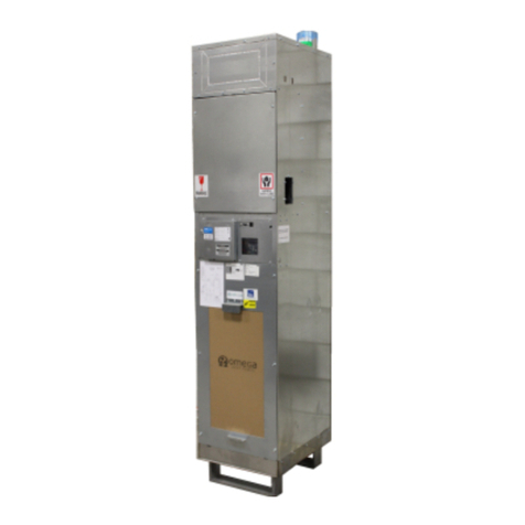
Omega VSHP SERIES User manual

OMEGA VSHP SERIES
Installation and Operation Manual (IOM)
VERTICAL STACKED
WATER SOURCE HEAT PUMPS
MODEL: VSHP SE / VSHP HE
FAN CABINET DEV. G
CHASSIS DEV.F, DEV.G
CONTROL BOARD: V3
DOCUMENT RELEASE: OMEGA-VSHP.G-IOM-2205
omega-heatpump.com
omega@omega-heatpump.com
Supersedes document OMEGA-VSHP.G-IOM-2203
Revision Notes:
-Chassis Storage & Inspecon
-Maintenance Schedule Update

OMEGA | WATER SOURCE HEAT PUMPS OMEGA-VSHP.G-IOM-2205
i
TABLE OF CONTENTS
1. General Information, Warnings and Disclaimer....................................................................................... 1
2. Cabinet Dimensions ............................................................................................................................... 2
3. General Unit Information ........................................................................................................................ 5
4. Inspection & Storage.............................................................................................................................. 5
Inspection of Unit........................................................................................................................ 5
Storage ...................................................................................................................................... 6
5. Cabinet & Riser Installation .................................................................................................................... 6
For Shipped Loose Riser Shut-Off Valves .................................................................................. 6
Cabinet Install ............................................................................................................................ 6
Riser Loop.................................................................................................................................. 7
Servicing .................................................................................................................... 7
Flushing & Cleaning ................................................................................................... 7
Riser System Loop Temperature................................................................................................ 7
Cooling Season .......................................................................................................... 7
Heating Season.......................................................................................................... 7
Operating Limits ......................................................................................................... 8
6. Chassis Installation ................................................................................................................................ 8
Installation of Fittings and Hoses................................................................................................ 8
Units with NPSM Riser and Chassis Fittings............................................................... 8
Units with NPT Riser and Chassis Fittings.................................................................. 8
Chassis Install............................................................................................................................ 8
7. Unit Start-Up ........................................................................................................................................ 10
Checklist .................................................................................................................................. 10
Initial Start-Up .......................................................................................................................... 10
8. Controls ............................................................................................................................................... 11
Microprocessor Controller ........................................................................................................ 11
DIP Switch Settings .................................................................................................. 11
Thermostat Cable..................................................................................................... 11
Fan Control with ECM............................................................................................... 11
Fan Speed Set by Thermostat .................................................................................. 11
Manual Fan Speed Control - 3-Speed Selector Switch ............................................. 11
Optional Whisper Mode - Fan Speed Set by Thermostat .......................................... 11
Sequence of Operation............................................................................................................. 12
9. Troubleshooting ................................................................................................................................... 12
Test Mode ................................................................................................................................ 13
Web Based Access .................................................................................................................. 13
10. Maintenance Guide ............................................................................................................................ 15
Replacement Filters ................................................................................................................. 15
Troubleshooting Guide ............................................................................................................................. 16
Start-Up Sheet ......................................................................................................................................... 36

OMEGA-VSHP.G-IOM-2205
1
IMPORTANT
READ THE FOLLOWING MANUAL PRIOR TO INSTALLATION, OPERATION and SER-
VICING THIS UNIT.
1. GENERAL INFORMATION & WARNINGS
SAFETY SYMBOLS – Warnings, Cautions & Notices
There are three advisory symbols used in this document to alert the reader:
Warning: Indicates a potentially dangerous situation which could result in death or
serious injury.
Caution: Indicates a possible hazardous situation which can result in possible inju-
ries or damage to unit and/or environmental pollution, or to alert against practices
that are unsafe.
Note: Identifies important information to the technician to complete the installation
correctly.
Responsible Refrigerant Practices
All technicians who handle refrigerants must be certified in accordance with local codes for
reclaiming, recovering, recycling and handling of refrigerants. Technicians must follow all
applicable local and federal laws.
Correct field wiring and grounding is required, failure to adhere and follow code
could result in death of serious injury. ALL FIELD WIRING MUST BE PER-
FORMED ONLY BY A QUALIFIED ELECTRICIAN. All wiring must be in accord-
ance of with the manufacturer’s specifications.
Wiring that is improperly installed and/or grounded could result in FIRE, ELECTRO-
CUTION, and other serious hazards. Manufacturer is not responsible for damage/
equipment or site issues resulting from the improper connections of the unit or the
use of improper controls.
Personal Protective Equipment (PPE) is mandatory. Technicians installing or ser-
vicing this unit must use all PPE including but not limited to: hard hats, safety glass-
es, cut resistant sleeves and gloves, electrical PPE, and fall protection.
Disclaimer
All units are certified and built in accordance to applicable government and industry stand-
ards. Any customer modifications performed without the express written approval from the
manufacturer are strictly prohibited and will void all warranties expressed or implied.
Modifications to the unit may result in hazardous or unexpected operation of the
unit. Modifications to the unit may result in a potentially hazardous situation result-
ing in equipment damage, property damage, injury or death.

OMEGA | WATER SOURCE HEAT PUMPS OMEGA-VSHP.G-IOM-2205
2
Notes:
• Temporary riser supports provided (Contractor to remove and install permanent riser clamps fastening risers to the
building structure).
• Return air opening is on the front of the unit.
• Discharge opening sizes are customer configurable. Published sizes shown are maximum factory default sizes.
Customer to verify discharge opening sizes match design requirements for proper airflow and select appropriate
discharge openings at time of order.
• Unit includes hose kits and manual shut off valves.
• Optional risers are furnished with type L, M copper. Available 3 inch deep swage connections on same size piping.
• Contractor to provide couplings where the piping is not swaged or for joining dissimilar piping sizes.
2. CABINET DIMENSIONS
VSHP Cabinet Dimensions (Silver & Gold Series) - Standard & High Efficiency
"W" "D" "C" Horizontal Top
VSHP 020G 14 x 8 12 x 12
VSHP 030G 14 x 8 12 x 12
VSHP 040G 14 x 10 12 x 12
VSHP 050G 16 x 12 14 x 12
VSHP 060G 16 x 12 14 x 12
VSHP 080G 18 x 14 14 x 14
VSHP 100G 18 x 16 16 x 14
VSHP 120G 18 x 16 16 x 16
Dimensions (in)
VSHP Supply Discharge Opening
(W X H) inches
14
16
20
Y
18
20.5
Z
22
24.5
Model
Cabinet
Size
X
16
17.5
VSHP - Silver Series Dimensions

OMEGA-VSHP.G-IOM-2205
3
VSHP - Gold Series Dimensions

OMEGA | WATER SOURCE HEAT PUMPS OMEGA-VSHP.G-IOM-2205
4
VSHP Assembly View (Silver Series Cabinet)
1. Supply, return and condensate risers. Type ‘M’ or ‘L’ copper.
2. Field “knockout” supply air openings (Front/Back/Side/Top)
with 1-1/2” duct ange.
3. Electrical box with advanced microprocessor.
4. (Oponal) 1.5-inch perimeter ange
5. Removable Blower / Fan assembly
6. Heat pump chassis (HE chassis shown)
7. Chassis service cover panel.
8. 1-inch MERV 8 pleated air lter.
9. Return air (R/A) panel available in acousc or perimeter
(Acousc shown).
1
2
3
4
6
7
5
8
9

OMEGA-VSHP.G-IOM-2205
5
3. GENERAL UNIT INFORMATION
BLOWER & MOTOR
The unit comes with a blower and motor assembly that
is mounted to a blower deck inside the unit cabinet, lo-
cated above the chassis behind the electrical box. Re-
moval of the blower/motor assembly is done through the
chassis compartment opening.
UNIT NAMEPLATES
The nameplate contains information about the unit in-
cluding model and serial numbers, electrical data and
refrigerant charge information. The cabinet nameplate is
located on the surface of the cabinet and the chassis
nameplate is located on the chassis. Collecting the in-
formation on the nameplate will be useful when contact-
ing your local customer service representative or when
ordering parts. Size wiring and circuit breakers to
nameplate rating identified on the unit.
CONTROLS
The unit comes with a factory supplied transformer. See
wiring diagram for field wiring a thermostat to the electri-
cal box low voltage terminals. High voltage connection is
made on the left side of the cabinet and low voltage con-
nections enter through the right side of the cabinet.
MICROPROCESSOR CONTROLLER
Unit comes with a microprocessor controller that moni-
tors the entire function of the unit. The microprocessor
board comes with an integral terminal strip for wiring
thermostat cable.
REFRIGERANT CONNECTIONS
Low and high pressure side refrigeration service ports re
located inside the compressor enclosure. Slide out chas-
sis and remove sheet metal enclosure to access fittings.
CABINET– SILVER SERIES
The standard Silver series cabinet is a fully factory as-
sembled one piece cabinet. Use flexible duct connec-
tions for connecting cabinet to supply ducts to prevent
vibration and noise transmission into occupant space.
Discharge openings should be sized to meet site design
conditions. Factory default sizes shown are maximum
allowable size.
CABINET– OPTIONAL GOLD SERIES
The optional Gold series cabinet comes in two sections
for isolating fan cabinet from ductwork. The upper sec-
tion discharge plenum is lined with 1” thick insulation on
all inside surfaces. Plenum is secured to cabinet with
shipping brackets. Once discharge plenum is fastened to
the underside of the concrete slab shipping brackets
must be removed. Factory installed flexible connection
joins the upper and lower sections. “S” and “D” cleats
are used to join upper and lower plenums to the metal
portion of the flex connection. The plenum comes with
factory pre-punched knockouts on all sides. Discharge
openings should be sized to meet site design conditions.
Factory default sizes shown are maximum allowable
size.
RETURN AIR PANEL—ACOUSTIC & PERIMETER
The Acoustic Return Air Panel is insulated with 1/2”
thick, acoustic insulation and removable without tools to
allow access to the filter, service disconnect switch, all
electrical controls and chassis. The panel is removed by
swinging out and lifting it off the support pegs. The pan-
el should be flush mounted to the drywall as per installa-
tion guidelines.
The Perimeter Return Air Panel door is a hinged door
panel mounted in the drywall opening and fastened to
the wall studs.
Cabinet base height and maximum baseboard height
dimensions can be determined by referenc-
ing the Return Air Panel Installation sections.
Use appropriate example based on Return
Air Panel type ordered.
THERMOSTAT
A field provided thermostat cable is required to connect
to the control board terminal blocks. A minimum 4-wire
thermostat cable is required for use with basic thermo-
stats that do not require a ‘Common’ wire. A min. 5-wire
is recommended.
4. INSPECTION & STORAGE
INSPECTION OF UNIT
Prior to the installation of the unit perform the following
checks:
• Visually inspect the packaging, cabinet and chassis
for signs of shipping damage prior to signing the bill
of lading. Check that the units match the sales order
by referring to the cabinet labels, and chassis
nameplate information.
• Inspect the riser ends and stub-outs for any sign of
damage.
• Verify breaker and power supply meet electrical
nameplate requirements of the unit.
• Check that the nameplate of the units matches the
floor plan layout.
When construction is not complete including concrete
core drilling, drywalling, plastering, painting or any work
that would contaminate the storage space all necessary
precautions are to be taken to prevent the cabinet and
chassis from becoming contaminated. Particulate infil-

OMEGA | WATER SOURCE HEAT PUMPS OMEGA-VSHP.G-IOM-2205
6
tration (i.e. drywall dust) into cabinet and chassis coil
could result in equipment damage. Fumes could result
in premature corrosion (formicary corrosion) of the chas-
sis air-coil resulting in refrigeration system leaks.
STORAGE
Both cabinet and chassis units are designed for indoor
use only. Care must be taken to protect the unit from
environmental damage. Store the chassis in an environ-
ment with a temperature above (32oF). To prevent con-
tamination the units should be stored indoors. For tem-
porary outdoor storage ensure:
• Units should be placed in an area that will not be
exposed to any moisture. Units should be placed on
a dry and raised surface. Do not stack units.
• Cover the units with a waterproof tarp.
• Failure to keep the units dry could result in the inte-
rior insulation becoming wet and cause the growth
of mold.
• Chassis units must be stored in the upright position
to keep oil in the compressor.
• Chassis water openings and Riser ends should be
capped if being stored on site to prevent contamina-
tion from foreign objects and debris.
Chassis water circuit must not be filled
with any untreated or standing water prior
to full commissioning otherwise equipment
damage may occur.
Do not store cabinets on their side when chas-
sis units are inside. Chassis units should al-
ways be stored and transported in the upright
position otherwise damage to chassis may
occur.
The refrigeration system of these units con-
tains POE oil. PVC/CPVC piping is prone to
failure when in contact with POE oil. PVC/
CPVC piping should not be used for water
supply, return or condensate risers with any
heat pump products as this may result in failure
of the system and serious property damage.
Do not rest or lean the unit on the risers.
Do not use the risers or stub-outs to pick
up the unit. Only designated lift points
should be used when moving or lifting cab-
inets. Do not drop the risers.
5. CABINET & RISER INSTALLATION
Risers are designed to have slight adjustments
for riser system expansion and aligning the
stub-outs in the cabinet opening. When in-
stalling risers, do not let riser stubs bottom out
in the riser swage.
Risers are designed to allow for 1-1/2 inches of
movement due expansion and contraction. If
the total calculated riser expansion exceeds ±1
-1/2 inches the field must provide expansion
compensators.
Riser stub-outs should be located as centrally
as possible in the cabinet opening. Do not
allow stub-outs to rest or contact the sheet
metal opening.
Do not allow the risers to bottom out when
installing into the swage.
FOR SHIPPED LOOSE RISER SHUT-OFF VALVES
Visually inspect riser stub-outs and shut-off valves for
debris or damage.
Follow industry standard soldering practices
when soldering shut-off valves to riser stub-
outs.
Ensure riser stub-out surface is cleaned of any
residue, soot or oils. Failure to adequately
clean soldering surfaces can result in water
leaks, property damage and physical injury.
When soldering shut-off valves to riser stub
outs, adequately protect cabinet, insulation
and any other equipment from exposure to
flames and heat.
CABINET INSTALL
1) When cabinets are shipped with risers attached, place
cabinets in a horizontal position on the floor (do not rest
cabinet on the risers).
2) If required, install any field or factory supplied riser
extensions to the unit mounted risers.

OMEGA-VSHP.G-IOM-2205
7
3) Raise the entire cabinet slowly upright while at the
same time lowering the risers through the floor cut-out
opening. Align the risers to the matching swaged section
of the riser on the floor below.
4) Swaged sections are approximately 3 inches deep.
Risers should be inserted at a depth of approximately 2
inches into the 3 inch deep swage. Confirm risers pene-
trate at a minimum of 1 inch into the swage. Do not allow
the riser tailpiece to bottom out fully into the 3 inch deep
swage. This will allow for floor to floor variations, other-
wise riser overlap may not be sufficient on upper floors.
5) Align and center riser positions in the pipe chase and
level cabinet as necessary.
6) Secure the cabinet to the floor. Cabinet base comes
with factory mounted neoprene pads.
7) Center the riser stub-outs in the cabinet openings to
allow for riser expansion and prevent contact with cabi-
net sheet metal. Prevent riser stub-outs from contacting
sheet metal pass through otherwise damage to stub-
outs may occur, resulting in serious water damage.
8) Secure risers to building structure as per engineering
design specifications. Do not allow the risers to be sup-
ported by the cabinets. Field supplied riser compensa-
tors are required if the temperature range of the system
exceeds the expansion and contraction limit.
9) Using industry accepted soldering and brazing stand-
ards and materials to solder or braze the riser joints.
10) Connect supply ducts and discharge grilles.
11) Connect to optional Fresh Outside Air Duct (Snorkel)
when connecting to remote ERV.
RISER LOOP
Do not connect chassis to the water circulat-
ing system when flushing is being conducted
to prevent debris and fouling of the water side
components of the chassis (i.e. auto balanc-
ing valve, auto shut-off valve, coaxial coil).
Do not flush and clean riser system with chas-
sis units connected. Do not allow the flushing
and cleansing solutions to flow in the chassis
water coil. Damage to water components
may occur.
Do not let untreated, standing and/or stag-
nant water sit inside chassis. Connect
chassis water connections by opening
isolation valves only when riser system is
treated and flowing.
Servicing
To enable system flushing, servicing and balancing of
supply and return risers the following field supplied com-
ponents are required: shut-off valves, drain tees and
drain valves, and flow measuring devices. Refer to the
job site engineering design specifications and building
drawings for more detailed information.
Flushing & Cleaning
Once the riser system is complete the riser system must
be cleaned and flushed, refilled and chemically treated
with industry accepted inhibitors. Untreated riser loop
water will result in premature wear and potential failure
of system components due to water coil leaks inside
chassis. Filters must be installed in riser loop system
and checked, cleaned as per regular maintenance
schedule.
Supply and return pipes must be interconnected, at a
minimum in the top and bottom units of each riser, with
factory supplied hoses to properly flush system and en-
sure adequate elimination of foreign material and clean-
ing of riser system.
1) Use only clean water to fill water circulation system.
Fill the water circulating system at the municipal water
makeup connection with all air vents opened.
2) After air vents have been sequentially closed and
riser system is primed begin water circulation of the sys-
tem to purge remaining trapped air bubbles.
3) Shut off the circulating pump and open all the drains
and vents to completely drain the system.
4) The riser system should be cleaned after the initial
flush and flushed a second time to adequately rinse the
riser system of cleaning solution.
5) Riser system is then re-filled with clean city water and
chemically treated to inhibit corrosion, oxidization and
fouling of the riser loop system. Do not use untreated
water to run heat pump chassis units.
Chassis installation is permitted only once the riser
system is thoroughly flushed, cleaned, and commis-
sioned by the riser treatment company and contrac-
tor.
RISER SYSTEM LOOP TEMPERATURE
Correct riser system loop temperature settings are im-
portant for optimal unit operation. Temperatures outside
of the recommended range will affect overall unit operat-
ing performance (capacity and efficiency), long term
reliability and sound performance.
Cooling Season
In cooling mode recommended riser loop temperatures
should be maintained between 85oF to 90oF. Higher riser
loop temperatures reduce unit cooling capacity and effi-
ciency. Lower riser loop temperatures will increase unit

OMEGA | WATER SOURCE HEAT PUMPS OMEGA-VSHP.G-IOM-2205
8
operating efficiency.
Operation of riser loop temperatures above 110oF EWT
is not permitted. Elevated risers loop temperatures may
cause nuisance alarm trips. Refer to ‘Unit Operation
Limits”.
Heating Season
In heating mode riser loop temperatures must be main-
tained within 55oF to 90oF for standard range operation.
For Low Temperature Water (LTW) operation, riser loop
temperature are permitted down to 45oF EWT with water
only lopp systems. In Geothermal Range operation, be-
low 45oF EWT, the system loop must contain an appro-
priate glycol mixture for loop systems to protect the sys-
tem from freezing the water circuit. For Geothermal op-
eration units must come with factory Geothermal Range
option. Do not operate riser system below 20oF EWT.
Operating Limits
Design limits can not be combined. Combin-
ing maximum or minimum limits is not al-
lowed. This could exceed the operation and
design limits of the unit.
For example: It is not allowed to combine
maximum entering air temperature (EAT) limits with
maximum entering fluid temperature (EFT) limits.
6. CHASSIS INSTALLATION
Do not apply plumbers putty, pipe dope or
sealing tape to NPSM water fittings.
Always use a back-up wrench when tightening
hoses or fittings. Damage to copper pipes and
solder joints could result in serious equipment
and property damage.
Check hoses and fittings for any visible dam-
age or debris.
Remove the chassis top cover panel and inspect the
inside of the chassis unit. Ensure that the water and
refrigerant tubing is free from obvious physical damage
and kinks.
Check that piping does not touch other unit
components and other piping. Internal cop-
per pipes can shift during transport, storage
or installation.
INSTALLATION OF FITTINGS AND HOSES
Upon removal of service cover panel check cabinet inte-
rior for construction debris and dust. Clean out all dust
and debris.
Units with NPSM Riser and Chassis Fittings
Connect the supplied hoses to the Male-NPSM riser
shut-off valves. Do not apply pipe dope or pipe sealant
to NPSM fittings. Always use a back-up wrench. Fin-
ger tighten hose and tighten with back-up wrench
approximately 1/6 turn. DO NOT OVERTIGHTEN.
Units with NPT Riser and Chassis Fittings
Connect the supplied male-male (NPT/ NPSM) cou-
plings to the Female-NPT supply and return riser shut-
off valves.
Do not apply pipe dope to the NPSM fit-
tings, as these are flare style fittings.
Connect the supplied hoses to the riser shut-off valves.
Always use a back-up wrench. DO NOT OVERTIGHT-
EN.
Step by step instructions when connecting hoses to iso-
lation valves:
1) Do not use pipe dope or Teflon tape! Hand
tighten hose to the isolation valve.
2) Use back-up wrench located at the front of the
valve or secure to the middle of the valve
body. Tighten a further 1/6 turn. Approx. 20FT/
LBS of torque.
Heating
DB WB DB
Std. Entering Air Temperature (EAT) 75oF63oF68oF
Min. Entering Air Temperature (EAT) 65oF55oF50oF
Max. Entering Air Temperature (EAT) 85oF71oF80oF
Cooling Heating Cooling Heating Cooling Heating
Std. Entering Fluid Temperature (EFT) 85oF70oF85oF55oF85oF60oF
Min. Entering Fluid Temperature (EFT) 50oF55oF50oF45oF30oF20oF
Max. Entering Fluid Temperature (EFT) 110oF90oF110oF90oF110oF90oF
Cooling
Air Limits
Standard Range
Low Temp Water Range
Fluid Limits
Geothermal Range
Min. CFM/Ton 300 Min. GPM/Ton 1.5
Design CFM/Ton 400 Design GPM/Ton 3
Max. CFM/Ton 450 Max. GPM/Ton 4
Fluid GPM Limits
CFM Limits

OMEGA-VSHP.G-IOM-2205
9
3) Do not use back-up wrench on the back-side
of the valve as this may place undue stress on
valve body construction.
4) Correct and incorrect areas where to place
back-up wrench are shown with two common
valve types.
CHASSIS INSTALL
1. Leave cardboard shipping cover on the air coil cov-
er in place. Check chassis nameplate to verify
chassis model matches cabinet model for compati-
bility.
2. If not already done so, remove top cover and check
that no water and refrigeration piping are touching
other tubes or parts.
3. Align chassis with front of the cabinet and tilt chas-
sis so that the back aligns with the cabinet rails.
4. Slide chassis into cabinet partially. Check to ensure
wiring harnesses are not being pinched. Adjust the
chassis to ensure it is resting approximately cen-
tered in the rails.
5. Connect the hoses by hand to the chassis supply
and return connections. Hand tighten, then using a
back-up wrench tighten fittings as necessary. En-
sure that the hose supply and return connections
are not reversed and matched to correct risers. Wa-
ter IN and water OUT is stamped on the chassis
sheet metal enclosure.
6. If riser loop system has been commissioned and
operational open the riser shut-off valves. Check for
any signs of water leaks at all water connection
points.
7. Connect the chassis electrical plugs to the quick
connect mating plugs in the cabinet electrical box.
8. Slide the chassis into the cabinet. Check to ensure
wiring harnesses and hoses are not being pinched.
Do not push against the air coil surface.
9. Ensure hoses are not pressed against unit cabinet.
10. Remove cardboard shipping cover from the air coil.
11. Install the service cover panel and visually check
foam gasket around service cover panel perimeter
is not damaged and providing an adequate seal.
12. Insert filter into service cover panel.
13. Install Return Air Panel into the closet drywall open-
ing if not already done and secure with screws.
INCORRECT AREA
X
CORRECT AREA
X

OMEGA | WATER SOURCE HEAT PUMPS OMEGA-VSHP.G-IOM-2205
10
7. UNIT START-UP
Ensure the building loop system has been cleaned,
flushed, chemically treated and commissioned by the
water treatment company. Verify that the main system
strainers or mechanical filtration system has been in-
stalled and commissioned. The chassis should be at
room temperature (68oF) prior to start up.
Once the riser loop system is commissioned the riser
shut-off valves can be opened. Water flow failure will
cause the unit to trip on the safety devices. Repeated
water flow failures can cause equipment damage.
BATTERY CLOCK
An optional battery can be installed in the controller to
preserve the current clock. Upon power loss the time will
be maintained. Without a battery the date and time will
reset.
CHECKLIST
Before energizing the unit ensure all steps are verified in
the following checklist:
___High voltage power supply is correct and in accord-
ance with unit nameplate ratings.
___Unit is electrically grounded and circuit protection is
the correct size.
___Low voltage control wiring is per unit wiring diagram.
___Riser loop system is clean, filled, and vented of air.
___Chassis unit high and low pressure caps are firmly
secure and in place.
___Chassis matches the cabinet model number.
___Protective cardboard coil cover is removed and unit
service cover panel and a clean air filter are in place.
___There is a proper seal between chassis service cov-
er panel and unit cabinet.
___Riser shut-off valves are in the OPEN position.
___Riser loop water is circulating through all units and at
design conditions.
___Unit condensate drain hose is securely attached to
drain pan and condensate riser.
___Indoor unit blower spins freely.
___All ductwork is complete.
___All cutting, sanding, drywalling, patching work is
complete.
___Thermostat is in the OFF position.
INITIAL UNIT START-UP
1. Close disconnect switch.
2. Set thermostat to a high setting (above current room
temperature), set system to COOL with fan on AU-
TO. The compressor should not run.
3. Lower the thermostat temperature setting until the
fan and compressor energize. Verify the following
results:
• Leaving water temperature (LWT) in the heat ex-
changer water coil is warmer than the entering wa-
ter temperature (EWT) by approximately 9oF—12oF.
• Blower is running smoothly.
• Compressor and blower amps are within nameplate
data.
• Suction line is cool and no frosting is forming in the
refrigeration circuit.
4. Set thermostat to the OFF position. Unit compressor
and fan should stop running.
5. Allow the system to equalize for approximately 5
minutes.
6. Set thermostat to the lowest setting and switch to
the HEAT position.
7. Adjust thermostat temperature higher until the fan
and compressor energize. The following should
occur:
• Warm air will flow from the supply register.
• Leaving water temperature (LWT) in the heat ex-
changer water coil is cooler than the entering water
temperature (EWT) by approximately 5oF—9oF.
• Blower and compressor operation is smooth and no
frost development is visible in the refrigeration cir-
cuit.
8. Set the thermostat to the desired temperature.
9. Check for any water leaks at the hose connections.

OMEGA-VSHP.G-IOM-2205
11
8. CONTROLS
MICROPROCESSOR CONTROLLER
DIP Switch Settings (BLU Board Only)
Controller DIP switch contains 10 switches for setting up
thermostat, Fan, and system settings. Microprocessor
DIP settings are factory set. Make changes if warranted
by site conditions. Below are the 10 settings:
DIP 1= Set thermostat type used. Default is HeatPump
DIP 2 = Hybrid or Heat Pump Unit
DIP 3= Variable Flow (Control Valve Powered on Call for Com-
pressor; Constant Flow (Control Valve Always Powered to
Open Position)
DIP 4= Control Valve NO or NC (NC is default)
DIP 5= Reversing Energized to Heating or Cooling (Energized
to Cooling is default)
DIP 6= Fan speed control: 3-Speed slider switch (OFF/Manual);
or Thermostat (ON/Auto).
DIP 7= Condensate Overflow Switch - Enabled or Disabled.
DIP 8= Condensate Type switch used. Normally Open or Close.
Factory default is NO.
DIP 9= Spare. Not used unless custom configured.
DIP 10= ON or OFF monitoring of EWT & LWT sensors for
alarms. Factory default is OFF.
Heat Pump Thermostat
When using Heat Pump Thermostat (recommended
setting) set DIP #1 to the “ON” position. See table below
for connecting thermostat to unit terminal blocks:
When setting thermostat to HEAT PUMP mode check
the following:
“G” Terminal Close (24V) = call for fan
“Y” Terminal Closed (24V) = call for compressor
Heating: “O/B” (0V) = Reversing Valve De-Energized
Cooling: “O/B” (24V) = Reversing Valve Energized
Heat/Cool Thermostat - Requires Power to G (Fan)
Ensure thermostat provides 24V power to G (fan) termi-
nal during call for heating or cooling. When using HEAT/
COOL thermostat set DIP #1 set to the “OFF” position.
See table below for connecting thermostat to unit termi-
nal blocks:
Thermostat Cable
Field wire thermostat cable pigtail to the control board
terminal blocks. A minimum 4-wire thermostat cable is
required for single fan speed thermostats where com-
mon wire is not required. A 5-wire cable is recommend-
ed for most modern thermostats.
Ensure thermostat provides 24V power to G (fan) termi-
nal during call for heating or cooling.
Fan Control with EC Motors (ECM)
Pulse Width Modulated (PWM) signal is utilized to con-
trol fan motor speeds between 0 and 100% of full speed.
The controller has been programmed to use 3 pre-
programmed speeds for Low, Medium and High. With
optional Whisper Mode when there is a no request for
cooling or heating, unit will operate in ‘Whisper Mode’ for
ultra low fan speed air circulation.
Fan Speed Set by Thermostat
Wire thermostat wire to required fan speed terminal and
set DIP Switch #6 on the board to (ON) Auto. Fan speed
will be determined by wiring to the G1,G2, or G3 termi-
nals:
G1 Signal = LOW fan speed enabled.
DIP 1 (ON) = HeatPump Thermostat
TERMINAL
BLOCK
WIRE DESCRIPTION
TB1 #4 R 24VAC – Line (R)
TB1 #3 G1 Fan Speed 1 - Low Speed
TB1 #2 G2 Fan Speed 2 - Medium Speed
TB1 #1 G3 Fan Speed 3 - High Speed
TB2 #3 Y Call for Compressor
TB2 #2 O/B Call for Reversing Valve
TB2 #1 C Common (Optional)
DIP 1 (OFF) = HEAT/COOL Thermostat
TERMINAL
BLOCK
WIRE DESCRIPTION
TB1-4 R 24VAC – Line – (R)
TB1-3 G1 Fan Speed 1 - Low Speed
TB1-2 G2 Fan Speed 2 - Medium Speed
TB1-1 G3 Fan Speed 3 - High Speed
TB2-3 Y Call for Cooling
TB2-2 O/B Call for Heating
TB2-1 C Common (Optional)
DIP DESCRIPTION OFF ON
1Tstat Type Heat/Cool Tstat HeatPump Tstat
2HP Type Hybrid HP Std Heat Pump
3FlowType Variable Flow Constant Flow
4Coax Valve Coax Valve NO Coax Valve NC
5
Reversing Valve
(RV)
RV Energized to Heat RV Energized to Cool
6FanMode Fan Manual Fan Auto
7
Condendate
Overflow
Enabled Disabled
8COS Type NC1NO2
9Spare 1 Empty Empty
10 Spare 2 Sensors Off Sensors ON
NO = Normally Open and NC = Normall Closed
1) Condensate Alarm on Open - 2-wire Float Switch
2) Condensate Alarm on Close - 1-wire Electronic Switch

OMEGA | WATER SOURCE HEAT PUMPS OMEGA-VSHP.G-IOM-2205
12
G2 Signal = MEDIUM fan speed enabled.
G3 Signal = HIGH fan speed enabled.
Manual Fan Speed Control - 3-Speed Selector
Switch
Enable the unit mounted 3-speed selector switch by
setting DIP Switch #6 to OFF (Manual). Run fan wire
from thermostat to any of the G1, G2, G3 terminals. Fan
speed will be determined by the position of the unit
mounted 3-speed fan selector switch:
L = LOW fan speed
M = MEDIUM fan speed
H = HIGH fan speed
(not available with Whisper Mode)
Optional Whisper Mode
Optional Whisper Mode is factory enabled.
SEQUENCE OF OPERATION
Call for Heating and Cooling
When a compressor request is made, the optional mo-
torized auto shut-off control valve will open. The com-
pressor contactor will then be energized so long as none
of the following fault conditions are present:
• High-Pressure Alarm
• Low-Pressure Alarm
• (Optional) High-Pressure Water Alarm
• (Optional) Condensate Over Flow Alarm
• Compressor Anti-Short Cycle 7 min. timer expired
• (Optional) Entering Water Temperature (EWT) is
greater than 115oF
• (Optional) Leaving Water Temperature (LWT) great-
er than 127oF
When call for compressor request is terminated, the
optional motorized auto shut-off control valve and the
blower fan will remain open until the timers have ex-
pired.
Low-Pressure Bypass
During a call for compressor, the low-pressure switch is
bypassed for the first 3 minutes of compressor operation
to prevent nuisance low-pressure start-ups.
Timers and Interlocks
Microprocessor board utilizes a number of timers and
interlocks in the control sequence of the unit.
Anti-Short Cycle Timer
The compressor anti-short cycle timer of 7 minutes
starts every time a call for compressor is terminated to
prevent compressor over cycling.
Fan-On/Off Timer
The Fan-On timer of 10 seconds starts anytime there is
a call for fan request and 10 seconds after a call for
compressor is terminated.
Valve Open/Closed Timer
The valve open timer of 1 minute starts anytime a fan
and compressor request are made to develop flow in the
water coil. The valve closed timer of 1 minute starts any-
time a call for compressor is terminated to allow for
flushing of the water coil.
Random Wait Time on Unit Power Up
Microprocessor controller uses a random wait time dur-
ing unit start up between 1-30 seconds.
9. TROUBLESHOOTING
Refer to the ‘Troubleshooting Guide’ for identifying com-
mon issues and possible resolutions. The microproces-
sor control board has a number of LED lights for simple
identification of common alarms and faults. Refer to
’LED Code Table Guide’.
TEST MODE
A Test mode feature can be enabled in order to perform
diagnostic testing of the unit by reducing all timers.
To enable test mode press the test mode button on the
control board.
CLOCK SETTING
Using the webpage tool the internal date and time of the
controller can be set to assist with diagnostics when
using the data log. An optional battery will preserve date
and time in the event of a power loss.
WEB PAGE ACCESS
The Omega controller features a webpage configuration
and troubleshooting tool. Unit status and diagnostics
temperature (Supply Air, Entering Water, Leaving Water
and Suction Temperature) readings can be easily ac-
cessed through the controller webpage tool.
The imbedded webpage is accessed by connecting to
the control board, no internet connection required. There
are two ways to connect: using a mini-wireless router or
directly to a laptop. Wireless router is the preferred
method for fewer configuration steps and works with
Tablets or Smartphones.

OMEGA-VSHP.G-IOM-2205
13
Wireless Router Method
1. To connect to the controller you will need the follow-
ing: Ethernet cable, Laptop/Tablet, and wireless
router (e.g. TP Link TL-WR802N, shown below).
Configure routers as per manufacturer instructions.
Setup as Access point with Static IP (leave IP ad-
dress blank).
2. Remove electrical box access panel and connect rout-
er via ethernet cable directly into surface mounted ether-
net port (RJ45) on control board.
3. Connect tablet, laptop or phone to WIFI router. Turn
off mobile data. Once connected open up your internet
browser (i.e. Internet Explorer, Google Chrome) and
type in the following address 192.168.0.99
Direct to Laptop Method
1. To connect to the controller with a laptop you will need
the following: Ethernet cable & Laptop.
2. Remove electrical box access panel and connect
ethernet cable directly into surface mounted ethernet
port (RJ45) on control board.
3. On laptop access “Network and Sharing Center“
though the “Network & Internet Settings” icon located in
the bottom right taskbar.
4. In the Network & Sharing Center click on “Ethernet” /
“Local Area Connection” as indicated below.
5. Local Area Connection Status will open, click on Prop-

OMEGA | WATER SOURCE HEAT PUMPS OMEGA-VSHP.G-IOM-2205
14
erties, then click on “Internet Protocol Version 4 (TCP/
IPv4)”, and click on Properties for IPv4.
6. With Internet Protocol Version 4 (TCP/IPv4) window
open click on “Use the Following IP Address” and
change the IP address to 192.168.0.100 and Subnet
mask to 255.255.255.0, as shown below. Then click
“OK”.
7. Open up your internet browser (i.e. Internet Explorer,
Google Chrome) and type in the following address
192.168.0.99.
8. The following home page will load for the controller
software. Below is a screen shot of the interface (version
5.4.1 software is shown).
9. An event log feature called ‘Log Dump’ allows for re-
cording unit operation information during faults or at start
-up as a troubleshooting aid. For example in the figure
below the first line item indicates “Y” terminal was ener-
gized (Y=1) when the Cooling (CLG=1) and tripped on
Low Pressure fault (LP=0).
Captured unit controller details include: ‘Y’ ,’O/B’, ‘CPR’
=compressor, ‘RV’= reversing valve, ‘HTG’ = heating,
‘CLG’ = cooling, LP = low pressure, ‘HP’ = high pres-

OMEGA-VSHP.G-IOM-2205
15
10. MAINTENANCE GUIDE
Proper unit maintenance will result in optimal unit perfor-
mance and prevent potentially costly repairs or property
damage. Turn unit disconnect switch to off and turn unit
off at circuit breaker/fuse panel before starting mainte-
nance procedure.
Do not operate unit without filters or during
any temporary construction that could clog the
air filter or air coil.
Do not use any cleaning solutions that contain
acids on the air-refrigerant coil or any refriger-
ant components.
30 DAY MAINTENANCE
1. Visually inspect filter monthly for dirt and clogging.
Replace as required with a quality filter.
2. Vacuum dust from unit air grilles and surrounding
coil area with soft bristle brush attachment as re-
quired.
3. Every month visually inspect unit for any signs of
water leaks, or water damage around floor or sur-
rounding drywall.
3 MONTH MAINTENANCE
1. Inspect condensate drain every 3 months for signs
of stagnant water, microbial growth, and mineral
buildup. Clean drain pan with an appropriate clean-
ing solution as required to prevent condensate hose
blockages and microbial growth.
2. Check valves and hoses for signs of leaks, cracking
or deterioration.
6 MONTH MAINTENANCE
1. Check condensate flow to ensure adequate drain-
age and test for signs of impending blockages.
2. Check that condensate alarm is operating correctly
if installed.
3. Visually inspect the air coil for signs of dirt accumu-
lation. Use a mild approved coil-cleaning agent. DO
NOT use any cleaning solutions that contain an
acid, including acetic acid (vinegar). Damage to the
air coil may occur resulting in possible refrigerant
leaks.
ANNUAL MAINTENANCE
1. Perform an annual maintenance inspection of the
fan and blower motor assembly. All units come with
permanently lubricated fan motors. DO NOT oil or
lubricate fan motors. Clean up any dirt or debris that
may have accumulated.
2. Visually inspect the electrical box annually for signs
of component damage due to overheating or poor
electrical contact.
3. Completely clean the interior of the cabinet. Vacu-
um any dust or debris.
5-7 YEAR MAINTENANCE
1. Replace compressor capacitor.
2. Replace compressor power relay.
REPLACEMENT FILTERS & CRITICAL CHARGE
Disposable 1-inch thick replacement filters, sizes listed
below and can be obtained from most HVAC parts sup-
pliers.
Factory also provides optional 2-inch filter rack for use
with 2-inch MERV 13 filters.
Factory provided 1-inch filters are MERV 8/10. Pleated
filters rated between MERV 8 to MERV 11 are prefera-
ble as they will provide balance between filtration and
airflow. Higher rated filters (MERV 12, 13+) may reduce
airflow and require frequent replacement. Factory rec-
ommends optional 2-inch filter rack when using MERV
13 filters.
Units are critically charged with refrigerant and ap-
plying pressure gauges to unit may cause unit to
lose some charge. Follow best practices and ex-
haust reasonable troubleshooting steps before ap-
plying gauges to unit.
VSHP 020
VSHP 030
VSHP 040
VSHP 050
VSHP 060
VSHP 080
VSHP 100
VSHP 120
Standard Efficiency (SE)
Model
Cabinet
Size
X
14 x 25 x 1
Standard 1-inch
Filter Size
Optional 2-inch
Filter Size
14 x 25 x 2
16 x 25 x 2
20 x 25 x 2
Y
16 x 25 x 1
Z
20 x 25 x 1
VSHP 020G
VSHP 030G
VSHP 040G
VSHP 050G
VSHP 060G
VSHP 080G
VSHP 100G
VSHP 120G
High Efficiency (HE)
Model
Cabinet
Size
Standard 1-inch
Filter Size
Optional 2-inch
Filter Size
X
14 x 25 x 1
14 x 25 x 2
Y
16 x 30 x 1
16 x 30 x 2
Z
20 x 30 x 1
20 x 30 x 2

OMEGA | WATER SOURCE HEAT PUMPS OMEGA-VSHP.G-IOM-2205
16
Troubleshooting Guide
Problem Mode Time To
Trip Possible Cause(s)
Likelyhood to
occur
Correction Method
Heating/Cooling Main power off Med Check unit circuit breaker.
Heating/Cooling
Blown transformer / Blown
Low Voltage Fuse
High
3 Amp fuse pops usually when there is a short to ground. Check thermostat wiring, control wiring,
and verfiy wiring in chassis has no short to ground.
Heating/Cooling
Blown transformer / Blown
Low Voltage Fuse
High
Short to ground inside chassis. Open top cover of chassis cover, check for shorts, signs of arcing,
loose connectors and worn shielding especially near refrigerant piping.
Heating/Cooling
Blown transformer / Blown
Low Voltage Fuse
High
Confirm there is no short to ground before replacing transformer. Built in 3A fuse is designed to
protect transformer. If no short to ground found, replace transformer.
Heating/Cooling Broken or loose connection High
Check for loose thermostat connections at the control board and at thermostat base. Repair and/or
tighten as required.
Heating/Cooling Damaged thermostat cable Low Check for damaged wires on the thermostat cable
Heating/Cooling Defective thermostat Med Check and replace
Unit short cycles Heating/Cooling Thermostat improperly located Low Relocate thermostat away from supply registers.
Breaker Trip Heating/Cooling 0min
Short to ground on high
voltage side
Low
Isolate main components: disconnect chassis harnesses and fan harness from electrical box. Check
by turning on breaker and then disconnect. If Breaker trips again, the short to ground inside the
electrical box. Using ohm meter check for short to ground inside electrical (check for loose wires, or
damaged wire shielding). Otherwise short to ground is located inside the chassis or at the fan motor.
Heating/Cooling 0min Tripped Circuit Breaker Low
Disconnect chassis power harness only. Power up unit. If breaker trips only when chassis is
connected, check chassis power wiring for a potnential locked rotor. Compare current reading
(Amps) to nameplate.
Heating/Cooling Burnt out compressor
overload High
Check and replace if required. Located on top of Rotary compressor. Remove plastic cap, check
resistance (size 020-060 units only).
Heating/Cooling
Defective compressor
contactor
Low
Check 24VAC coil on contactor is getting power. If powered but coil does not close line voltage
contacts or stays open/close replace contractor. Replace every 5-7 years.
Heating/Cooling Supply voltage too low Low
Correct incoming supply voltage setting at Transformer. Check that the line voltage is matched to
208V or 240V transformer taps
Heating/Cooling
Defective compressor
capacitor
Med Check capacitor and replace if required. Should be replaced every 4-5 years.
Heating/Cooling
Defective compressor
windings
Low Check compressor windings for damage. Replace if required
Heating/Cooling 0 - 3min Limit switches open
Check for faulty pressure switches. Switches are normally closed. Check for bad connections at wire
terminals. Replace if switches are open when unit is shutdown and there are no wire connections
issues.
Heating/Cooling 0min
Clogged Drain Pan /
Condensate hose / Faulty
Sensor
Condensate switch detects overflow condition in drain pan, check for obstruction. If no water is
present and condensate switch is circuit is open, check switch, and replace if required.
Heating/Cooling Dirty filter High Check and replace
Heating/Cooling Blower RPM too low Low Set to blower to higher fan speed using unit mounted 3-speed fan switch.
Heating/Cooling
Loss of conditioned air due to
ductwork leaks
Low Check for duct leaks and repair
Heating/Cooling Low on refrigerant charge Med
Possible leak in system or low charge. Check for low suction pressure (<110PSI); coil freeze up. If
confirmed check for leaks at piping joints and coil. Repair if possible, and recharge to unit nameplate
charge rating.
Heating/Cooling Defective reversing valve Low Check and replace
Heating/Cooling Thermostat improperly located Med Relocate thermostat
Heating/Cooling Inadequate water flow Low Increase GPM
Cooling
Entering Water Temperature
too hot
Med Adjust EWT Loop temperature lower
Heating/Cooling
Entering Water Temperature
too cold
Low Adjust EWT Loop temperature higher
Cooling 30sec - 2min Inadequate GPM High
If auto shut-off valve is installed, check that control valve actuator opens during call for Heating. Set
valve to manual mode and remove power connections from actuator and re-test. If manual mode re-
test confirms proper water flow, actuator is likely faulty.
Cooling >2min Water too hot Med Reduce water loop temperature
Heating >2min Inadequate air flow Med Check for clogged filter, check blower for obstruction and adequate airflow.
Heating >5min Dirty filter Med Clean/replace
Heating/Cooling >5min Overcharged with refrigerant Low
TXV will hunt, Superheat will oscillate, read close to zero. Decrease charge/Confirm charge matches
nameplate.
Heating/Cooling 0min Bad pressure switch Low Check continuity, should be closed circuit. If open circuit, check wiring inside chassis: tab,
connectors.
No response to any
thermostat setting
Insufficient capacity
High Pressure Fault
Only blower runs,
but not compressor

OMEGA-VSHP.G-IOM-2205
17
Troubleshooting Guide : Chassis Low Voltage Controls
Troubleshooting Low Voltage Chassis Controls
Troubleshoot chassis low voltage using the low voltage chassis harness without the need to pull out chassis or re-
move chassis top cover. Check resistance readings using a multi-meter probe to confirm continuity across: safeties
(HPS, LPS), sensors (EWT, LWT, RST) and valves (ASOV, REV).
HPS - High Pressure Switch:
• Check continuity between that switch is Normally Closed.
LPS - Low Pressure Switch
• Check continuity between that switch is Normally Closed.
RST - Refrigerant Suction Temperature Sensor
• Check resistance for 10KOhm sensor across RST and Common (white).
EWT - Entering Water Temperature Sensor
• Check resistance for 10KOhm sensor across EWT & Common (white).
LWT - Leaving Water Temperature Sensor
• Check resistance for 10KOhm sensor across LWT & Common (white).
REV-VALVE - Reversing Valve Solenoid
• Check for short to ground faults.
2-Way ASOV - 2-Way Zone Valve
• Check for short to ground faults.

OMEGA | WATER SOURCE HEAT PUMPS OMEGA-VSHP.G-IOM-2205
18
Microprocessor LED Code Guide
LED table applicable to Version 3 Board
LP Alarm LED HP Alarm LED COS Alarm LED
LP SoftLock = 0, Off HP SoftLock = 0, Off COS SoftLock = 0, Off
LP SoftLock = 1 , Blink 1 every 1 Sec HP SoftLock = 1 , Blink 1 every 1 Sec COS SoftLock = 1 , Blink 2 every 1 Sec
LP SoftLock = 2 , Blink 2 every 1 Sec HP SoftLock = 2 , Blink 2 every 1 Sec COS SoftLock = 2 , Solid = HARD LOCK
LP SoftLock = 3 , Solid = HARD LOCK HP SoftLock = 3 , Solid = HARD LOCK
LED Description LED Code Alarm Description
Red = Solid High pressure alarm. Hard Lock-Out. 3 Trips
Red = Blinking High pressure alarm. Soft Lock-Out
Red = Solid Low pressure alarm. Hard Lock-Out. 3 Trips
Red = Blinking Low pressure alarm. Soft Lock-Out
Red = Solid Leaving water temperature too hot. Non-latching alarm
Red = Blinking Sensor open/missing or close/shorted. Non-latching alarm, replace sensor
Red = Solid Entering water temperature too hot. Non-Latching fault
Red = Blinking Sensor open/missing or close/shorted. Non-latching alarm, replace sensor
Red = Solid Condensate overflow alarm. Hard Lock-Out. 2 Trips
Red = Blinking Condensate overflow alarm. Soft Lock-Out
RST
Refrigerant
Suction Temp
Red = Blinking Sensor open/missing or close/shorted. Non-latching alarm. Replace sensor
Green = Blinking PCB is operational
Green/Red = Blinking PCB is not programmed, or is faulty.
CLG Cooling Green = Solid Cooling call from thermostat input
HTG Heating Green = Solid Heating call from thermostat input
LP
Low Pressure
STA
PCB Status
HP
High Pressure
LWT
Entering Water
Temperature
COS
Condensate
Overflow
EWT
Leaving Water
Temperature
Other manuals for VSHP SERIES
4
This manual suits for next models
10
Table of contents
Other Omega Heat Pump manuals
Popular Heat Pump manuals by other brands

Panasonic
Panasonic UD03*E5* installation manual

Trane
Trane 2TTA0030AD000A Installer's guide

American Standard
American Standard 4A7A4018C Installer's guide

First Co
First Co VMB-HW Installation, operation & maintenance instructions

Bryant
Bryant 658A User's information manual

swimmax
swimmax 07 User and service manual

Carrier
Carrier 50YQ Installation, Start-Up and Service Instructions

Huawei
Huawei NetCol8000-E220 quick guide

Amana
Amana PTH093G repair parts

Kronoterm
Kronoterm WP2 LF-202B Service manual

Thermia
Thermia Atria Optimum installation guide

Viessmann
Viessmann VITOCAL 300-A Installation and service instructions