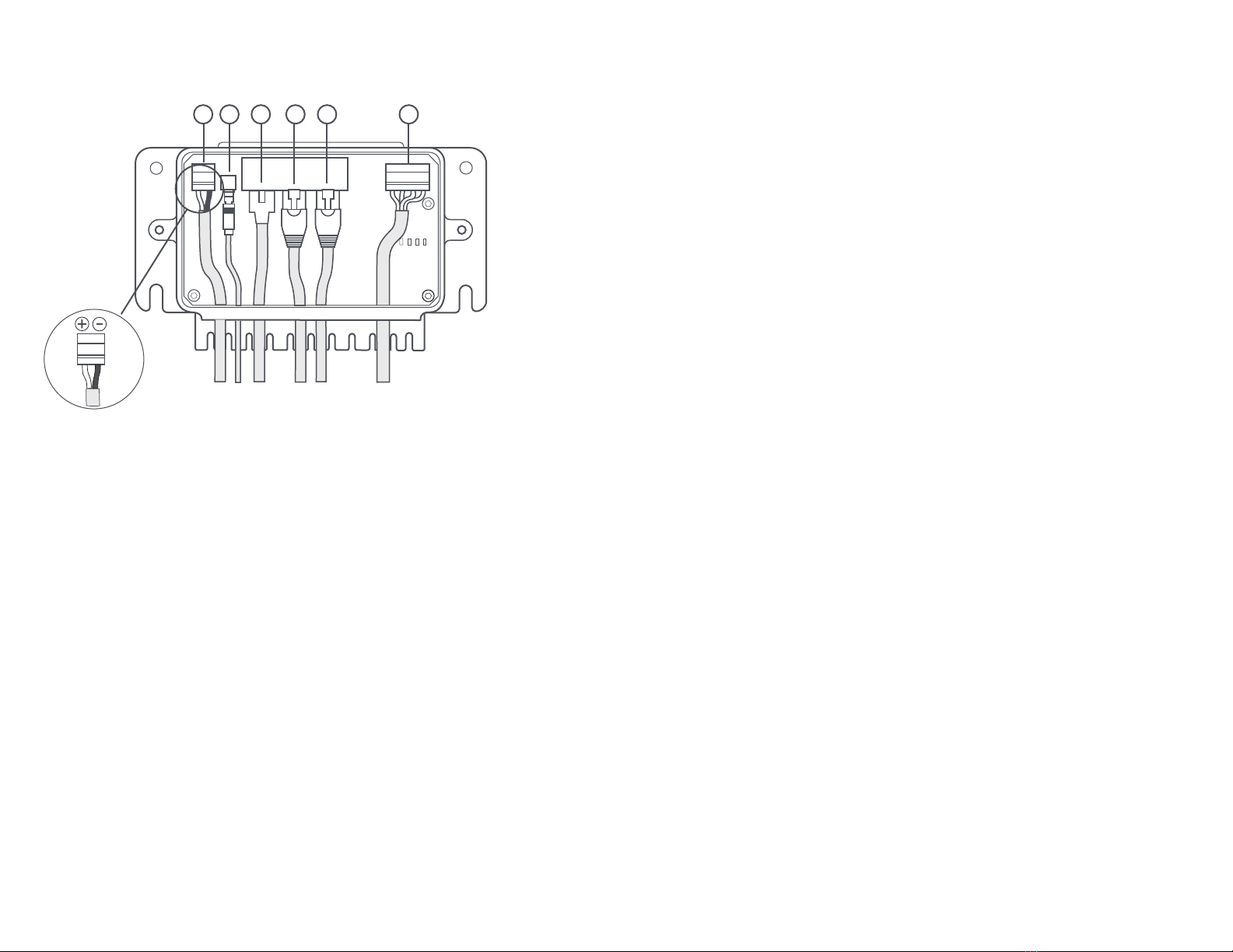
1. Power cable - Connect the power cable provided to the [Power] port in the Junction
Box and to a DC power source on your vessel. It is recommended that you use
either a 12V or 24V DC power. The power cable consists of Black for (-) negative,
White for (+) wire. Please ensure that the correct polarity is inserted into the right
terminal (Fig. 6).
2. AV Analog cable - Connect the AV Analog cable to the Junction Box [AV] port and
the other end to your analog monitor (if required).
3. Camera harness - Connect the end of the camera harness to the ethernet port in
the Junction Box marked [Camera].
4. Controller cable - Connect the ethernet cable to the Junction Box [Controller/MFD]
port (4) and the other end the Joystick Controller.
5. MFD cable - Connect the ethernet cable to the Junction Box [Controller/MFD] port
(5) on and the other end to your MFD.
6. NMEA 0183 socket - For devices that require input from NMEA 0183 devices,
connect the NMEA 0183 data source to the [NMEA] socket in the Junction Box
using 24-20 AWG cables and the output from the NMEA device to the Rx pins in
the Junction Box.
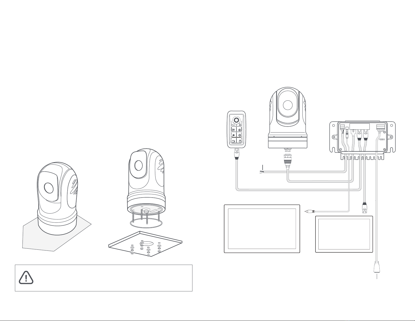
Connecting the Cables
Junction Box
The Junction Box is the primary means to provide power to the Camera and Joystick
Controller. It also serves as a hub for data transmission and interfacing point to other
connected network devices.
Fig. 6
Fig. 5
1. Power
2. AV
3. Camera
4. Controller/MFD
5. Controller/MFD
6. NMEA
123465
You can choose to display the video output of your Ulysses Micro to a supported
MFD via IP (ethernet), an analog monitor via AV analog cable and/or a laptop
computer (via web browser). Instructions are as follows:
1. Connecting to a MFD:
Connect the ethernet cable from the [Controller/MFD] port in the Junction Box to a
compatible MFD. The camera will work with Garmin MFD with OneHelm. If you are
using a Garmin’s MFD, you should see a Ulysses Micro icon displayed on the
‘OneHelm’ page after powering up both the MFD and camera system. Launch the
Ulysses Micro icon to use the camera.
If you are using a Furuno or Navico’s MFD, you will need to configure the camera
system to communicate in the correct network environment by using a web browser
or an analog monitor/Joystick Controller. Refer to setup section on the next page.
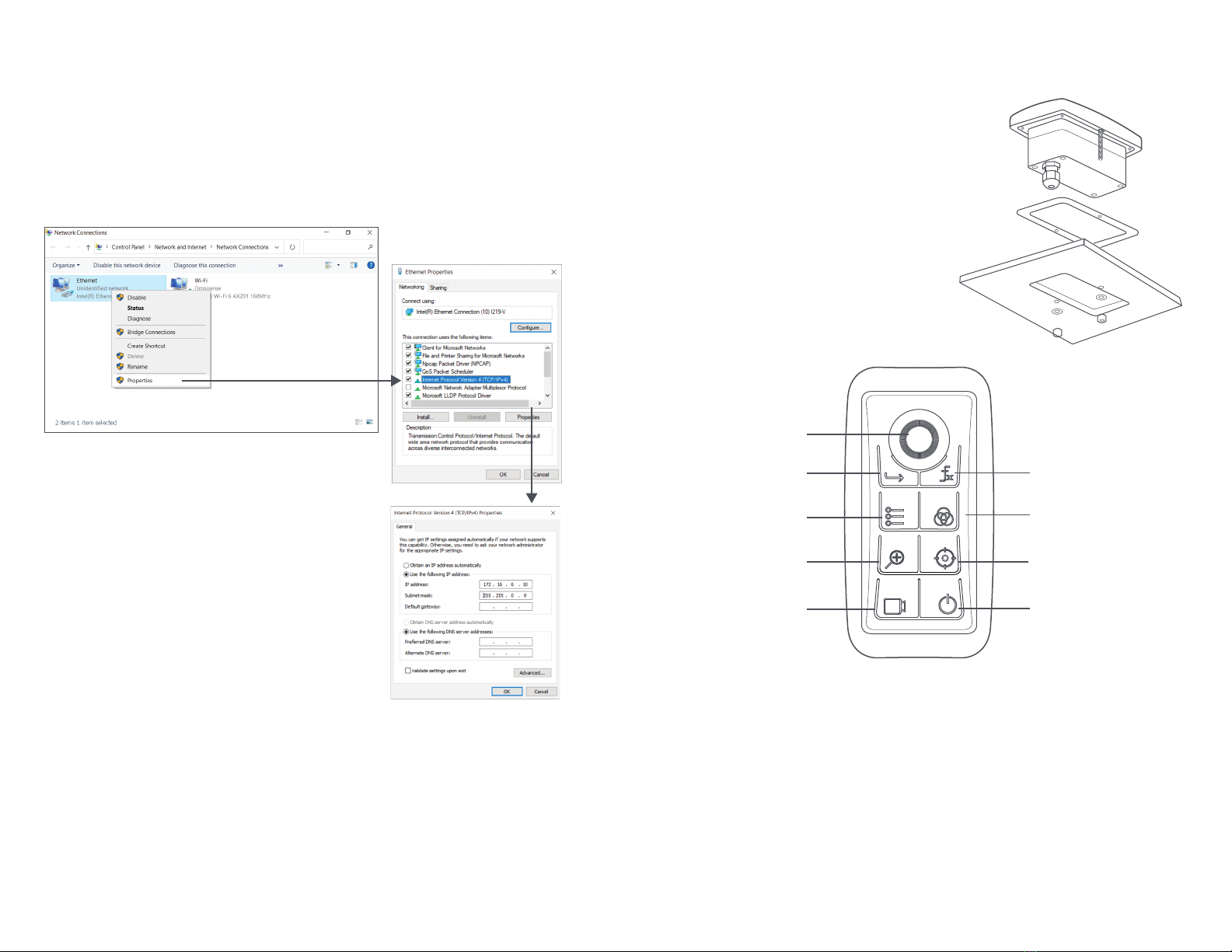
2. Connecting to a PC:
Connect an Ethernet cable from your PC to Ethernet port on the Junction Box
marked [Controller/MFD]. On your web browser, enter the default IP address as
indicated at the base of the turret and login with the following:
Username: admin
Password: 12345
Full control of the camera can now be accessed through the Web browser.
3. Connecting to an analog monitor:
Connect the AV analog cable from the [AV] port in the Junction Box to your analog
monitor. The display will appear on the screen. Use the Joystick Controller to control
the camera.
Connecting to your Display via Ethernet (Options)