manuals.online logo
Brands
  1. Home
  2. •
  3. Brands
  4. •
  5. EverFocus
  6. •
  7. Digital Camera
  8. •
  9. EverFocus HDCCTV EZH5242 User manual

EverFocus HDCCTV EZH5242 User manual

Model No. EZH5242
1080p HDcctv IP66
IR Bullet Camera
User Manual
Please read this manual irst to ensure correct installation and operation. This manual should be
retained or uture re erence. The in ormation in this manual was current when published. The
manu acturer reserves the right to revise and improve its products. All speci ications are
there ore subject to change without notice.
PRECAUTIONS
1. Do not install t e camera near electric or magnetic fields.
Install the camera away rom TV/radio transmitters, magnets, electric motors, trans ormers
and audio speakers, because the electromagnetic ields generated by these devices may
distort the video image or otherwise inter ere with camera unctions.
2. Never disassemble t e camera beyond t e recommendations in t is manual, nor apply
materials to it ot er t an t ose recommended erein.
Improper disassembly or introduction o corrosive materials may result in equipment ailure
or other damage.
3. Try to avoid pointing t e camera toward t e sun.
In some circumstances, direct sunlight may cause permanent damage to the sensor and/or
internal circuits. It may also create unbalanced illumination that may be beyond the camera’s
ability to compensate.
4. Keep t e power cable away from water and ot er liquids. Never touc t e power cable
wit wet ands.
Touching a wet power cable with your hands or touching the power cable with wet hands
may result in electric shock.
5. Never install t e camera in areas exposed to oil, gas or solvents.
Oil, gas or solvents may cause equipment ailure, electric shock or, in extreme cases, ire.
6. Cleaning
For cameras with interchangeable lenses, do not touch the sur ace o the sensor directly
with your hands. Use lens tissue or a cotton tipped applicator and ethanol to clean the
sensor and the camera lens. Use a damp so t cloth to remove any dirt rom the camera body.
Do not use complex solvents, or corrosive or abrasive agents to clean any part o the camera.
7. Do not operate t e camera beyond t e specified temperature, umidity and power source
levels. T is camera is suitable for indoor and outdoor operation only.
Use the camera at temperatures between -40°C~50°C (-40°F~122°F) in an IP66 complaint
environment. This device is not rated as submersible. The input power source should be
12VDC or 24VAC. T e use of a properly fused or “Class 2 Limited Power Source” power
supply is ig ly recommended.
8. Mounting
Select a solid mounting sur ace that will support the weight o the camera and any
additional loading rom wind, snow, ice or other actors. Securely attach the camera to the
mounting sur ace using screws and anchors that will properly support the camera. I
necessary, (e.g. when mounting the camera to a drop ceiling, or unsupported ceiling) use a
sa ety wire to provide additional support or the camera.
Federal Communication Commission Interference Statement
This equipment has been tested and found to comply with the limits for a Class B digital device,
pursuant to Part 15 of the FCC Rules. These limits are designed to provide reasonable
protection against harmful interference in a residential installation. This equipment generates,
uses and can radiate radio frequency energy and, if not installed and used in accordance with the
instructions, may cause harmful interference to radio communications. However, there is no
guarantee that interference will not occur in a particular installation. If this equipment does
cause harmful interference to radio or television reception, which can be determined by turning
the equipment off and on, the user is encouraged to try to correct the interference by one of the
following measures:
- Reorient or relocate the receiving antenna.
- Increase the separation between the equipment and receiver.
- Connect the equipment into an outlet on a circuit different from that to which the receiver
is connected.
- Consult the dealer or an experienced radio/TV technician for help.
FCC Caution: Any changes or modifications not expressly approved by the party responsible for
compliance could void the user's authority to operate this equipment.
This device complies with Part 15 of the FCC Rules. Operation is subject to the following two
conditions: (1) This device may not cause harmful interference, and (2) this device must accept
any interference received, including interference that may cause undesired operation.
This Product is RoHS compliant.
ATTENTION! This is a class A product which may cause radio interference in a domestic
environment; in this case, the user may be urged to
take adequate measures.
WEEE
Your EverFocus product is designed and manufactured with high quality
materials and components which can be recycled and reused.
This symbol means that electrical and electronic equipment, at their end-of-life,
should be disposed of separately from your household waste.
Please, dispose of this equipment at your local community waste
TABLE OF CONTENTS
1. INTRODUCTION .......................................................................................................................... 1
1.1 FEATURES ......................................................................................................................................... 1
1.2 PACKAGE
CONTENTS ........................................................................................................................ 2
1.3 SPECIFICATIONS ............................................................................................................................... 3
2. CAMERA OVERVIEW ................................................................................................................... 5
2.1
DIMENSIONS ................................................................................................................................... 5
2.2
NAMES
AND
FUNCTIONS
OF
PARTS................................................................................................. 5
3. INSTALLATION ............................................................................................................................ 6
3.1
WIRING
AND
MOUNTING ............................................................................................................... 6
3.2 ADJUSTING
THE
CAMERA ................................................................................................................ 8
4. CAMERA SETUP ........................................................................................................................ 10
4.1
CONTROL
STICK
MOVEMENTS ...................................................................................................... 10
4.2
OSD
OPERATION ............................................................................................................................ 11
5. CONFIGURATION WITH THE OSD ............................................................................................... 12
5.1
LENS .............................................................................................................................................. 12
5.2
EXPOSURE ..................................................................................................................................... 12
5.3
WHITE
BALANCE............................................................................................................................ 14
5.4
DAY
&
NIGHT ................................................................................................................................. 15
5.5
NR
–
NOISE
REDUCTION ................................................................................................................ 16
5.6
SPECIAL ......................................................................................................................................... 17
5.7
ADJUST .......................................................................................................................................... 19
5.8
RESET ............................................................................................................................................. 19
5.9
EXIT ............................................................................................................................................... 19
1
1. INTRODUCTION
The EZH5242 is an HDcctv outdoor IR bullet camera with true Day/Night capability in an IP66
vandal resistant housing. Based on a 1/3” Panasonic 2.1 megapixel progressive scan sensor and
2.8~10mm vari ocal megapixel lens or HD 1080p resolution 100% digital images, it delivers
vastly superior video quality compared to traditional CCTV images. This superior resolution not
only captures more critical evidentiary in ormation, but the inherent ability or megapixel
video also extends the area o coverage, expedites completion o investigations, resolves
complaints and reduces both capital and operational costs. Designed with 44 long li espan IR
LEDs, the EZH5242 can capture images at up to 84m /275 eet in low or no light environments.
This highly advanced imaging system also incorporates state o the art optical enhancement
technologies: EverFocus Tone Reproduction (ETR) electronically balances lighting in
challenging or unbalanced lighting conditions; Lens Shading Compensation compensates to
eliminate arti icial shadows caused by attenuation o light as it traverses the outer portions o
the lens; EverFocus Enhanced Contrast Technology (EFECT) dramatically improves imaging in
reduced visibility conditions, cutting through smoke and og that would blind other camera
systems; Polestar SENS-UP light low enhancement or ull motion color in low light conditions
without ghosting combines with EFALCONR - EverFocus Adaptive Luminance Compensated
Optimized Noise Reduction to maximize image luminance and clarity while conserving DVR
disk storage space; digital zoom with electronic PTZ to ine tune ield o view; image lip and
rotate, and much, much more.
No major upgrade to the IT network is required to deploy this power ul technology; HDcctv
cameras communicate at digital speeds up to 1.5Gb/s over existing or new coaxial cable (RG59
or other types or longer distances), using industry standard BNC connectors. With its 3-axis
positioning, vari ocal 2.8~10mm megapixel auto iris lens, IP66 operation down to -40 degrees
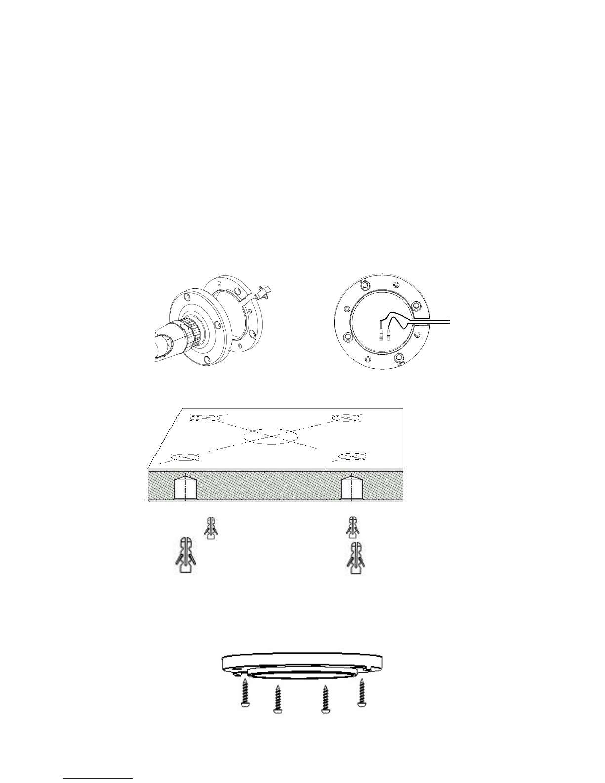
and easy mounting to a 4” electrical box, 1” conduit or directly to any lat sur ace the EZH5242
delivers lexible, robust coverage in a wide range o demanding surveillance environments
while delivering stunning HD image quality.
1.1 FEATURES
•2.1 Megapixel 1920x1080p HDcctv HD video over coax or superlative image detail
•2.8~10mm AI VF megapixel lens plus optional electronic lens shading compensation captures
the desired ield o view with uni orm image illumination
•True Day / Night operation with 44 IR LEDs or e ective range up to 84 m / ~ 275 t
•Provides ICR / 2D & 3D DNR / EFALCONR/SENS-UP (up to 60x) to improve picture clarity in low
light scenes
•ETR (EverFocus Tone Reproduction) to deliver properly exposed images despite bright light
sources, deep shadows and/or unbalanced lighting in the same scene
2
•HSBLC/BLC with programmable zones aid in control o image exposure and contrast in the
presence o concentrated light sources such as automobile headlights or rom deep shadows
surrounding objects o interest
•EFECT (EverFocus Enhanced Contrast Technology) delivers recognizable images despite
inter erence rom og or smoke
•Digital zoom increases e ective lens magni ication and includes PIP viewer or adjusting
electronic pan, tilt and zoom
•Up to 8 Privacy Zones programmable or size, location and color detection
•Dead pixel compensation or increased clarity and extended service li e
•Easy to use OSD setup menu or digital signal processing eature control
•SD TV Out to aim and ocus using a standard hand held test monitor
•Dual Voltage Power Source 12V DC / 24V AC
•
Weather Resistant IP66 rated with per ormance in cold climates down to -40 degrees
1.2 PACKAGE CONTENTS
•1 x Camera Unit
•1 x Speedy Mount Ring
•1 x User Manual
•1 x Video Test Cable
•1 x Power Supply Pigtail
•1 x Mounting Kit
Mounting kit includes:
•4 x Long Screws ( or attaching Speedy Mount Ring to mounting sur ace)
•4 x Short Screws ( or connecting camera base to Speedy Mount Ring)
•4 x Expanding Anchors
•1 x 4 mm Hex key ( or adjusting camera position)
•1 x 1.5 mm Hex key ( or adjusting Sunshield and set screw in base)
•1x T10 Torx key ( or adjusting Lock tab and lock tab screw)
•1 x Mounting Template
3
1.3 SPECIFICATIONS
Pickup Device 1/3” Panasonic 2.1 megapixel Color Progressive CMOS sensor
Image Pixels 1920 (H) x 1080 (V) with 2.75µ x 2.75µ pixel size
HDcctv Image Area Dimensions
5.28 mm (H) x 2.97 mm (W); ø 6.06 mm area diagonal
Sensitivity 0.4 lux / F=1.2; 0 lux (IR LED ON)
S/N Ratio Max. 50dB
Video Format Main Output HDcctv
Video Resolution/Mode Main
Output 1920 x 1080p 30 / 25
Main Output Connector BNC
Video Format Test Output NTSC / PAL selectable
Test Output Connector Pin header; adapter cable to BNC supplied
Lens Type DC Iris Megapixel Vari ocal lens, =2.8mm~10mm
IR LEDs 44 LEDs with wavelength o 850nm
IR Range Up to 84m / 275 eet (depends on scene IR re lectivity)
True Day/Nig t Control Yes (Auto IR cut ilter removal)
OSD Menu Yes (controlled rom 5-axis joystick control)
Electronic S utter Auto / Manual selectable
Angle of View
Wide
Diagonal: 94.5°
Horizontal: 86.6°
Vertical: 55.9°
Narrow
Diagonal: 33.7°
Horizontal: 29.6°
Vertical: 16.9°
ETR (EverFocus Tone
Reproduction) O / Low / Medium / High [Electronic Wide Dynamic Range]
Lens S ading Compensation O / On
Back Lig t Compensation
(HSBLC=Hig lig t Suppression
Back Lig t Compensation)
O / BLC / HSBLC
BLC (select areas rom 8 x 15 grid)
HSBLC (4 zones programmable or size and location)
Auto Gain Control Low / Middle / High
Auto W ite Balance ATW / Push / Manual / Outdoor / Indoor
DNR
Common Level Adjust 0~100
2D DNR – O / On; 3D DNR – O / On
EFALCONR [EverFocus Adaptive Luminance Compensated
Optimized Noise Reduction] – O / On
4
EFECT (EverFocus En anced
Contrast Tec nology)
Low / Middle / High
EFECT improves contrast in smoke, og and similar conditions]
Digital Zoom 2X~64X with optional PIP mode
or ease o electronic pan / tilt alignment
Motion Identification On screen highlighting o changing areas
OSD Text Color Control Custom camera title; ability to change text display color and
turn black text outline o / on to contrast with scene
Image Flip O /H Flip/V Flip/HV Flip (rotate 180°)
Programmable Privacy Zones 8 areas independently adjustable or size, location, color
OSD Text Language Selection English, Traditional Chinese , Simple Chinese, Japanese
Dead Pixel Compensation Dynamic Method O / On / Auto;
Static Method O / On; separate adjustable threshold levels
Polestar SENS-UP Low light boost 2X~60X (recommended no more than 8X
without care ul consideration o application conditions)
Power Source & Consumption DC12V 650mA 7.8W (Max)
AC24V 430mA 10W (Max)
Dimensions
(In line) 359.9mm/14.17“ (L) x Φ105.5mm/Φ4.15“ Diameter
(W)
(Right angle) 312.7mm/12.3“(L) x 145mm/5.7“(H) x
Φ105.5mm/Φ4.15“ Diameter (W)
Weig t 1.5 kg / 3.31 lbs
Mounting
Speedy-mount ring attaches easily to mounting sur ace and
its 4” electrical box pattern; camera base attaches to ring or
can be removed to it 1” conduit thread.
Operating Environment -40°C~50°C / -40°F~122°F
Weat er Resistant IP66 rated
Certifications FCC / CE
5
Sunshield & sunshield screw
Lock tab & lock tab screw
Front cover
2. CAMERA OVERVIEW
2.1 DIMENSIONS
2.2 NAMES AND FUNCTIONS OF PARTS
Unscrew the ront cover o
the camera housing to reach
the control stick and the lens
adjustments.
Lens Adjustments
Focus lever (FAR-NEAR)
Zoom lever (WIDE –TELE)
Control Stick
Be ore unscrew the ront cover,
please, remove
the sunshield and
the lock tab.
Power Reset button
Speedy-mount ring
6
3. INSTALLATION
Steps:
1. Wire and mount the camera. See 3.1
2. Adjust the camera position. See 3.2
Warning
To prevent electrical shock, turn o the electrical power be ore making electrical connections.
3.1 WIRING AND MOUNTING
1. Use the template and an appropriate tool to drill 4 holes to attach the Speedy-mount ring.
(Note: I the wires rom the camera will be routed on the sur ace, use a pliers or other suitable tool
to grasp the iller closing the sur ace wire slot and twist to remove the iller to open the wire slot.
I the wires will be routed through the rear o the camera leave the sur ace wire slot iller in place.)
2. Push the plastic anchors into the 4 holes.
3. Place the Speedy-mount ring against the anchoring sur ace so that the holes line up. Insert the our
long screws and tighten them irmly.
7
Video & Power cables
Power Socket
BNC
4. I you don’t plan to run the cables along the sur ace o the wall or anchoring sur ace, drill a 1” hole
or the camera’s two cables in the middle o the circular area “inside” o the Speedy-mount ring.
Pull the cables to be connected to power & video cables rom the ceiling or wall.
5. Feed the two main cables through the 1” hole. Attach the camera to the Speedy-mount ring with
the 4 short screws provided.
6. Connect the power, test cable, video cables rom the Camera to power, handheld monitor and
HDcctv DVR.
8
3.2 ADJUSTING THE CAMERA
Adjust the viewing angle to the desired direction. With this 3-axis positioning system, installers can
capture images rom virtually any angle. The camera can be adjusted around these 3 axes:
1st axis
2nd axis
3rd axis
Use a hexagon key to loosen this screw to rotate the camera 360° around its long axis.
Use a hexagon key to loosen this screw to rotate the camera 90°
around this joint.
Twist the base care ully counterclockwise until it unscrews rom
the lock ring to be able to rotate the camera 360° around this axis.
Once the camera is in position, turn the lock ring clockwise until it
locks against the base to ix the camera in position.
Tighten the set screw on the ring to ully secure the position.
9
Install t e Suns ield
To install or remove the sunshield, use the hexagon wrench provided to loosen the screw securing the
sunshield.
Note: When properly installed, the rear o the sunshield should be even with the rear o the
camera body. I you extend the sunshield to ‘shade’ the lens, the shield could compromise image
quality.
Slide the rib on the inside o the sunshield into the rail on the
outside o the camera body – rom ront to back.
Tighten this sunshield screw
10
4. CAMERA SETUP
This camera utilizes
an On Screen Display
(OSD) user setup
menu that can be
navigated by a control
stick marked by (3 )
in the photo on the
right) that is located
next to the lens at the
ront o the camera
housing. To access
this control stick, (1)
loosen the screws and
remove the Sunshield
and the Lock tab. (2) Twist the ront cover care ully counterclockwise until the ront cover unscrews
rom the camera housing.
4.1 CONTROL STICK MOVEMENTS
To con igure options on the OSD setup menu, move the control stick to do the actions described
below.
① ENTER / CONFIRM
Press this button (by pressing straight down on the stick) to display the OSD’s main menu on the
monitor that you have connected directly or indirectly to the camera’s video connector. Also
press this button to con irm changes and to open the submenus when they’re available and
selected. (Menu items with a “
<┘
” symbol at the end contain submenus. For adjusting submenu
items, select the desired menu item with the  and  buttons and press the ENTER button to
open the desired submenu. Use the  and  buttons to toggle between value options.)
② SCROLL RIGHT
Press this button (by pressing the control stick to the right) to move the on-screen cursor to the
right to select items or to adjust the level/intensity o a selected unction. The level/intensity
increases when this button is pressed.
③ SCROLL LEFT
Press this button (by pressing the control stick to the le t) to move the cursor to the le t to select
items or to adjust the level/intensity o a selected unction. The level/intensity decreases when
this button is pressed.
Remove the Lock tab
and the Sunshield
Twist the ront cover
care ully
The control stick
11
④ SCROLL DOWN
Press this button (by pressing the control stick in the “down” direction) to scroll the on-screen
cursor downwards between menu items.
⑤ SCROLL UP
Press this button (by pressing the control stick in the “up” direction) to scroll the on-screen
cursor upwards between menu items.
4.2 OSD OPERATION
1. Open t e OSD menu
Press the ENTER button to open the OSD’s main
(“setup”) menu on your screen.
2. Scroll wit t e cursor buttons to select menu
items
Use the  and  buttons to move the cursor up
and down to scroll to the desired menu items.
3. Toggle between t e rig t- and options (modes)
of eac menu item
Use the  and  buttons to change the modes o menu items and to access the submenus
o those modes (to adjust the parameters or values o submenu items – where applicable).
Menu items with a “<┘” symbol at the end contain submenus. (I the right-hand menu title
is “SET”, it means that there are no modes to choose rom, only a settings submenu or the
le t-hand main menu item.)
4. Open submenus
Right-hand items (or “modes”) with a “<┘” symbol at the end contain submenus. For
adjusting submenu items, select the desired menu item with the  and  buttons, then
select the desired submenu title (or “mode”) to the right o the menu item with the  and
 buttons, then press ENTER to open the submenu.
5. Return to t e previous page or exit t e OSD quickly
Scroll to RETURN and scroll between the RET and END options. I RET is selected, press
ENTER to return to the previous page. I END is selected, press ENTER to exit the OSD.
6. Exit t e OSD menu
Scroll to EXIT and press the ENTER button to exit the OSD menu.
12
5. CONFIGURATION WITH THE OSD
Once you have opened the OSD’s main menu on
your screen, use the UP and DOWN buttons to
scroll to the menu item o your choice. Use the
LEFT and RIGHT buttons to toggle between the
di erent modes (right-hand column) o the
menu item.
5.1 LENS
It is the DC mode as a actory de ault.
5.2 EXPOSURE
Once you have opened the OSD’s main menu on your screen, use the UP and DOWN buttons to
scroll to the “EXPOSURE” menu item. Press the ENTER button to open the Exposure submenu.
SHUTTER
Use the LEFT and RIGHT buttons to adjust the shutter speed. Choose rom 1/30 ~ 1/50000, x2 ~
x60, FLK, and AUTO. Any selection other than AUTO and 1/30 will disable the SENS-UP ield two
lines below this ield.
AGC
This stands or Auto Gain Control (basic low-light signal ampli ication). Choose rom LOW ~
HIGH. The higher the AGC, the brighter the screen, but the level o noise will also increase.
SENS-UP
SENSE UP is used to maintain a vivid screen image by automatically boosting low light levels.
Use the LEFT and RIGHT buttons to switch this unction on/o and adjust its settings.
Choose rom OFF or AUTO. AUTO has a submenu option where you can set the SENS-UP level
(x2 ~ x60). (No more than 8X SENS-UP is recommended without care ul consideration o
application conditions.)
SubmenuMain menu
13
BRIGHTNESS
Scroll to this ield and then scroll le t or right to increase or decrease the screen brightness level
(0 to 100).
ETR ( EverFocus Tone Reproduction)
ETR is an advanced orm o electronic wide dynamic range expansion used to deliver properly
exposed images despite bright light sources, deep shadows and/or unbalanced lighting in the
same scene . Choose rom OFF, LOW ~ HIGH.
EFECT (EverFocus Enh nced Contr st Technology)
EFECT analyzes the distribution o luminance across the image and processes the signal to
improve contrast and increase image clarity, by reducing e ects due to dispersion o light
caused by og, smoke and similar conditions. Choose rom OFF, LOW ~ HIGH.
BACKLIGHT
•OFF
•BLC (Backlight Compensation):
GAIN – Select LOW ~ HIGH. Video gain is adjusted automatically to correct the
exposure o subjects that are in ront o a bright light source. In the AREA setting below, you
can select the area on the image that this BLC Gain level will apply to.
AREA – Press Enter to enter the AREA setup screen’s Position mode. Use the direction
buttons to position the area selector block’s le t and top borders. Press Enter again to
activate the Size mode and use the direction buttons to select the area selector block’s right
and bottom borders. Press Enter again to see a lashing RET and non- lashing AGAIN sign.
Press Enter to return to the previous screen, or scroll right to see a non- lashing RET and a
lashing AGAIN sign. Press Enter i you want to change the position o the area selector
block, or scroll back to RET and press Enter to return to the previous screen (BLC). The BLC
Gain setting above will apply to this area only.
DEFAULT – Press Enter in this ield to return the area selector block to its de ault
position and size.
•HSBLC (Highlight Suppression BLC):
SELECT – Scroll sideways to select the HSBLC area selector block you want to edit. The
block associated with the selected area number will start lashing when you select it. All
changes in the DISPLAY ield below will apply to this block only. The HSBLC Level setting
(below) will only apply to the blocks that have been activated.
DISPLAY – Select OFF to hide the selected area indicator block. Select ON to display the
block and activate its block-positioning submenu. In ON mode, press Enter to enter the
submenu and use the direction buttons to select the top and right position o the area
block. Press Enter again to activate the Size mode and use the direction buttons to select
the bottom and le t borders o the area selector block. Press Enter again to see a lashing
RET and non- lashing AGAIN sign. Press Enter to return to the previous screen, or scroll
14
right to see a non- lashing RET and a lashing AGAIN sign. Press Enter i you want to change
the position o the area selector block, or scroll back to RET and press Enter to return to the
previous screen (HSBLC).
LEVEL – Scroll sideways to increase or decrease the HSBLC level in all the area blocks.
The lower the value, the more intense the HSBLC.
MODE – Choose between ALL DAY mode and NIGHT (only) mode. NIGHT mode will
activate HSBLC only when light levels all to levels associated with nighttime.
BLACK MASK – Turn the black masking e ect o HSBLC on or o .
DEFAULT – Press Enter in this ield to return all area selector blocks to their de ault
positions and sizes. All other HSBLC settings will also return to their de aults.
5.3 WHITE BALANCE
The screen color can be adjusted by using the HITE
BALANCE unction.
1. Scroll to HITE BALANCE on the main menu and
use the LEFT and RIGHT buttons to toggle between
this menu item’s ive mode options. The modes or
WHITE BALANCE are ATW, AWB, INDOOR,
OUTDOOR, and MANUAL.
2. Select the desired mode and press ENTER to open
the mode’s adjustment submenu, where relevant.
ATW (Auto Trace W ite Balance)
This mode can be used to view areas with a color temperature range o 1800°K to 10500°K (e.g.,
around luorescent lights, outdoors, around sodium vapor lamps or inside tunnels).
AWC -> SET
Select this to allow the camera to automatically adjust the white balance under all conditions.
Press the Enter button to “set” (adjust) the white balance automatically.
INDOOR
Select this mode when the color temperature o the video image is similar to that ound in
indoor environments (around 5100 to 5300°K).
OUTDOOR
Select this mode when the color temperature o the video image is similar to that ound in
outdoor environments (around 3,000°K to 3,200°K).
MANUAL
This mode enables more precise adjustments. Increase and/or decrease the Red Gain and Blue
Gain values to suit the light in the surveillance area. Press Enter to access this mode’s submenu
and change the Red and Blue levels.
15
5.4 DAY & NIGHT
Use this menu item to select COLOR, B/W, EXTERNAL, or
AUTO mode.
Use the LEFT and RIGHT buttons to select the mode.
Press ENTER to access the selected mode’s setting
submenu, where applicable.
AUTO mode switches to a B&W eed in low light
conditions and then switches back to a Color eed
in the daytime. The switch-over moments or this
mode are triggered when the speci ied AGC level is
reached. Press Enter to open the submenu and set
the DELAY (the number o seconds that the camera
will wait be ore switching between DAY and NIGHT
modes i the threshold light level is reached – to
negate temporary light changes) and the D->N (the light level at which the camera will switch
rom DAY mode to NIGHT mode), and the N->D (the light level at which it will switch rom
NIGHT to DAY mode).
Note: The AGC Level must be set as middle or high in order to employ the auto switching
unction.
B/W mode is ideal or NIGHTTIME. In this mode,
the camera is orced to deliver a B&W eed
during daytime and nighttime. Press Enter to
access this mode’s submenu and set the BURST,
IR SMART and IR LED options ON/OFF.
The IR SMART option has a submenu where you
can select the IR LEVEL (intensity) and AREA. IR
Smart technology adjusts the IR lighting to ocus
on a selected area in the image and to provide
just enough light to illuminate that area. The
AREA submenu lets you select which area and
size that would be. Select a dark part o the
image, will let the whole image become brighter.
16
COLOR mode is ideal or DAYTIME. In this mode, the camera is orced to deliver a Color eed
during daytime and nighttime.
EXTERNAL mode switches to a B&W eed in low light conditions and then switches back to a
Color eed in the daytime. It is based on the camera’s external light sensor at the ront o the
camera body.
5.5 NR – NOISE REDUCTION
•LEAVEL as 10 per ormances when digital
“video noise” levels are reduced. When
recording digitally, the image ile size can
also be lessened with noise reduction. The
higher the 2DNR and 3DNR settings (options
are rom Low to High), the more noise is
iltered out.
•Press Enter to access the NR submenu (2DNR
and 3DNR) and select which one o the
unctions you want to switch ON and which
ones OFF.
•Select the Level o each unction.
•I you switch 3DNR ON, press Enter to access
its submenu and set its S-Level and E-Level (see the image on the right).
S-Level: Set up the AGC level to automatically start the 3D NR unction.
E-Level: Set up the AGC level to automatically stop the 3D NR unction.
•EFALCONR [EverFocus Adaptive Luminance
Compensated Optimized Noise
Reduction] –optimized to reduce noise in low
light scenes while maximizing image
luminance and clarity. Choose “OFF” or “ON”.

Other manuals for HDCCTV EZH5242

1

Other EverFocus Digital Camera manuals

EverFocus EBD-330A User manual

EverFocus

EverFocus EBD-330A User manual

EverFocus Eq250 User manual

EverFocus

EverFocus Eq250 User manual

EverFocus EMC920F Series User manual

EverFocus

EverFocus EMC920F Series User manual

EverFocus ED635 Technical manual

EverFocus

EverFocus ED635 Technical manual

EverFocus EM900F EZ.HD SERIES User manual

EverFocus

EverFocus EM900F EZ.HD SERIES User manual

Popular Digital Camera manuals by other brands

Sony ILCE-QX1 Service manual

Sony

Sony ILCE-QX1 Service manual

Canon PowerShot G5 parts catalog

Canon

Canon PowerShot G5 parts catalog

ARRI 535B Quick glance

ARRI

ARRI 535B Quick glance

Casio EX-M1 - EXILIM Digital Camera release note

Casio

Casio EX-M1 - EXILIM Digital Camera release note

dji Osmo Pocket Disclaimer and safety guidelines

dji

dji Osmo Pocket Disclaimer and safety guidelines

König Electronic SEC-CAM710 manual

König Electronic

König Electronic SEC-CAM710 manual

Nikon CoolPix P6000 quick start guide

Nikon

Nikon CoolPix P6000 quick start guide

gobandit LIVE GBZ0500 user manual

gobandit

gobandit LIVE GBZ0500 user manual

Avonic CM41-VCUC quick guide

Avonic

Avonic CM41-VCUC quick guide

Avue AV762WDIR Guick Start Guide

Avue

Avue AV762WDIR Guick Start Guide

Sony CD Mavica MVC-CD250 operating instructions

Sony

Sony CD Mavica MVC-CD250 operating instructions

Rosco VISION SAFE-T-SCOPE STSK7145 Installation & user manual

Rosco

Rosco VISION SAFE-T-SCOPE STSK7145 Installation & user manual

Panasonic LUMIX DMC-FZ18 operating instructions

Panasonic

Panasonic LUMIX DMC-FZ18 operating instructions

Cobra Digital DCA1215 Specifications

Cobra Digital

Cobra Digital DCA1215 Specifications

Casio EX-Z650 - EXILIM Digital Camera user guide

Casio

Casio EX-Z650 - EXILIM Digital Camera user guide

PIKO PK1903-P user guide

PIKO

PIKO PK1903-P user guide

PhaseOne XF quick guide

PhaseOne

PhaseOne XF quick guide

Vivitar Vivicam 3740 user manual

Vivitar

Vivitar Vivicam 3740 user manual

manuals.online logo
manuals.online logoBrands
  • About & Mission
  • Contact us
  • Privacy Policy
  • Terms and Conditions

Copyright 2025 Manuals.Online. All Rights Reserved.