manuals.online logo
Brands
  1. Home
  2. •
  3. Brands
  4. •
  5. Onkyo
  6. •
  7. DVD Player
  8. •
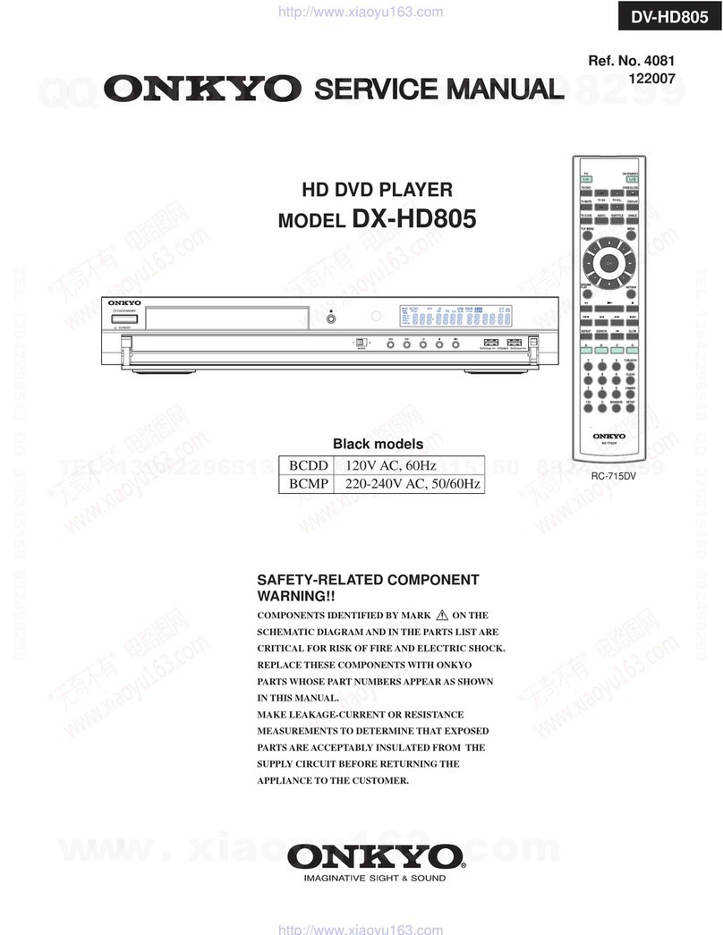
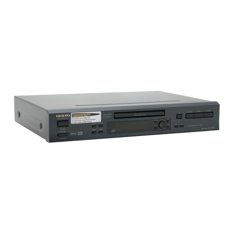
  9. Onkyo RDV-1 User manual

Onkyo RDV-1 User manual

Getting Started 8
Basic Playback 22
Advanced Playback 29
Others 61
Before sing Your DVD Player 2
Quick Control and
Performance Options 38
Function Setup 46
Remote Controller 56
Thank you for purchasing the Integra
RESEARCH DVD AUDIO/VIDEO Player.
Please rea this manual thoroughly before
making connections an plugging in the unit.
Following the instructions in this manual will
enable you to obtain optimum performance
an listening enjoyment from your new player.
Please retain this manual for future reference.
RDV-1
DVD A DIO/VIDEO Player
Instruction Manual
RDV-1 US/Asia 29342995
RDV-1(US_E)Cover.p65 10/4/00, 17:031
2
Important Safeguards
CAUTION:
TO REDUCE THE RISK OF ELECTRIC SHOCK, DO NOT
REMOVE COVER (OR BACK). NO USER-SERVICEABLE
PARTS INSIDE. REFER SERVICING TO QUALIFIED
SERVICE PERSONNEL.
triangle, is intended to alert the user to the presence of uninsulated
“dangerous voltage” within the product’s enclosure that may be of
sufficient magnitude to constitute a risk of electric shock to persons.
The exclamation point within an equilateral triangle is intended to alert
the user to the presence of important operating and maintenance
(servicing) instructions in the literature accompanying the appliance.
1. Read Instructions – All the safety an operating instructions
shoul be rea before the appliance is operate .
2. Retain Instructions – The safety an operating instructions
shoul be retaine for future reference.
3. Heed Warnings – All warnings on the appliance an in the
operating instructions shoul be a here to.
4. Follow Instructions – All operating an use instructions
shoul be followe .
5. Cleaning – Unplug the appliance from the wall outlet
before cleaning. The appliance shoul be cleane only as
recommen e by the manufacturer.
6. Attachments – Do not use attachments not recommen e
by the appliance manufacturer as they may cause
hazar s.
7. Water and Moisture – Do not use the appliance near water
–for example, near a bath tub, wash bowl, kitchen sink, or
laun ry tub; in a wet basement; or near a swimming pool;
an the like.
8. Accessories – Do not place the appliance on an unstable
cart, stan , tripo , bracket, or table. The appliance may
fall, causing serious injury to a chil or a ult, an serious
amage to the appliance. Use only with a cart, stan ,
tripo , bracket, or table recommen e by the
manufacturer, or sol with the appliance. Any mounting of
the appliance shoul follow the manufacturer’s
instructions, an shoul use a mounting accessory
recommen e by the manufacturer.
9. An appliance an cart
combination shoul be
move with care. Quick stops,
excessive force, an uneven
surfaces may cause the
appliance an cart
combination to overturn.
10. Ventilation – Slots an openings in the cabinet are
provi e for ventilation an to ensure reliable operation of
the appliance an to protect it from overheating, an
these openings must not be blocke or covere . The
openings shoul never be blocke by placing the
appliance on a be , sofa, rug, or other similar surface. The
appliance shoul not be place in a built-in installation
such as a bookcase or rack unless proper ventilation is
provi e . There shoul be free space of at least 5 cm an
an opening behin the appliance.
11. Power Sources – The appliance shoul be operate only
from the type of power source in icate on the marking
label. If you are not sure of the type of power supply to
your home, consult your appliance ealer or local power
company.
12. Grounding or Polarization – The appliance may be
equippe with a polarize alternating current line plug (a
plug having one bla e wi er than the other). This plug will
fit into the power outlet only one way. This is a safety
feature. If you are unable to insert the plug fully into the
outlet, try reversing the plug. If the plug shoul still fail to fit,
contact your electrician to replace your obsolete outlet.
Do not efeat the safety purpose of the polarize plug.
13. Power-Cord Protection – Power-supply cor s shoul be
route so that they are not likely to be walke on or
pinche by items place upon or against them, paying
particular attention to cor s at plugs, convenience
receptacles, an the point where they exit from the
appliance.
14. Lightning – For a e protection for the appliance uring
a lightning storm, or when it is left unatten e an unuse
for long perio s of time, unplug it from the wall outlet an
isconnect the antenna or cable system. This will prevent
amage to the appliance ue to lightning an power-line
surges.
15. Overloading – Do not overloa wall outlets, extension
cor s, or integral convenience receptacles as this can
result in a risk of fire or electric shock.
16. Object and Liquid Entry – Never push objects of any kin
into the appliance through openings as they may touch
angerous voltage points or short-out parts that coul
result in a fire or electric shock. Never spill liqui of any kin
on the appliance.
17. Servicing – Do not attempt to service the appliance
yourself as opening or removing covers may expose you to
angerous voltage or other hazar s. Refer all servicing to
qualifie service personnel.
18. Damage Requiring Service – Unplug the appliance form
the wall outlet an refer servicing to qualifie service
personnel un er the following con itions:
A. When the power-supply cor or plug is amage ,
B. If liqui has been spille , or objects have fallen into the
appliance,
C. If the appliance has been expose to rain or water,
D. If the appliance oes not operate normally by following
the operating instructions. A just only those controls
that are covere by the operating instructions as an
improper a justment of other controls may result in
amage an will often require extensive work by a
qualifie technician to restore the appliance to its
normal operation,
E. If the appliance has been roppe or amage in any
way, an
F. When the appliance exhibits a istinct change in
performance – this in icates a nee for service.
19. Replacement Parts – When replacement parts are
require , be sure the service technician has use
replacement parts specifie by the manufacturer or have
the same characteristics as the original part. Unauthorize
substitutions may result in fire, electric shock, or other
hazar s.
20. Safety Check – Upon completion of any service or repairs
to the appliance, ask the service technician to perform
safety checks to etermine that the appliance is in proper
operation con ition.
21. Wall or Ceiling Mounting – The appliance shoul be
mounte to a wall or ceiling only as recommen e by the
manufacturer.
22. Heat – The appliance shoul be situate away from heat
sources such as ra iators, heat registers, stoves, or other
appliances (inclu ing amplifiers) that pro uce heat.
PORTABLE CART WARNING
S3125A
RDV-1 US/Asia 29342995
RDV-1(US_E)p02-07.p65 10/4/00, 17:032
3
For Canadian model
This class B igital apparatus complies with Cana ian ICES-
003.
For models having a power cord with a polarized plug:
CA TION: TO PREVENT ELECTRIC SHOCK, MATCH WIDE BLADE
OF PLUG TO WIDE SLOT, FULLY INSERT.
Modele pour les Canadien
Cet appareil numérique e la classe B est conforme à la
norme NMB-003 u Cana a.
Sur les modeles dont la fiche est polarisee:
ATTENTION: POUR EVITER LES CHOCS ELECTRIQUES, INTRODUIRE
LA LAME LA PLUS LARGE DE LA FICHE DANS LA BORNE
CORRESPONDANTE DE LA PRISE ET POUSSER JUSQU’AU FOND.
For .S. model
The laser is covere by a housing which prevents exposure
uring operation or maintenance. However, this pro uct is
classifie as a Laser Pro uct by CDRH (Center for Devices an
Ra iological Health) which is a epartment of the Foo an
Drug A ministration. Accor ing to their regulations 21 CFR
section 1002.30, all manufactures who sell Laser Pro ucts must
maintain recor s of written communications between the
manufacturer, ealers an customers concerning ra iation
safety. If you have any complaints about instructions or
explanations affecting the use of this pro uct, please feel free
to write to the a ress on the back page of this manual. When
you write us, please inclu e the mo el number an serial
number of your unit.
In compliance with Fe eral Regulations, the certification,
i entification an the perio of manufacture are in icate on
the rear panel.
FCC INFORMATION FOR SER
CA TION:
The user changes or mo ifications not expressly approve by
the party responsible for compliance coul voi the user’s
authority to operate the equipment.
NOTE:
This equipment has been teste an foun to comply with the
limits for a Class B igital evice, pursuant to Part 15 of the FCC
Rules. These limits are esigne to provi e reasonable
protection against harmful interference in a resi ential
installation. This equipment generates, uses an can ra iate
ra io frequency energy an , if not installe an use in
accor ance with the instructions, may cause harmful
interference to ra io communications. However, there is no
guarantee that interference will not occur in a particular
installation. If this equipment oes cause harmful interference
to ra io or television reception, which can be etermine by
turning the equipment off an on, the user is encourage to
try to correct the interference by one or more of the following
measures:
• Reorient or relocate the receiving antenna.
• Increase the separation between the equipment an
receiver.
• Connect the equipment into an outlet on a circuit ifferent
from that to which the receiver is connecte .
• Consult the ealer or an experience ra io/TV technician
for help.
This unit contains a semicon uctor laser system an is
classifie as a “CLASS 1 LASER PRODUCT”. So, to use this
mo el properly, rea this Instruction Manual carefully. In
case of any trouble, please contact the store where you
purchase the unit. To prevent being expose to the laser
beam, o not try to open the enclosure.
CA TION:
VISIBLE LASER RADIATION WHEN OPEN AND INTERLOCK
FAILED OR DEFEATED. DO NOT STARE INTO BEAM.
CA TION:
THIS PRODUCT UTILIZES A LASER. USE OF CONTROLS OR
ADJUSTMENTS OR PERFORMANCE OF PROCEDURES OTHER
THAN THOSE SPECIFIED HEREIN MAY RESULT IN HAZARDOUS
RADIATION EXPOSURE.
The label on the
right is applie on
the rear panel
except for USA an
Cana ian mo els.
1. This unit is a CLASS 1 LASER PRODUCT an employs a
laser insi e the cabinet.
2. To prevent the laser from being expose , o not
remove the cover. Refer servicing to qualifie
personnel.
“CLASS 1 LASER
PRODUCT”
RDV-1 US/Asia 29342995
RDV-1(US_E)p02-07.p65 10/4/00, 17:033
4
1. Regional Restriction Codes (Region Number)
Regional restriction co es are built into DVD Players an
DVD-Vi eo me ia for each sales region. If the regional
co e of the DVD Player oes not match one of the
regional co es on the DVD-Vi eo, playback is not possible.
The regional number can be foun on the rear panel of
the DVD Player. (e.g. 1 for Region 1)
2. About This Manual
This manual explains the basic proce ures for operating
the DVD Player. Some DVD-Vi eo an DVD-Au io iscs o
not support the full potential of the DVD technology. Your
DVD Player may therefore not respon to all operating
comman s. Refer to instruction notes on iscs.
A “ ” mark may appear on the TV screen uring
operation. It means that the operation is not permitte by
the DVD Player or the isc.
3. Warranty Claim
You can fin the serial number on the rear panel of the
unit. In case of warranty claim, please report this number.
4. Recording Copyright
Recor ing of copyrighte material for other than personal
use is illegal without permission of the copyright hol er.
5. Power
WARNING
BEFORE PLUGGING IN THE UNIT FOR THE FIRST TIME, READ THE
FOLLOWING SECTION CAREFULLY.
The voltage of the available power supply iffers
accor ing to country or region. Be sure that the power
supply voltage of the area where the unit will be use
meets the require voltage (e.g., AC 120 V, 60 Hz) written
on the rear panel.
6. Do not touch the unit with wet hands
Do not han le the unit or power cor when your han s are
wet or amp. If water or any other liqui enters the case,
take the unit to an authorize service center for inspection.
7. Location of the unit
• Place the unit in a well-ventilate location.
Take special care to provi e plenty of ventilation on all
si es of the unit especially when it is place in an au io
rack. If ventilation is blocke , the unit may overheat an
malfunction.
• Do not expose the unit to irect sunlight or heating units
as the unit’s internal temperature may rise an shorten
the life of the pickup.
• Avoi amp an usty places an places irectly
affecte by vibrations from the speakers. In particular,
avoi placing the unit on or above one of the speakers.
• Be sure the unit is place in a horizontal position. Never
place it on its si e or on a slante surface as it may
malfunction.
• When you place the unit near a TV, ra io, or VCR, the
playback picture may become poor an the soun may
be istorte . In this case, place the unit away from the TV,
ra io, or VCR.
8. Care
From time to time you shoul wipe the front an rear
panels an the cabinet with a soft cloth. For heavier irt,
ampen a soft cloth in a weak solution of mil etergent
an water, wring it out ry, an wipe off the irt. Following
this, ry imme iately with a clean cloth.
Do not use rough material, thinners, alcohol or other
chemical solvents or cloths since these coul amage the
finish or remove the panel lettering.
9. Notes on Handling
• When shipping the unit, use the original shipping carton
an packing materials. For maximum protection, repack
the unit as it was originally packe at the factory.
• Do not use volatile liqui s, such as insect spray, near the
unit. Do not leave rubber or plastic pro ucts in contact
with the unit for a long time. They will leave marks on the
finish.
• The top an rear panels of the unit may become warm
after a long period of use. This is not a malfunction.
• When the unit is not in use, be sure to remove the isc
an turn off the power.
• If you o not use the unit for a long perio , the unit may
not function properly in the future. Turn on an use the
unit occasionally.
10. To Obtain a Clear Picture
The unit is a high technology, precision evice. If the optical
pick-up lens an isc rive parts are irty or worn own,
the picture quality becomes poor. To obtain a clear
picture, we recommen regular inspection an
maintenance (cleaning or parts replacement) every 1,000
hours of use epen ing on the operating environment. For
etails, contact your nearest ealer.
11. Notes on Moisture Condensation
Moisture condensation damages the unit.
Please read the following carefully.
• What is moisture condensation?
Moisture con ensation occurs, for example, when you
pour a col rink into a glass on a warm ay. Drops of
water form on the outsi e of the glass. In the same way,
moisture may con ense on the optical pick-up lens
insi e the unit, one of the most crucial internal parts of
the unit.
• Moisture condensation occurs in the following cases.
– When you bring the unit irectly from a col place to
a warm place.
– When you use the unit in a room where you just turne
on the heater, or a place where the col win from
the air con itioner irectly hits the unit.
– In summer, when you use the unit in a hot an humi
place just after you move the unit from an air
con itione room.
– When you use the unit in a humi place.
• Do not use the unit when moisture condensation may
occur.
If you use the unit in such a situation, it may amage
iscs an internal parts. Remove the isc, connect the
power cor of the unit to the wall outlet, turn on the unit,
an leave it for two or three hours. After a few hours, the
unit will have warme up an evaporate any moisture.
Keep the unit connecte to the wall outlet an moisture
con ensation will sel om occur.
RDV-1(US_E)p02-07.p65 10/4/00, 17:034
5
Important Safeguar s/Precautions/Table of Contents/Notes on Discs ...2 - 6
Getting Started
Features/Supplie Accessories .......................................................................... 8
Preparing the Remote Controller ...................................................................... 9
Making Connections ......................................................................................... 10
Using the D/A Converter to Listen to Other Components ............................ 14
Control Position an Names ............................................................................. 16
Connecting the Power/Turning on the DVD Player ....................................... 19
Setting up the DVD Player for Optimal Performance .................................... 20
Basic Playback
Playing DVD-Vi eo/Au io, Vi eo CD, an CD .............................................. 22
Locating a Specific Title/Group/Chapter/Track/Location ........................... 26
Advanced Playback
Playing Repeate ly ........................................................................................... 29
Playing in a Favorite Or er ............................................................................... 30
Playing in Ran om Or er ................................................................................. 31
Zooming a Picture ............................................................................................. 32
Improving Picture Quality ................................................................................. 33
Selecting the Camera Angle ........................................................................... 34
Selecting the Subtitle Language/Turning On/Off Subtitles ........................... 35
Selecting the Au io Language........................................................................ 36
Output Soun Conversion Table ...................................................................... 37
Quick Control and Performance Options
Using the Graphic Remote Control - V.REMOTE ............................................. 38
Selecting the Playback Function - QUICK ...................................................... 39
Accessing Playback Features - NAVI ............................................................... 40
Selecting Progressive Vi eo Output ................................................................ 44
Turning Off the Vi eo Signal Output ................................................................ 45
Function Setup
Customizing the Function Settings ................................................................... 46
Remote Controller
Using the Remote Controller ............................................................................ 56
Programming the Comman s of Other Remote Controller Units
into the Remote Controller ........................................................................ 58
Others
Troubleshooting .................................................................................................. 61
Specifications ..................................................................................................... 63
Table of Languages ................................................................ back cover page
RDV-1(US_E)p02-07.p65 10/4/00, 17:035
6
Disc mark Disc size
12 cm
8 cm
12 cm
12 cm
8 cm (CD
single)
Playable Discs
This DVD Player can playback the following iscs.
Contents
Au io
+
Vi eo
(moving
pictures)
Au io
Au io +
Vi eo
(moving
pictures)
Au io
Handling Discs
• Do not touch the playback si e of the isc.
• Do not attach paper or tape to iscs.
Cleaning Discs
• Fingerprints an ust on the isc cause picture an
soun eterioration. Wipe the isc from the center
outwar s with a soft cloth. Always keep the isc clean.
• If you cannot wipe off the ust with a soft cloth, wipe
the isc lightly with a slightly moistene soft cloth an
finish with a ry cloth.
• Do not use any type of solvent such as thinner, benzine,
commercially available cleaners or antistatic spray for
vinyl LPs. It may amage the isc.
Storing Discs
• Do not store iscs in a place subject to irect sunlight
or near heat sources.
• Do not store iscs in places subject to moisture an
ust such as a bathroom or near a humi ifier.
• Store iscs vertically in a case. Stacking or placing
objects on iscs outsi e of their case may cause
warping.
• CD-R an CD-RW iscs recor e by CD-DA metho
can also be playe . Some CD-R/RW iscs may be
incompatible.
• You cannot playback iscs other than those liste
above.
• You cannot play iscs such as CD-ROM, DVD-RAM,
DVD-RW, etc., even if the marks in the above table are
labele on those iscs.
• This DVD Player uses the PAL*/NTSC color system, an
cannot playback vi eo me ia recor e in any other
color system (SECAM, etc.).
• Avoi using heart-shape or octagonal iscs. Playing
irregularly shape iscs may amage the internal
mechanism of the DVD Player.
• Do not use iscs that have resi ue from a hesive tape,
rental iscs that have peeling labels, or iscs that have
custom labels or stickers. Otherwise, you may not be
able to eject the iscs or the DVD Player may become
inoperative.
Discs with shapes such as
these cannot be played.
DVD-
Video
DVD-
Audio
Video
CD
CD
Playback side
8 cm
8 cm
12 cm
This section shows you how to handle, clean, and store discs.
* Not applicable for USA an Cana ian mo els
RDV-1(US_E)p02-07.p65 10/4/00, 17:036
7
About Video CDs
This DVD Player supports Vi eo CDs equippe with the
PBC (Version 2.0) function. (PBC is the abbreviation of
Playback Control.) You can enjoy two playback
variations epen ing on the type of isc.
• Video CD not equipped with PBC function (Version 1.1)
Soun an movies can be playe on this DVD Player in
the same way as a CD.
• Video CD equipped with PBC function (Version 2.0)
In a ition to operation of the Vi eo CD not equippe
with the PBC function, you can enjoy playback with
interactive software an search function using the
menu isplaye on the TV screen (Menu Playback).
Some of the functions escribe in this Instruction
Manual may not work with some iscs.
Notes on Copyright
It is forbi en by law to copy, broa cast, show, broa cast
on cable, play in public, an rent copyrighte material
without permission.
The vi eo recor e on DVD-Vi eo is copy protecte ,
an any recor ings ma e from these iscs will be
istorte .
This pro uct incorporates copyright protection
technology that is protecte by metho claims of
certain U.S. patents an other intellectual property rights
owne by Macrovision Corporation an other rights
owners. Use of this copyright protection technology must
be authorize by Macrovision Corporation, an is
inten e for home an other limite viewing uses only
unless otherwise authorize by Macrovision Corporation.
Reverse engineering or isassembly is prohibite .
Track 1 Track 2 Track 3 Track 4 Track 5
The Structure of the Disc Content
DVD-Video
Normally, the contents of DVD-Vi eo are ivi e into
titles, an the titles are sub ivi e into chapters.
DVD-Audio
The contents of DVD-Au io are ivi e into groups, an
the groups are sub ivi e into tracks.
Video CD/CD
Vi eo CD an CD are ivi e into tracks.
Title 1 Title 2
Chapter 2
Chapter 2 Chapter 1
Chapter 1 Chapter 3
Group 1 Group 2
Track 1
Track 1 Track 2 Track 2 Track 3
RDV-1(US_E)p02-07.p65 10/4/00, 17:037
8
RDV-1 US/Asia 29342995
Batteries (size AA/ M-3) [2]
Remote controller (RC-439DV) [1]
For USA an Cana ian mo els
*1Manufacture un er license from Lucasfilm Lt .
Lucasfilm an THX are registere tra emarks of
Lucasfilm Lt .
For other mo els
*1Manufacture un er license from Lucasfilm Lt .
Lucasfilm an THX are tra emarks of Lucasfilm Lt .
*2Clocke by Apogee is un er licence an tra emark
of Apogee Electronics, Inc.
*3“DTS” an “DTS Digital Surroun ” are tra emark of
Digital Theater Systems, Inc.
*4Manufacture un er license from Dolby Laboratories.
“Dolby”, “Pro Logic” an the ouble-D symbol are
tra emarks of Dolby Laboratories. Confi ential
Unpublishe Works. ©1992-1997 Dolby Laboratories, Inc.
All rights reserve .
THX ltra
Before any home theatre component can be THX Ultra
certifie , it must pass a rigorous series of quality an
performance tests. Only then can pro uct feature the THX
Ultra logo, which is your guarantee that the Home Theatre
pro ucts you purchase will give you superb performance
for many years to come.
Audio/video connection cable [1]
Supplied Accessories
Make sure your box contains everything listed below.
If any pieces are missing, contact your nearest Onkyo dealer.
The number of accessories is indicated in brackets [ ].
Features
THX*1 Ultra Certifie
Plays DVD-Au io & Vi eo Discs, Vi eo CDs, CD-Rs & CDs
192 kHz/24-bit Linear PCM D/A Converters
Apogee*2 Clock System for the Highest Quality Digital
Conversion
DB-25 an RCA-6ch Multichannel Outputs
Progressive Component-Vi eo Outputs
4 Digital Outputs pass DTS®*3, Dolby®*4 Digital, MPEG* an
PCM Signals
Dolby® Digital eco er Built In
Vector Linear Conversion System
High-Quality Dual Power Supplies, Dual Toroi al
transformers.
External Digital Inputs (Optical/Coaxial)
Direct Digital Path
Full-function remote controller with “Learning” function
for control of other component
Power cord [1]
The power cord may
differ depending on
the region.
S-video cable [1] DB-25 cable [1]
* Not applicable for USA an Cana ian mo els
CV plug (1) (worldwide models only)
RDV-1(US_E)p08-09.p65 10/4/00, 17:038
9
RDV-1 US/Asia 29342995
Open the battery compartment cover.
Insert the two R6 (size AA) batteries.
Be sure to match the + an – en s of the
batteries with the iagram insi e the battery
compartment.
Close the battery compartment cover.
Notes
•Do not mix new batteries with ol batteries or ifferent
kin s of batteries.
•To avoi corrosion, remove the batteries if the remote
controller is not to be use for a long time.
•Remove ea batteries imme iately to avoi amage
from corrosion. If the remote controller oes not operate
smoothly, replace both batteries at the same time.
•The life of the batteries supplie is about six months but
this will vary epen ing on usage.
Inserting the Batteries sing the Remote Controller
Point the remote controller towar the remote control
sensor.
Notes
•Place the unit away from strong light such as irect sunlight or
inverte fluorescent light which can prevent proper operation
of the remote controller.
•Using another remote controller of the same type in the same
room or using the unit near equipment which uses infrare rays
may cause operational interference.
•Do not put any object such as a book on the remote
controller. The buttons of the remote controller may be presse
by mistake an rain the batteries.
•Make sure the au io rack oors o not have colore glass.
Placing the unit behin such oors may prevent proper
remote controller operation.
•If there is any obstacle between the remote controller an the
remote control sensor, the remote controller will not operate.
30˚ 30˚
About 5 m
Remote control sensor
RDV-1(US_E)p08-09.p65 10/4/00, 17:039
10
RDV-1 US/Asia 29342995
VIDEOS VIDEO
VIDEO
OUTPUT
CENTER SURR FRONT CH
1 CH
2
SUBWOOFER
COMPONENT
YP
B
P
R
RS 232 MULTI CHANNEL OUTPUT
ANALOG
OUTPUT
CH
1
CH
2
R
L
120
V
VOLTAGE SELECTOR
220
-230
V
AC INLET
Y
COAXIAL COAXIAL
OPTICAL
OPTICAL
CH 1 CH 2
VIDEO
OUTPUT
COMPONENT
P
B
P
R
COAXIAL
OPTICAL
DIGITAL
INPUTDIGITAL
OUTPUT
To accommo ate a wi e range of home entertainment systems, this player features numerous connection types for
both au io an vi eo. Please refer to the instructions on this an the following pages to etermine the best possible type
of connections for your system.
Incomplete
Inserted completely
Before Connecting
•Refer to the instruction manuals supplie with any an all
components that you plan to connect the DVD Player to.
•Be sure to turn off the power of all components to be
connecte an unplug them from the wall outlet before
making any connections.
•Connect the DVD Player to the TV irectly. If you connect the
DVD Player to a VCR, TV/VCR combination, or vi eo selector,
the playback picture may be istorte as DVD Vi eo images
are copy protecte .
•Please note that vi eo connections to a TV or monitor are
necessary because some iscs require on-screen menu
interaction before they can be playe .
•Connect the plugs securely.
sing the supplied audio/video connection cable
Using the supplie au io/vi eo cable, make au io
connections from the ANALOG OUTPUT CH1 or CH2 L an R
jacks to the correspon ing au io input jacks on the TV. In
the same manner, make vi eo connection from the VIDEO
OUTPUT VIDEO CH1 or CH2 jack to the correspon ing vi eo
input jack on the TV.
Be sure to set Au io Out Select to “Analog 2Ch” using the
on-screen menu explaine in “Customizing the Function
Settings” starting on page 46. See page 50 for irect
information.
Note
Be sure to match the colors of the plugs on the cable with the
correspon ing jacks on the DVD Player an the TV: yellow for
vi eo, re for R (right) au io an white for L (left) au io.
: Signal flow
To audio inputs
R (Red)
L (White)
Audio/video cable (supplied)
(Yellow)
DO NOT connect the
power cord until all
connections are
complete.
R (Red)
L (White)
(Yellow)
If the TV audio input is monaural, leave the
red plug disconnected.
To video input
Connections to a TV
The iagram below shows how to make connections to a TV with built-in stereo speakers using the supplie au io/vi eo
cable. After making the connections on this page, you will be able to start using the DVD Player.
RDV-1(US_E)p10-21.p65 10/4/00, 17:0310
11
RDV-1 US/Asia 29342995
Optional Video Connections
Visible improvements in DVD-Vi eo quality can be achieve by making either S-vi eo or component vi eo connections
to a TV or monitor compatible with these types of connections.
Note
When either S-vi eo or component vi eo connection is ma e, it is not necessary to make composite vi eo connections using the
yellow cor of the au io-vi eo cable.
Making S-video connections
If the TV or monitor has an S-vi eo input, making this
type of vi eo connection will pro uce improve
picture quality. Using an S-vi eo cable, connect the
VIDEO OUTPUT S VIDEO CH1 or CH2 jack to the
correspon ing S-vi eo input jack on the TV.
Be sure to set Au io Out Select to “Analog 2Ch” using
the on-screen menu explaine in “Customizing the
Function Settings” starting on page 46. See page 50 for
irect information.
Making component video connections
If the TV or monitor has component vi eo inputs, making
this type of vi eo connection will pro uce the i eal
picture quality for the presentation of DVD-Vi eo. Using a
component vi eo cable (sol separately), connect the
VIDEO OUTPUT COMPONENT CH1 or CH2 jacks to the
correspon ing component vi eo input jacks on the TV.
Some TVs an monitors use BNC jacks for the component
vi eo input. When this is the case, make connections to
the VIDEO OUTPUT COMPONENT BNC jacks using a
component vi eo cable that has BNC plugs. Actual
labels for component vi eo inputs may vary epen ing
on the TV manufacturer. (e.g. Y, R-Y, B-Y or Y, CB, CR)
In some TVs or monitors, the color levels of the playback
picture may be re uce slightly or the tint may change.
In such a case, a just the TV or monitor for optimum
performance.
Be sure to set Au io Out Select to “Analog 2Ch” using the
on-screen menu explaine in “Customizing the Function
Settings” starting on page 46. See page 50 for irect
information.
S-video
cable
(supplied)
To S-video input
Component video cable
(not supplied)
To component video
inputs
: Signal flow
: Signal flow
Y
PB
PR
DO NOT connect the
power cord until all
connections are
complete.
PROGRESSIVE outputs
Some TVs or monitors are equippe with component
vi eo inputs that are capable of repro ucing a
progressively scanne vi eo signal. Connecting to these
inputs allows you to view the highest quality pictures with
less flicker.
Interlaced outputs
Some TVs or monitors are equippe with component
vi eo inputs. Connecting to these inputs allows you to
enjoy higher quality picture playback.
In some TVs or monitors, the color levels of the playback
picture may be re uce slightly or the tint may change. In
such a case, a just the TV or monitor for optimum
performance.
To switch the output signal (Progressive/Interlaced)
Press PROGRESSIVE on the remote control.
The output signal alternates between component
progressive an component interlace . For etails, refer to
“Selecting Progressive Vi eo Output” on page 44.
VIDEO OUTPUT COMPONENT (BNC jack)
VIDEOS VIDEO
VIDEO
OUTPUT
CENTER SURR FRONT CH
1CH
2
SUBWOOFER
COMPONENT
YP
BPR
RS 232 MULTI CHANNEL OUTPUT
ANALOG
OUTPUT
CH
1
CH
2
R
L
AC INLET
COAXIAL COAXIAL
OPTICAL
OPTICAL
CH 1 CH 2
VIDEO
OUTPUT
COMPONENT
YP
B
P
R
COAXIAL
OPTICAL
DIGITAL
INPUTDIGITAL
OUTPUT
120
V
VOLTAGE SELECTOR
220
-230
V
RDV-1(US_E)p10-21.p65 10/4/00, 17:0311
12
RDV-1 US/Asia 29342995
VIDEOS VIDEO
VIDEO
OUTPUT
CENTER SURR FRONT CH
1CH
2
SUBWOOFER
COMPONENT
YP
BPR
RS 232 MULTI CHANNEL OUTPUT
ANALOG
OUTPUT
CH
1
CH
2
R
L
AC INLET
COAXIAL COAXIAL
OPTICAL
OPTICAL
CH 1 CH 2
VIDEO
OUTPUT
COMPONENT
YP
B
P
R
COAXIAL
OPTICAL
DIGITAL
INPUTDIGITAL
OUTPUT
120
V
VOLTAGE SELECTOR
220
-230
V
Optional Audio Connections
This DVD Player provi es numerous ways to take full a vantage of the igital multi channel soun recor e on DVD me ia.
When listening to DVD-Audio
For full enjoyment of DVD-Au io me ia, it is recommen e to make connections to the 6-channel ANALOG OUTPUT jacks. Au io output
of DVD-Au io cannot be playe back efficiently when output as a bitstream or PCM from the DIGITAL OUTPUT jacks.
Analog connections
In a ition to offering two stereo outputs for connection to a stereo system, two types of multi channel analog output allow you to
make connections to an AV component that features multi channel analog input for full enjoyment of multi channel DVD-Au io iscs.
Audio cable
(not supplied)
To audio inputs
: Signal flow
: Signal flow
Audio cables
(not supplied)
Making stereo audio connections
Using an au io cable (sol separately), make au io
connections from the ANALOG OUTPUT CH1 or CH2 L
an R jacks to the correspon ing jacks on the stereo
component.
Be sure to set Au io Out Select to “Analog 2Ch” using
the on-screen menu explaine in “Customizing the
Function Settings” starting on page 46. See page 50 for
irect information.
Notes
•Be sure to match the colors of the plugs on the cable with the
correspon ing jacks on the DVD Player an the stereo
component: re for R (right) au io an white for L (left) au io.
•Do not make connections to the PHONO or TUNER jacks on
the stereo component.
Making discrete 6-channel ANALOG O TP T
connections
The iscrete ANALOG OUTPUT jacks are inten e to eliver up to 5.1
channels of multi channel au io from DVD-Au io sources. Connections
can be ma e from the ANALOG OUTPUT FRONT, SURR (surroun ),
CENTER, an SUBWOOFER jacks to the correspon ing input jacks on an
AV component with multi channel iscrete au io input jacks.
Notes
•The au io of DVD-Au io that have been recor e in multi channel au io is
output from the 5.1channel ANALOG OUTPUT jacks regar less of the Au io
Out Select setting. In or er to enjoy the au io of DVD-Au io, it is necessary to
make connections to the 5.1channel ANALOG OUTPUT jacks. A itionally,
please note that there is no au io output from the DIGITAL OUTPUT jacks.
•When a DVD-Vi eo has been recor e in multi channel au io, the au io is
ownmixe to a 2-channel stereo mix an output from the ANALOG OUTPUT
jacks (CH1, CH2, or FRONT).
•To ensure proper elivery of soun , be sure to match the names of the jacks
on the DVD Player an the component being connecte to.
An amplifier or receiver with
six channel discrete input
An amplifier or receiver with
stereo inputs
L (White) L (White)
R (Red) R (Red)
DO NOT connect the
power cord until all
connections are
complete.
S BWOOFER
CENTER
S RRO ND R
S RRO ND L
FRONT R
FRONT L
To audio inputs
RDV-1(US_E)p10-21.p65 10/4/00, 17:0312
13
RDV-1 US/Asia 29342995
VIDEOS VIDEO
VIDEO
OUTPUT
CENTER SURR FRONT CH
1CH
2
SUBWOOFER
COMPONENT
YP
BPR
RS 232 MULTI CHANNEL OUTPUT
ANALOG
OUTPUT
CH
1
CH
2
R
L
AC INLET
COAXIAL COAXIAL
OPTICAL
OPTICAL
CH 1 CH 2
VIDEO
OUTPUT
COMPONEN T
YP
B
P
R
COAXIAL
OPTICAL
DIGITAL
INPUTDIGITAL
OUTPUT
120
V
VOLTAGE SELECTOR
220
-230
V
Digital connections
Make igital connections from the DVD Player to an AV
component that features igital input capability or one
or more multi-channel au io eco ers to realize the full
cinematic experience ma e possible by the DVD format.
This DVD Player features two sets of optical an coaxial
igital au io output jacks an can output Dolby Digital,
DTS, an MPEG2* bitstreams as well as outputting
stan ar PCM.
Make connections from the DIGITAL OUTPUT OPTICAL
CH1 or CH2 jacks to the igital optical input jack on the
AV component using an optical fiber cable (sol
separately). Make connections from the DIGITAL OUTPUT
COAXIAL CH1 or CH2 jacks to the igital coaxial input
jack on the AV component using a coaxial cable (sol
separately). It is not necessary to make more than one
type of igital connection to a single component.
When you are making connections to an amp or
receiver that has internal Dolby Digital, DTS, or MPEG*
eco ing capabilities, set Au io Out Select to
“Bitstream” using the on-screen menu explaine in
“Customizing the Function Settings” starting on page 46.
See page 48 for irect information.
Making M LTI CHANNEL O TP T connection
The MULTI CHANNEL OUTPUT is a DB-25 port that can output up to 5.1
channels of eco e analog au io from DVD-Au io sources to a
receiver or other AV component that features a similar input port.
I eally you want to connect two i entical ports together via a single
DB-25 cable.
Notes
•The au io of DVD-Au io that have been recor e in multi channel au io is
output from the 5.1-channel ANALOG OUTPUT jacks regar less of the Au io
Out Select setting. A itionally, there is no au io output from the DIGITAL
OUTPUT jacks.
•When a DVD-Vi eo has been recor e in multi channel au io, the au io is
ownmixe to a 2-channel stereo mix an output from the ANALOG OUTPUT
jacks (CH1, CH2, or FRONT).
•When connecting the cable, be sure to secure the locking screws on the DB-25
connectors.
•The output from this port is the same as from the 6-channel ANALOG OUTPUT
jacks.
: Signal flow
Tighten
locking
screws
DB-25 cable
(supplied)
To digital audio
input (coaxial)
To digital audio
input (optical)
Coaxial cable
(not supplied)
Optical cable
(not supplied)
An amplifier or receiver with a
multi channel input jack
: Signal flow
DO NOT connect the
power cord until all
connections are
complete.
When you are making connections to an amp or
receiver that has igital input capabilities, but no
internal eco er, set Au io Out Select to “PCM” using
the on-screen menu explaine in “Customizing the
Function Settings” starting on page 46. See page 50 for
irect information. Setting Au io Out Select to any other
setting coul result in igital noise being output that
coul cause harm your hearing an may also amage
your speakers.
Notes
•Refer to the instructions supplie with the AV component for
etails on what igital au io formats it is compatible with.
•After making igital au io connections, be sure to set Au io
Out Select appropriately for the type of igital signal the
connecte AV component is compatible with using the on-
screen menu explaine in “Customizing the Function Settings”
starting on page 46. See page 50 for irect information.
•Even if igital au io connections are ma e, it is also
recommen e to make analog connections, because some
con itions or me ia may prohibit igital au io output.
An amplifier or receiver with a
Dolby Digital, DTS, MPEG1, or
MPEG2* decorder or digital
input jacks
* Not applicable for USA an Cana ian mo els
RDV-1(US_E)p10-21.p65 10/4/00, 17:0313
14
RDV-1 US/Asia 29342995
VIDEOS VIDEO
VIDEO
OUTPUT
CENTER SURR FRONT CH
1CH
2
SUBWOOFER
COMPONENT
YP
BPR
RS 232 MULTI CHANNEL OUTPUT
ANALOG
OUTPUT
CH
1
CH
2
R
L
AC INLET
COAXIAL COAXIAL
OPTICAL
OPTICAL
CH 1 CH 2
VIDEO
OUT
COMPONENT
YPBPR
COAXIAL
OPTICAL
DIGITAL
INPUTDIGITAL
OUTPUT
120
V
VOLTAGE SELECTOR
220
-230
V
Making connections from other components
The DVD Player contains a high quality D/A converter which is used when
processing the digital audio signal recorded on DVD media. The DVD Player
can also function exclusively as a D/A converter. This feature lets you
enjoy high quality processing of digital audio signals from other components
in your entertainment system.
Before Connecting
•Refer to the instruction manuals supplie with any an all components that you plan to connect the DVD Player to.
•Be sure to turn off the power to all components to be connecte an unplug them from the wall outlet before making any
connections.
•Make sure that analog au io connections are ma e from the CH1 or CH2 ANALOG OUTPUT jacks on the DVD Player to an amplifier or
receiver as escribe on pages 12 an 13.
Making digital connections
The DVD Player features an optical an a coaxial
igital input jack. The input is selecte accor ing to
the position of the Source input selector on the front
panel, making it possible to make connections to two
ifferent components. The input is selecte accor ing
to the position of the Source input selector on the front
panel, making it possible to make connections to a CS
tuner, CD player, DAT recor er, or other evices that
output linear PCM au io signals with sampling rates of
32/44.1/48 kHz. Make connections from the DIGITAL
INPUT OPTICAL jack (DIGITAL 1) on the DVD Player to
the igital optical output on an au io component
using an optical fiber cable (sol separately). Make
connections from the DIGITAL INPUT COAXIAL jack
(DIGITAL 2) on the DVD Player to the igital coaxial
output on an au io component using a coaxial cable
(sol separately).
: Signal flow
Devices that output linear PCM audio
signals with sampling rates of
32/44.1/48 kHz
To digital
audio output
(coaxial)
To digital audio
output (optical)
Coaxial cable
(not supplied)
Optical cable
(not supplied)
RDV-1(US_E)p10-21.p65 10/4/00, 17:0314
1
5
RDV-1 US/Asia 29342995
Selecting the audio from connected components
Set the Source input selector to the External Input
position (Optical or Coaxial) that correspon s to the
connections ma e to the esire component.
If the component is connecte to the DIGITAL INPUT
OPTICAL jack (DIGITAL 1), set to Optical. If the
component is connecte to the DIGITAL INPUT COAXIAL
jack (DIGITAL 2), set to Coaxial.
Set the Source input selector to DVD to use the DVD
Player for isc playback, etc.
Notes
•When the Source input selector is set to either Optical or
Coaxial, only Standby/On on the front panel of the DVD Player
(or ON/STNBY on the remote controller) an DIMMER on the
remote controller can be use . All functions of the DVD Player
relate to isc playback are isable .
The au io sampling rate in icator on the front panel oes not
light.
The remote control confirmation beep oes not soun .
•When the position of the Source input selector is change ,
there may be a moment of silence before soun is pro uce .
This is not a malfunction.
•If a Dolby Digital or DTS igital signal is input uring playback
of the selecte source component, the signal can be
subsequently output without processing to an amp or other
component with eco ing capabilities. When this is the case,
the sampling rate of the igital signal is not isplaye .
•The DVD Player oes not feature the ability to eco e Dolby
Digital or DTS igital au io signals input from externally
connecte components, an therefore no au io will not be
output from the iscreet 5.1-channel ANALOG OUTPUT.
•When a linear PCM au io signal is input from a connecte
component, the sampling rate is isplaye .
•Please note that if the igital au io signal of a DTS CD or DTS
LD is input from a connecte component, a lou noise will be
output from the ANALOG OUTPUT jacks.
When the DVD Player is in standby
mode, set the Source input selector
to the position corresponding to the
desired input.
Press Standby/On on the front
panel.
Start playback on the selected
source component.
1
2
When selecting Optical
When selecting Coaxial
Source
DVD Optical
Coaxial
External Input
3
Sampling rate
RDV-1(US_E)p10-21.p65 10/4/00, 17:0315
16
RDV-1 US/Asia 29342995
Rear panel
For operational instructions, see the page in icate in
brackets [ ].
5.1-Channel S RRO ND A DIO O T M LTI CHANNEL O TP T terminal [13]
5.1-Channel ANALOG O TP T [12]
2-Channel ANALOG O TP T [10,12]
DIGITAL O TP T COAXIAL, OPTICAL [13]
DIGITAL INP T COAXIAL (DIGITAL 2), OPTICAL (DIGITAL 1) [14, 15 ]
AC INLET [19]
VOLTAGE SELECTOR (Worldwide models only) [19]
COMPONENT (PROGRESSIVE)VIDEO OUTPUT (Y/PB/PR)/ BNC jacks [11]
VIDEO output [10]
S VIDEO output [11]
COMPONENT (PROGRESSIVE) VIDEO O TP T (Y/PB/PR)/ pin jacks [11]
RS 232 port (This port is to be used in conjunction with an external controller to control the operation of the
RDV-1 using an external device.)
COAXIAL COAXIAL
OPTICAL
OPTICAL
CH 1 CH 2
VIDEO
OUTPUT
COMPONENT
YP
B
P
R
COAXIAL
OPTICAL
DIGITAL
INPUTDIGITAL
OUTPUT
VIDEOS VIDEO
VIDEO
OUTPUT
CENTER SURR FRONT CH
1CH
2
SUBWOOFER
COMPONENT
YP
BPR
RS 232 MULTI CHANNEL OUTPUT
ANALOG
OUTPUT
CH
1
CH
2
R
L
AC INLET
120
V
VOLTAGE SELECTOR
220
-230
V
RDV-1(US_E)p10-21.p65 10/4/00, 17:0316
17
RDV-1 US/Asia 29342995
Front Panel
Power button [19]
Standby/On button [19]
Standby indicator [19]
Power indicator (19)
Video Circuit Off button [45]
Front panel display [18]
Display button [18, 40]
button [28]
button [28]
Play button [22]
Stop button [23]
Open/Close button [22]
Disc tray [22]
Audio sampling rate indicators [22]
Source input selector [14, 15]
For operational instructions, see the page in icate in
brackets [ ].
Sampling Rate (
@@
)
96/88.248/44.1 192
/176.4
kHz
On
Stan by/On
Stan by
On
Power Source
DVD Optical
Coaxial
External Input
Open/Close
Display
Stop Play
Vi eo Circuit Off
O
f
f
PROGRESSIVE
SCAN
VECTOR LINEAR CONVERTER
RDV-1(US_E)p10-21.p65 10/4/00, 17:0317
18
RDV-1 US/Asia 29342995
GROUP TRACK
DVD -AUDIO
TITLE CHP
DVD
VCD
TRACK
CD
TRACK
Display
TITLE/GRO P indicator
RANDOM indicator [31]
CHP (Chapter)/TRACK indicator
REPEAT indicators [29]
MEMORY indicator [30]
VIDEO OFF indicator [45]
TOTAL playing time/REMAINING time elapsed
time indicator
PROGRESSIVE indicator [44]
Angle icon indicator [34]
DIGITAL 1/2 input indicators [15)
Play mode indicators
Inserted disc indicator [22]
192 kHz Processing indicator
Multifunction indicator (Indicates operating
status, messages, etc.)
DVD-Video
During playback:
Example
Notes
•Some iscs may not isplay chapter numbers.
•A time in ication not accompanie with a chapter number
shows elapse time of a segment within the current time.
Video CD
During playback:
Example
Note
Some iscs may not isplay track numbers or elapse time.
Playing chapter
3 of title 2 Elapsed time of
the current
chapter
Playing track 3 Elapsed time of
the current track
Playing track 3
of group 2 Elapsed time of
the current track
Playing track 3 Elapsed time of
the current track
CD
During playback:
Example
For operational instructions, see the page in icate in
brackets [ ].
DVD-Audio
During playback:
Example
By repeate ly pressing Display on the front panel of the DVD Player, you can switch between the elapse time an
remaining time isplays.
Repeatedly pressing DIMMER on
the remote controller changes the
brightness of the display
→Normal→Dim→Ver y Dim→OFF
RDV-1(US_E)p10-21.p65 10/4/00, 17:0318
1
9
RDV-1 US/Asia 29342995
Sampling Rate (
@@
)
96/88.248/44.1 192
/176.4
kHz
On
Stan by/On
Stan by
On
Power Source
DVD Optical
Coaxial
External Input
Open/Close
Display
Stop Play
Vi eo Circuit Off
O
f
f
PROGRESSIVE
SCAN
VECTOR LINEAR CONVERTER
Before connecting the POWER
• The RDV-1 is shipped with the main power (Power) switch in the on position ( ON). When the power cord is plugged in
for the first time, the RDV-1 will automatically enter the standby state and the STANDBY indicator will light (same
condition after step 2 below).
• Make sure that all appropriate connections have been complete as escribe on pages 10 to 13.
• Turning on the DVD Player may cause a momentary power surge, which might interfere with other electrical equipment
such as computers. To prevent interference, use a wall outlet on a ifferent circuit.
2Plug the supplied power cord
into the AC INLET and then into
the power outlet on the wall.
Notes
• Do not use a power cor other than the one supplie with
the RDV-1. The power cor supplie is esigne for use with
the RDV-1 an shoul not be use with any other evice.
• Never have the power cor isconnecte from the RDV-1
while the other en is plugge into the wall outlet. Doing so
may cause an electric shock. Always connect by plugging
into the wall outlet last an isconnect by unplugging from
the wall outlet first.
4Press Standby/On on the DVD Player
or ON on the remote controller.
The DVD Player turns on. The Stan by in icator turns off an the Power
in icator lights.
The first time you turn on the DVD Player, the Initial Setup screen
appears.
Press ENTER, then follow the proce ure on page 55 to set up your DVD
Player for the first time.
Notes
• To put the DVD Player in the stan by mo e, press Standby/On on the DVD
Player, or STNBY (or ON) on the remote controller. Be sure to set the volume to
minimum before putting the DVD Player in the stan by mo e for the next use to
avoi su en lou soun repro uction.
• While the Stan by in icator lights up, the DVD Player can receive signals from
the remote controller. However, if you press Power on the DVD Player to switch
off the main power, the remote controller cannot be use to turn on the DVD
Player.
• You can change the First Setup later with “Customizing the Function Settings”
starting from page 46.
• Setting the Standby button to stan by oes not shut off the power completely.
AC INLET
To a wall outlet
Power cord
(supplied)
1
For models with a
voltage selector, set
VOLTAGE SELECTOR to
the position of your local
power line voltage.
If the preset voltage is not correct for
your area, insert a screw river into the
groove in the switch. Sli e the switch all
the way to the right (120 V) or to the left
(220-230 V), whichever is appropriate.
3Press Power to switch on
the main power.
The DVD Player enters stan by mo e.
The Stan by in icator lights up.
Notes
• The buttons on the remote controller o not
operate if the Power switch is set to OFF.
• To switch off the main power, press Power again.
120
V
VOLTAGE SELECTOR
220
-230
V
RDV-1(US_E)p10-21.p65 10/4/00, 17:0319
20
RDV-1 US/Asia 29342995
sing the Remote Control to Navigate On-screen Displays
On-screen navigation is a simple proce ure that is one mostly by using / / / an ENTER on the supplie remote
controller. To move the highlighte section on the screen (cursor), simply press the e ge of the button that correspon s
to the irection you wish to move in ( / / / ). Press the center of the button (ENTER) to enter settings or selections.
About the disc menu
DVD-A
DVD-V
A DVD-Vi eo or DVD-Au io may inclu e more than one language
an more than one soun system. In many instances, such DVD let
you choose the language (e.g. isc menu language/au io
language/subtitle language), soun system, an so on using the
menu.
Depen ing on the isc, the name of the isc menu varies an the
isc menu may be inclu e in the main menu.
About the title menu
VCD
DVD-A
DVD-V
DVD-Vi eo, DVD-Au io, or Vi eo CD with PBC (Playback Control)
function (see “About Vi eo CDs” on page 7) may let you locate a
title, chapter, group, or track (see page 7) using the menu.
Depen ing on the isc, the name of the title menu varies an the
title menu may be inclu e in the main menu.
The following buttons are also used in conjunction with on-
screen navigation.
SET P: Press to isplay the Setup screen when you
wish to make changes or a justments in the
DVD Player performance settings. For etails
of the DVD Player settings, refer to
“Customizing the Function Settings” starting
from page 46.
MEN an TOP MEN : These button select the menu screen(s)
recor e on DVD me ia.
DISPLAY/NAVI: This button isplays information about the
current settings of the isc loa e in the
player an also offers a variety of playback
options (see page 40).
RET RN: Press to return to a previous screen or setting.
This button is convenient when you o not
wish to change a setting or selection.
RDV-1(US_E)p10-21.p65 10/4/00, 17:0320

Other Onkyo DVD Player manuals

Onkyo DV-SP506 - 1080p Upscaling Super Audio CD/DVD Audio/Video... User manual

Onkyo

Onkyo DV-SP506 - 1080p Upscaling Super Audio CD/DVD Audio/Video... User manual

Onkyo DV-S525 User manual

Onkyo

Onkyo DV-S525 User manual

Onkyo DV-S555 User manual

Onkyo

Onkyo DV-S555 User manual

Onkyo DV-SP406 User manual

Onkyo

Onkyo DV-SP406 User manual

Onkyo DV-SP503E User manual

Onkyo

Onkyo DV-SP503E User manual

Onkyo DV-SP303 Mounting instructions

Onkyo

Onkyo DV-SP303 Mounting instructions

Onkyo DV-SP502 User manual

Onkyo

Onkyo DV-SP502 User manual

Onkyo DV-HD805 User manual

Onkyo

Onkyo DV-HD805 User manual

Onkyo DV-C601 User manual

Onkyo

Onkyo DV-C601 User manual

Onkyo DV-SP403E User manual

Onkyo

Onkyo DV-SP403E User manual

Onkyo DV-SP302 User manual

Onkyo

Onkyo DV-SP302 User manual

Onkyo DV-S353 User manual

Onkyo

Onkyo DV-S353 User manual

Onkyo DV SP404 User manual

Onkyo

Onkyo DV SP404 User manual

Onkyo DV-SP300 User manual

Onkyo

Onkyo DV-SP300 User manual

Onkyo DV-S757 User manual

Onkyo

Onkyo DV-S757 User manual

Onkyo DV-HD805 Use and care manual

Onkyo

Onkyo DV-HD805 Use and care manual

Onkyo DV-S353 User manual

Onkyo

Onkyo DV-S353 User manual

Onkyo DV-S535 User manual

Onkyo

Onkyo DV-S535 User manual

Onkyo DV-SP506 - 1080p Upscaling Super Audio CD/DVD Audio/Video... User manual

Onkyo

Onkyo DV-SP506 - 1080p Upscaling Super Audio CD/DVD Audio/Video... User manual

Onkyo DV-SP501 User manual

Onkyo

Onkyo DV-SP501 User manual

Onkyo DV-L5X User manual

Onkyo

Onkyo DV-L5X User manual

Onkyo DV-SP500 User manual

Onkyo

Onkyo DV-SP500 User manual

Onkyo DV-SP301 User manual

Onkyo

Onkyo DV-SP301 User manual

Onkyo DV-SP301 User manual

Onkyo

Onkyo DV-SP301 User manual

Popular DVD Player manuals by other brands

LENCO DVD-29 user manual

LENCO

LENCO DVD-29 user manual

Coby DVD-626 user manual

Coby

Coby DVD-626 user manual

Mitsubishi Electric CP910E Operation manual

Mitsubishi Electric

Mitsubishi Electric CP910E Operation manual

Key Digital KD-VP750 operating instructions

Key Digital

Key Digital KD-VP750 operating instructions

Sharp DV-600S Operation manual

Sharp

Sharp DV-600S Operation manual

Harman Kardon DVD 101 brochure

Harman Kardon

Harman Kardon DVD 101 brochure

Philips DVP3800X/77 user manual

Philips

Philips DVP3800X/77 user manual

Philips AZ5741/98 user manual

Philips

Philips AZ5741/98 user manual

LG DV246 owner's manual

LG

LG DV246 owner's manual

KiSS DP-1000 user guide

KiSS

KiSS DP-1000 user guide

GVA GVA2303 instruction manual

GVA

GVA GVA2303 instruction manual

Philips DVP762/02 user manual

Philips

Philips DVP762/02 user manual

Samsung DVD-HD1000 user guide

Samsung

Samsung DVD-HD1000 user guide

Sony SLV-D380P - Dvd/vhs Combo Specifications

Sony

Sony SLV-D380P - Dvd/vhs Combo Specifications

JVC XV-511BK instructions

JVC

JVC XV-511BK instructions

Toshiba SD-K750SU owner's manual

Toshiba

Toshiba SD-K750SU owner's manual

Adtec Soloist 2S user manual

Adtec

Adtec Soloist 2S user manual

Yamaha DVD-S657 owner's manual

Yamaha

Yamaha DVD-S657 owner's manual

manuals.online logo
manuals.online logoBrands
  • About & Mission
  • Contact us
  • Privacy Policy
  • Terms and Conditions

Copyright 2025 Manuals.Online. All Rights Reserved.