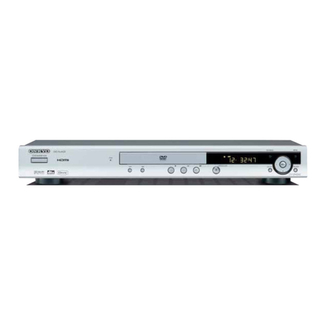
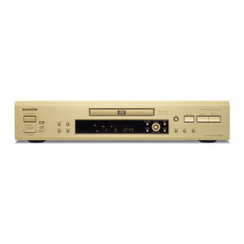
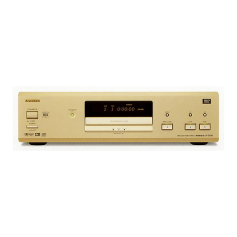
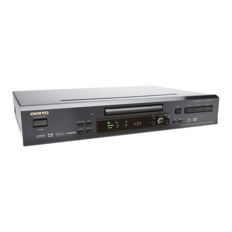
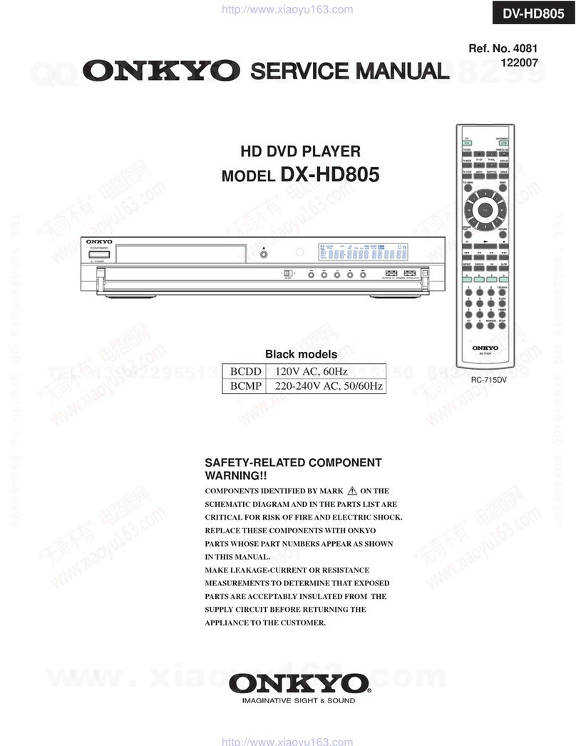
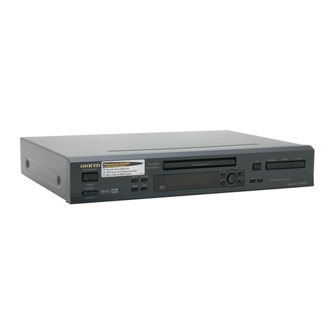
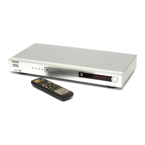
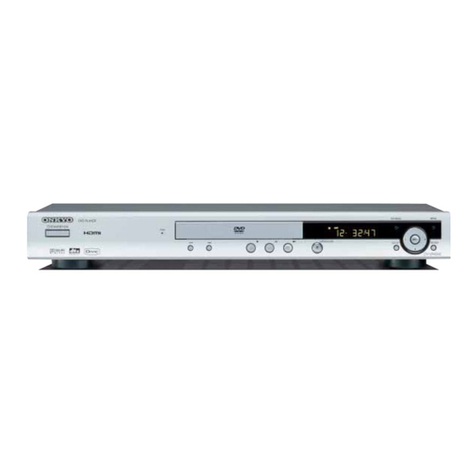
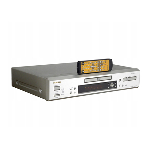
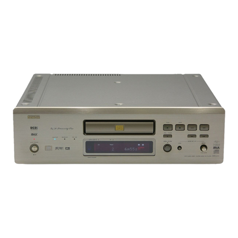
Onkyo DV-L5 User manual

DV-L5
Ref. No. 3695
082001
DVD Player
DV-L5
MDD 120V AC, 60Hz
MUP, MUT,
MUS, MUR 100 - 240V, 50/60Hz
Silver and Titanium color models
LAST M COND.M DIMMER DISPLAY
STANDBY
ON
ANGLE AUDIO
SUBTITLE
MENU
TOP MENU
SETUP
RETURN
STOPPAUSE
FUNCTION M
OPEN/CLOSE
DOWN UPFR FF
CLEAR
PROGRAM
RANDOM REPEAT A-B
STEP/SLOW
SEARCH
REMOTE CONTROLLER RC-
449
DV
PLAY
23
456
789
1
0
+
10
+
-
ENTER
TV
ON/STANDBY
VOL+
VOL
-
TV/VCR
CH+
CH
-
TVDVD
LAST M COND.M DIMMER DISPLAY
STANDBY
ON
ANGLE AUDIO
SUBTITLE
MENU
TOP MENU
SETUP
RETURN
STOPPAUSE
FUNCTION M
OPEN/CLOSE
DOWN UPFR FF
CLEAR
PROGRAM
RANDOM REPEAT A-B
STEP/SLOW
SEARCH
REMOTE CONTROLLER RC-
450
DV
PLAY
23
456
789
1
0
+
10
+
-
ENTER
TV/VCR
RC-449DV
<MDD> RC-450DV
<MUP,MUT,
MUS,MUR>

DV-L5
SERVICE NOTE
1. Replacing the fuses 2. Safety-check out
(Only U.S.A. model)
After correcting the original service problem perform the
following safety check before releasing the set to the customer
Connect the insulating-resistance tester between the plug of
power supply cord and terminal GND on the back panel.
Specifications: More than 10M ohm at 500V
REF.NO. PART NO. DESCRIPTION
F1 2522152 or 1.6A-T/UL-ST2 or
2522147 1.6A-TSC, Fuse <MDD>
This symbol located near the fuse indicates that the
fuse used is show operating type, For continued protection against
fire hazard, replace with same type fuse , For fuse rating, refer to
the marking adjust to the symbol.
Ce symbole indique que le fusible utilise est e lent.
Pour une protection permanente, n'utiliser que des fusibles de meme
type. Ce demier est indique la qu le present symbol est apposre.
252273 or 1.6A-SE-TL250V or
252077 1.6A-SE-EAK Fuse
TO REDUCETHE RISK OF FIRE OR ELECTRIC SHOCK, DO NOT EXPOSETHIS APPLIANCETO RAIN
OR MOISTURE. DANGEROUS HIGHVOLTAGES ARE PRESENT INSIDETHE ENCLOSURE. DO NOT OPENTHE
CABINET. REFER SERVICINGTO QUALIFIED PERSONNEL ONLY.
TO PREVENT ELECTRIC SHOCK, MATCHWIDE BLADE OF PLUGTOWIDE SLOT, FULLY INSERT.
POUR EVITER LES CHOCS ELECTRIQUE, INTRODUIRE LA LAME LA PLUS LARGE DA LA FICHE DANS LA
BORNE CORRESPONDANTE DA LA PRISE ET POUSSER JUSQU' AU FOND.
WARNING :
CAUTION :
ATTENTION :
The lightning flash with arrowhead symbol, within an equilateral triangle, is
intended to alert the user to the presence of uninsulated "dangerous voltage"
within the product's enclosure that may be of sufficient magnitude to constitute
a risk of electric shock to persons.
The exclamation point within an equilateral triangle is intended to alert the user
to the presence of important operating and maintenance (servicing) instruction
in the literature accompanying the appliance.
<MUP,MUS,MUT,MUR>
1.Ground for the work-desk.
Place a conductive sheet such as a sheet of copper (with impedance lower than 10Mohm) on the work-desk and
place the set on the conductive sheet so that the chassis.
2.Grounding for the test equipments and tools.
Test equipments and toolings should be grounded in order that their ground level is the same the ground of the power source.
3. Grounding for the human body.
Be sure to put on a wrist-strap for grounding whose other end is grounded.
Be particularly careful when the workers wear synthetic fiber clothes, or air is dry.
4. Select a soldering iron that permits no leakage and have the tip of the iron well-grounded.
5. Do not check the laser diode terminals with the probe of a circuit tester or oscilloscope.
PRECAUTIONS
LASER CAUTION

DV-L5
SERVICE NOTES
1. Remove the solder of Laser Diode shorting
1-1 Connect Pickup and DVD main circuit PC board by FFC(3 pcs).
1-2 Fix it with the DVD Mecha
1-3 Remove the solder of Laser Diode shorting on Pickup.
1-4 Connect total unit of DVD Mechanism (DVD Main PCB + Mechanism) to output terminal.
PC board (NCAR7181) at CN102 and CN106
2. Check the FL display
Press the [STOP] and [DISPLAY] keys at the same time .
FL display light up, and check the FL display.
To cancel this process, Please press the [STOP] and [DISPLAY] keys at the same time again.
3. Factory setting
3-1 Push the power switch "ON" (Mechanical switch)
3-2 Press the [STOP] and [POWER ON] keys at same time (Wait for until FL display "No Disc") .
3-3 Standby button is "OFF".
Rear View
Short
DVDM Assy
Side
Short SW
Open

DV-L5
Specifications and features are subject to change without notice.
DVD Player
Power supply USA and Canadian models: AC 120 V, 60 Hz
Other models: AC 100 -240 V , 50/60 Hz
Power consumption USA and Canadian models: 13 W
Other models: 12 W
Weight 3.7 kg, 8.2 lbs.
External dimensions USA and Canadian models:
435 81 353.5 mm (W/H/D), 17-1/8"3-3/16" 13-15/16"
Chinese models: 435 81
361 mm (W/H/D)
Other models: 435 81 359 mm (W/H/D)
Signal system USA and Canadian models: NTSC
Other models: PAL/NTSC
Regional restriction code USA and Canadian area: 1
South-east Asian area: 3
Australian and South American area: 4
PRC: 6
Laser Semiconductor laser, wavelength 650 nm
Frequency range (digital audio) DVD linear sound: 48 kHz sampling 4 Hz to 22 kHz
96 kHz sampling 4 Hz to 44 kHz
Audio CD: 4 Hz to 20 kHz
Signal-to-noise ratio (digital audio) More than 100 dB
Audio dynamic range (digital audio) More than 96 dB
Harmonic distortion (digital audio) Less than 0.015 %
Wow and flutter Below measurable level (less than ±0.001 % (W.PEAK))
Operating conditions Temperature: 5 C to 35 C (41 F to 95 F), Operation status: Horizontal
Outputs
Video output 1.0 V (p-p), 75 ohm, negative sync., pin jack 1
S-video output (Y) 1.0 V (p-p), 75 ohm, negative sync., Mini DIN 4-pin 1
(C) 0.286 V (p-p), 75 ohm
Component video output (Y) 1.0 V (p-p), 75 ohm, negative sync., pin jack 1
(PB)/(PR) 0.7 V (p-p), 75 ohm,
pin jack 2
Audio output (digital output Optical) -22.5 dBm 1
Audio output (digital output Coaxial) 0.5 V (p-p), 75 ohm, pin jack 1
Audio output (2-Channel Audio) 2.0 V (rms), 470 ohm, pin jack (L, R, MONO) 1
SPECIFICATIONS
European area: 2

DV-L5
POWER switch
Turns on the main power supply for the DV-L5. The DV-L5 enters
standby state. Pressing the switch again to the off position (
OFF) shuts down the main power supply into the DV-L5.
Before turning on the power, make sure all cables are properly
connected.
STANDBY/ON button / STANDBY/ON indicator
When STANDBY/ON button is pressed to ON while the POWER
switch is set to ON, the DV-L5 turns on. The STANDBY indicator
turns off and the ON indicator lights up. Pressing the button again
returns the DV-L5 to the standby state. This state turns off the
display, disables control functions.
Disc tray
When loading a disc, place discs in the disc tray with the label
side facing up.
Remote control sensor
Point the remote control toward the remote sensor to operate the
player.
Display
TOP MENU button
Press to call up the top menu programmed on the DVD.
Depending on the DVD, the top menu may be identical to the
DVD menu.
Cursor button/ENTER button
Use cursor button to move through the options on menu screens
and to change settings. Use ENTER to implement settings
selected with the cursor buttons or to set items highlighted in a
menu.
MENU button
Use to display or close the DVD menu or MP3 Navigator screen.
button
Press to stop playback. Pressing once enables playback to
resume from a point shortly before the location where it stopped.
Pressing twice causes the disc to return to the beginning of the
disc if playback starts again.
button
Press to start or resume playback.
button
Press to open and close the disc tray.
CLEAR button
Works in conjunction with a number of player functions. Use to
cancel repeat and random playback, and to edit programs.
REPEAT button
Use to set the repeat mode.
RANDOM button
Press to play chapters/tracks in random order.
LAST MEMORY button
You can resume DVD or Video CD playback from the point you
last watched even if the disc is removed from the player. Press
LAST MEMORY during playback to set a Last Memory point.
When you want to resume playback of that disc, press LAST
MEMORY in the stop mode and playback starts from the
memorized point. Last Memory locations can be stored for up to 5
DVDs and 1 Video CD.
DISPLAY button
Press during playback to display statistical disc information.
Press repeatedly to display different information.
/button
Press to go back or advance to previous chapters/tracks. Press
and hold to perform fast-reverse/fast-forward playback scanning.
RETURN button
Use to go one menu back (current settings are maintained). Use
RETURN when you do not want to change the option setting in a
menu.
SETUP button
Press when the player is in either play or stop mode to open and
close the Setup screen.
button
Press during playback to pause. Press again to resume playback.
FRONT PANEL
PANEL VIEW

DV-L5
TITLE CHAPTER TRACK REMAIN
LAST
COND.
DTS
REPEAT
DVD VC D
D
GUI
L
MONO
R
VIDEO OUTPUT
Y
C
B
C
R
OPTICAL COAXIAL
REMOTE
CONTROL
ANALOG
OUTPUT
DIGITAL
OUTPUT
VIDEO S VIDEO
COMPONENT
W
/indicator
Inserted disc indicator
TITLE indicator
Angle icon indicator
CHAPTER/TRACK indicator
REPEAT indicator
REMAIN indicator
LAST indicator
COND. indicator
D indicator
DTS indicator
GUI indicator
Multifunctional indicator
(e.g. operating status and error messages)
VIDEO OUTPUTVIDEO jack
Connect to the video input on a TV or monitor orAV amplifier or
receiver with video input capability.
VIDEO OUTPUT SVIDEO jack
If your TV or monitor has an S-video input, clear picture
reproduction is possible by connecting the player to your TV or
monitor via the S-Video jack.
You can switch between [S1] and [S2] S-video output from the
Setup menu.
VIDEO OUTPUT COMPONENT jacks
If your TV or monitor has component video inputs, you can
produce a higher quality picture on your TV or monitor by
connecting to the component video outputs on this unit.
ANALOG OUTPUT jacks
Use to output two-channel audio (analog) to the audio stereo
inputs on a TV or stereo amplifier. If you are connecting to a
receiver that has both digital and analog input jacks for DVD
player connection, it may be beneficial to make both connections.
DIGITAL OUTPUT OPTICAL jack
Use to output the digital audio signal recorded on discs. You can
output the digital signal via the optical output jack to an AV
amplifier or receiver.
DIGITAL OUTPUT COAXIAL jack
Use to output the digital audio signal recorded on discs. You can
output the digital signal via the coaxial output jack to an AV
amplifier or receiver.
jack
Use to connect this player to another component bearing the
mark. This lets you control this unit as though it were a
component in a system.
AC OUTLET
The AC power cord of another component can be connected to
this AC OUTLET connector.
This means that if the DV-L5 is plugged into an AC outlet, AC
power is available to this AC OUTLET even if the DV-L5 is off.
The shape and capacity of the AC outlet may differ depending on
the area of purchase. Make sure that the capacity of other
components connected to this unit does not exceed the capacity
that is printed on the rear panel.
PANEL VIEW 1
DISPLAY
REAR PANEL <MDD>

DV-L5
REAR PANEL <MUP/MUT/MUS/MUR>
AV CONNECTOR <MUP> only
Use a 21-pin SCART cable to connect to a TV or monitor
compatible with this type of connection. Both audio (2 channel
stereo) and video (Video, S-video, and RGB) signals are output
from the AV CONNECTOR.
VIDEO OUTPUTVIDEO jack
Connect to the video input on a TV or monitor orAV amplifier or
receiver with video input capability.
VIDEO OUTPUT SVIDEO jack
If your TV or monitor has an S-video input, clear picture
reproduction is possible by connecting the player to your TV or
monitor via the S-Video jack.
You can switch between [S1] and [S2] S-video output from the
Setup menu.
ANALOG OUTPUT jacks
Use to output two-channel audio (analog) to the audio stereo
inputs on a TV or stereo amplifier. If you are connecting to a
receiver that has both digital and analog input jacks for DVD
player connection, it may be beneficial to make both connections.
DIGITAL OUTPUT OPTICAL jack
Use to output the digital audio signal recorded on discs. You can
output the digital signal via the optical output jack to an AV
amplifier or receiver.
DIGITAL OUTPUT COAXIAL jack
Use to output the digital audio signal recorded on discs. You can
output the digital signal via the coaxial output jack to an AV
amplifier or receiver.
jack
Use to connect this player to another component bearing the
mark. This lets you control this unit as though it were a
component in a system.
AC OUTLET
The AC power cord of another component can be connected to
this AC OUTLET connector.
This means that if the DV-L5 is plugged into an AC outlet, AC
power is available to this AC OUTLET even if the DV-L5 is off.
The shape and capacity of the AC outlet may differ depending on
the area of purchase. Make sure that the capacity of other
components connected to this unit does not exceed the capacity
that is printed on the rear panel.
PANEL VIEW 2
DISPLAY
TITLE CHAPTER TRACK REMAIN
LAST
COND.
DTS
REPEAT
DVD VC D
D
GUI
/indicator
Inserted disc indicator
TITLE indicator
Angle icon indicator
CHAPTER/TRACK indicator
REPEAT indicator
REMAIN indicator
LAST indicator
COND. indicator
D indicator
DTS indicator
GUI indicator
Multifunctional indicator
(e.g. operating status and error messages)

DV-L5
REMOTE CONTROLLER (The illustration shows the RC-449DV remote controller.)
ON button
Press to switch the player on.
STANDBY button
Press to put the player in standby.
ANGLE button
Some DVDs are recorded with various camera angle playback
options. Press ANGLE repeatedly to display different camera
angles.
LAST MEMORY button
You can resume DVD or Video CD playback from the point you
last watched even if the disc is removed from the player. Press
LAST MEMORY during playback to set a Last Memory point.
When you want to resume playback of that disc, press LAST
MEMORY in the stop mode and playback starts from the
memorized point. Last Memory locations can be stored for up to 5
DVDs and 1 Video CD.
COND. M button
You can store in memory the settings for up to 15 DVDs. Press
COND. M during DVD playback to memorize the settings.
TOP MENU button*
Press to call up the top menu programmed on the DVD.
Depending on the DVD, the top menu may be identical to the DVD
menu.
Cursor buttons ( / / / )*
Use to move through the options on menu screens and to change
settings.
CH +/-, VOL +/- buttons (<MDD > only)
RETURN button*
Use to go one menu back (current settings are maintained). Use
RETURN when you do not want to change the option setting in a
menu.
TV/VCR button
PAUSE button
Press to pause playback of a disc. Press again to resume
playback.
STOP button
Press to stop playback. Pressing once enables playback to
resume from a point shortly before the location where it was
stopped. Pressing twice causes the disc to return to the beginning
of the disc when playback starts again.
FR/FF / buttons
During playback of DVD and Video CD, press to perform fast
forward scanning or to perform fast reverse scanning of DVD
and Video CD. When a CD or MP3 is loaded, audio scanning is
performed.
Number buttons (1-9, 0, +10)*
Use to perform direct title/folder and chapter/track searches, and
to input numerical values.
RANDOM button
Press to play chapters/tracks in random order.
REPEAT button
Use to set the repeat mode.
OPEN/CLOSE button
Press to open or close the disc tray.
SUBTITLE button
Press repeatedly to select one of the subtitle languages
programmed on a DVD or to turn the subtitles off.
AUDIO button
Press repeatedly to select one of the audio languages
programmed on a DVD.
For Video CD, CD and MP3, each press changes the audio
output as follows.
Stereo 1L(Left) 2/R(Right)
DISPLAY button
Press during playback to display statistical disc information.
Press repeatedly to display different information.
DIMMER button
Toggle to control the lightness of the display.
MENU button
Use to display or close the DVD menu or MP3 Navigator screen.
ENTER button*
Use to implement settings selected with the cursor buttons or to
set items highlighted in a menu.
SETUP button*
Press when the player is in either play or stop mode to open and
close the Setup screen.
PLAY button
Press to start or resume playback.
UP/DOWN /buttons
During playback, press to go back to a previous chapter/track
and to advance to the next chapter/track .
STEP/SLOW +/- buttons
Press STEP/SLOW + or - during playback to view still frame.
Press and hold STEP/SLOW + or - during playback to view slow
playback. In still frame, press STEP/SLOW + to advance DVDs
and Video CDs frame by frame and STEP/SLOW - to back up a
few frames at a time (DVD only).
FUNCTION M button
You can store in memory up to 5 settings. Press FUNCTION M to
memorize and recall the settings.
CLEAR button
Works in conjunction with a number of player functions. Use to
cancel repeat and random playback, and to edit programs.
SEARCH button
Press to perform a title/folder, chapter/track or elapsed time
search.
PROGRAM button
You can program titles, chapters, or tracks to play back in a
desired order. Programs can be a maximum of 24 steps.
Additionally, DVD programs for up to 24 discs can be stored in
the player's memory for future use.
A-B button
Press at the beginning and end of the section you want to repeat
or to mark a location you want to return to.
DVD/TV switch
(Buttons indicated with * are used for menu operation.)
LAST M COND.
M DIMMER DISPLAY
STANDBY
ON
ANGLE AUDIO
SUBTITLE
MENU
TOP MENU
SETUP
RETURN
STOPPAUSE
FUNCTION M
OPEN
/
CLOSE
DOWN UPFR FF
CLEAR
PROGRAM
RANDOM REPEAT A-B
STEP/
SLOW
SEARCH
REMOTE CONTROLLER RC-
449
DV
PLAY
23
456
789
1
0
+
10
+
-
ENTER
TV
ON
/
STANDBY
VOL
+
VOL
-
TV/
VCR
CH
+
CH
-
TVDVD
PANEL VIEW
1
2
34
56
7
8
9
10
11
12
13
14
15
16 17
18 19
20 21
22
23
24
25
26
27 28
29 30
31
(<MDD > only)
(<MDD > only)
1
2
3
4
5
6
7
8
9
10
11
12
13
14
15
16
17
18
19
20
21
22
23
24
25
26
27
28
29
30
31

EXPLODEDVIEW
DV-L5
A12
A01
A10
A04
A04
A10
A10
A27
A31
A28
A27
A28
A31
A20
A32
A04
A40
A38
A04
E701
A43
A43
A44
A45
A46
A49
A50
A50
A50
A50 A50
A50
A61
A61
A60
A63
A64
A04
A62
A51
A65
A66
A67
E702
E703
E901A
A04
F901
E903
A04
A04
A04
A07
A05
E904
F902
<MUT,MUR,
MUS> only
P904
P904
A25
A25
P982A
<MUR>only
A09
A09
A09
A09
A09
A09
<MUP> only
S731
U4
<MUP>
only
U6
A16
U10
U5
U11
A04A15 U1
A18
U7
A04
U3
A09
A09
A09
A09
U2
Z01A04
A03
A15
E704
<MUP>
only
A53
P904
A04

DV-L5
EXPLODED VIEW PARTS LIST
REF. NO. PART NO. DESCRIPTION REF. NO. PART NO. DESCRIPTION
A01 27100406 Chassis E701 2045161512 Flexible flat cable, NCFC5-161512
A03 27191145 Holder (DVD) E702 2045171512 Flexible flat cable, NCFC5-171512
A04 838130088 Self tapping screw, 3TTB+8B E704 2046200512 Flexible flat cable, NCFC6-200512
A05 27130868 Bracket <MUP>
A07 830440069 Self tapping screw, 4TTC+6C(BC) E703 2009990675UL Socket AS, NSAS-10P0939
A09 838430088 Self tapping screw, 3TTB+8B(BC) E901A 29362993 Fuse label, 1.6A/125V <MDD>
A10 27190524 Holder, KGLS-14RF 29361769 Fuse label, T1.6AL250V
A12 27190266 Holder, KGLS-12RF <MUP,MUT,MUR,MUS>
A15 27191154 Holder E903
260208 Wire tie
A16 27273191 Joint, POWER E904 27255004 Clip, CS-1U
A18 28325867 Knob, POWER <S> F901 252252 or Fuse, 1.6A-T/UL-ST2 or
28325868 Knob, POWER <T> 2522147 1.6A-TSC <MDD>
A20 29362648 Label, DVD2 252273 or Fuse, 1.6A-SE-TL250V or
A25 27300750 Bushing, #2271 1.6A-SE-EAK <MUP,MUT,MUR,MUS>
A27 27175316B Leg F902 252274 or Fuse, 2A-SE-TL250V or
A28 28141332 Cushion 252074 2A-SE-EAK <MUP,MUT,MUR,MUS>
A31 831430088 Self tapping screw, 3TTW+8B(BC) P904 253279HDK or Power cord, AS-UC-2#18 <MDD>
A32 27111232A Front bracket ass'y <S> 253279HIT
27111233A Front bracket ass'y <T> 253193HIT Power cord, AS-CEE <MUP,MUT,MUS>
A38 838426088 Self tapping screw, 2.6TTB+8B(BC) 253286VOL or Power cord, AS-CCEE <MUR>
A40 28325943 Knob, JOY STICK <S> 253267KAW or
28325944 Knob, Joy stick <T> 253285HIT
A43 29110161 Tape P982A 27191130 Holder, Outlet <MUR>
A44 28148483 Door <S> S731 25035710 Joy stick switch, NPS-115-S673
28148484 Door <T> U1 1H475597-1A Output terminal PC board ass'y,
A45 27262651 Plate, DVD NAAR-7197-1A <MDD>
A46 28325939 Knob ass'y, PAUSE <S> 1H475597-1B Output terminal PC board ass'y,
28325940 Knob ass'y, PAUSE <T> NAAR-7197-1B <MUT>
A49 28184822 Top cover 1H475597-1E Output terminal PC board ass'y,
A50 838930088 Self tapping screw, 3TTB+8B(UN) NAAR-7197-1E <MUP>
A51 28141390 Cushion 1H475597-1F Output terminal PC board ass'y,
A53 29363012 Label, RISK NAAR-7197-1F <MUR>
A60 27122876A Rear panel <MDD> 1H475597-1C Output terminal PC board ass'y,
27122878 Rear panel <MUT> NAAR-7197-1C <MUS>
27122880 Rear panel <MUR> U2 1H475598-1A Display circuit PC board ass'y,
27122879 Rear panel <MUS> NADIS-7198-1A <MDD>
27122877A Rear panel <MUP> 1H475598-1B Display circuit PC board ass'y,
A61 28141467 Cushion NADIS-7198-1B <MUT>
A62 27212335 Front panel <S> 1H475598-1E Display circuit PC board ass'y,
27212336 Front panel <T> NADIS-7198-1E <MUP>
A63 28198930 Facet, STANDBY <S> 1H475598-1F Display circuit PC board ass'y,
28198930 Facet, STANDBY <T> NADIS-7198-1F <MUR>
A64 27268047 Guide, STANDBY <S> 1H475598-1C Display circuit PC board ass'y,
27268048 Guide, STANDBY <T> NADIS-7198-1C <MUS>
A65 27268045 Guide, STOP <S> U3 1H475599-1A Standby LED PC board ass'y,
27268046 Guide, STOP <T> NADIS-7199-1A <MDD>
A66 28198928 Facet, STOP 1H475599-1B Standby LED PC board ass'y,
A67 28191934 Clear plate <S> NADIS-7199-1B <MUT>
28191935 Clear plate <T> 1H475599-1E Standby LED PC board ass'y,
NADIS-7199-1E <MUP>
1H475599-1F Standby LED PC board ass'y,
NADIS-7199-1F <MUR>
1H475599-1C Standby LED PC board ass'y,
NADIS-7199-1C <MUS>
DV-L5
EXPLODED VIEW PARTS LIST
REF. NO. PART NO. DESCRIPTION
U4 1H475500-1E SCART connection terminal
<MDD> :North American area (Regional restriction code- 1)
PC board ass'
y
, NAVD-7200-1E <MUP
>
<MUP> :European area (Regional restriction code- 2)
U5 1H475501-1A Outlet terminal PC board ass'y,
<MUT> :Some Asian area (Regional restriction code- 3)
NAPS-7201-1A <MDD>
<MUR> :Chinese area (Regional restriction code- 6)
1H475501-1B Outlet terminal PC board ass'y,
<MUS> :South American area (Regional restriction code- 4)
NAPS-7201-1B <MUT>
<S> :Silver color model
1H475501-1E Outlet terminal PC board ass'y,
<T> :Titan color model
NAPS-7201-1E <MUP>
1H475501-1F Outlet terminal PC board ass'y,
NAPS-7201-1F <MUR>
1H475501-1C Outlet terminal PC board ass'y,
NAPS-7201-1C <MUS>
U6 1H475502-1A Power switch PC board ass'y,
NASW-7202-1A <MDD>
1H475502-1B Power switch PC board ass'y,
NASW-7202-1B <MUT>
1H475502-1E Power switch PC board ass'y,
NASW-7202-1E <MUP>
1H475502-1F Power switch PC board ass'y,
NASW-7202-1F <MUR>
1H475502-1C Power switch PC board ass'y,
NASW-7202-1C <MUS>
U7 1H475503-1A Connection PC board ass'y,
NAETC-7203-1A <MDD>
1H475503-1B Connection PC board ass'y,
NAETC-7203-1B <MUT>
1H475503-1E Connection PC board ass'y,
NAETC-7203-1E <MUP>
1H475503-1F Connection PC board ass'y,
NAETC-7203-1F <MUR>
1H475503-1C Connection PC board ass'y,
NAETC-7203-1C <MUS>
U10 24150020 Power supply unit ass'y,
NGPS-0020-120V <MDD>
24150021 Power supply unit ass'y, NGPS-0021-
100V 240V <MUP,MUT,MUR,MUS>
U11 24150023 Main circuit PC board ass'y,
DB-VPB303
Z01 24801010 DVD mechanism, DB-VLD301-006
NOTE:THE COMPONENTS IDENTIFIED BY MARK
ARE CRITICAL FOR RISK OF FIRE AND
ELECTRIC SHOCK. REPLACE ONLY WITH
PART NUMBER SPECIFIED.
-

DV-L5
EXPLODED VIEW (LOADING MECHANISM)
A
To DVDM
CN151
2
8
8
8
12
23 13
17
16
15
14
20
18
19
91
11 10
6
8
Lubricating Oil
GYA1001
Daifree
GEM1036
Lubricating Oil
GYA1001
LOADING MECHANISM ASSY PARTS LIST
REF.NO PART NO. DESCRIPTION
1 VNP1836 Loading PC board assy
2 VXX2782 Traverse mechanism assy-S
6 VDA1864 Flexible cable 26P
8 VEB1327 Float rubber
9 VEB1328 Belt
10 VNE2253 Stabilizer
11 VNL1917 Loading base
REF.NO. PART NO. DESCRIPTION
12 VNL1918 Float base DVD
13 VNL1919 Drive cam
14 VNL1921 Gear pulley
15 VNL1922 Loading gear
16 VNL1923 Drive gear
17 VNL1925 SW lever
18 VNE2251 Clamper plate
19 VNE2252 Bridge
20 VNL1924 Clamper
23 VNL1920 Tray

DV-L5
MD-2000
P250B
P251A
U4: SCART connection
terminal PC board
NAETC-7382
U12:digital out terminal
PC board
NAVD-7204
JL601A
U1: Output terminal PC board
NAAR-7197
CN102 P701A
P711
CN106
P901
P351B
P356A
P250A
JL601B
P351A
JL711A
P701B
P731
U2: Display circuit PC board NADIS-7198
JL771B
U3: Standby LED
PC board
U6: Power switch
PC board
P991A
P992A
BRN U10: Power supply unit
CN2
NGPS-0020-120V <MDD>
NGPS-0021-100-240V
<Others model>
AC-H
AC-G
U5: Outlet terminal PC board
NAPS-7201
AC-H
AC-G
P991B
P992C
WHT
NAVD-7200
P001
P002
P003
U7: Connection
PC board
PRINTED CIRCUIT BOARD CONNECTION DIAGRAM
WHT
ORG
CN15
CN401
CN51
CN61
CN151
DB-VPB303
<MPP> only
<MJJ> only
RC-232C connecting
PC board
P356B
To Joy switch
Z01: DVD mechanism
DB-VLD301-006
NAPS-7202
NADIS-7199
<MJJ> only
U11: Main circuit
PC board

DV-L5
A
1
2
3
4
5
BCDEFGH
P356A
P356B
D223
1SS226
12
D222
1SS226
12
D223
1SS226
23
D222
1SS226
23
D221
1SS226
23
D221
1SS226
12
Q902 025EZ5M
GND
1
NC
2
ON/OFF
4
VIN
5
VOUVOUT
3
P250A
P701A
P901
P202
1
2
3
4
5
7
JL601B
P711
P401
2
3
1
4
P203
2
3
1
4
D403
D401
NC
D402
NC
Q405
HN1C03F
26
1
Q405
HN1C03F
53
4
Q403
HN1C03F
53
4
Q403
HN1C03F
2
6
1
Q404
HN1C03F
2
6
1Q404
HN1C03F
53
4
D901
UDZS5.1B
Q901
78M08
G
IO
Q301
PCM1742KE
AGND
9
BCKIN1DATA2
GND4LRCKIN3MC14
MCLK
16
MD13
ML15
VCC6
VCOM
10
VDD5
VOUTL7VOUTR8
ZEROL
12
ZEROR
11
P104
CTS 4
DTR 3
GNDD 6
NC 7
RXD 2
TXD 1
V+5D 5
Q452
NC
Q412
2SA1162
Q411
NC
CN106
6CH/X2CH12
ADATA0 7
ADATA1 9
ADATA211
ADATA313
B/CB25
BCK 3
C28
G/Y27
GND1 1
GND2 4
GND318
GND420
GND522
GND624
LFE_ON16
LRCK 5
MCLK 2
P/XI[VSEL2]17
PRG_CB21
PRG_CR19
PRG_Y23
R/CR29
V26
VSEL115
XCSDF 6
XMUTE14
XSCK 8
XSI10
Y30
CN102
+12VM 9
+2.5V112
+2.5V213
+3.3V1 8
+3.3V210
AODAI26
CTS18
DTR20
GND1 4
GND2 6
GND311
GND414
GND515
GNDM1 5
GNDM2 7
LETTER30
LT119
M+6V1 1
M+6V2 3
MICON117
MICON216
RXD22
SCK27
SQUEEZE28
SW5V 2
S[FTOM]23
S[MTOF]25
TXD24
XREADY29
XRESET21
Q401
NJM4565M-D
5
6
-B
47
Q402
NJM4565M-D
5
6
-B
4
7
Q401
NJM4565M-D
3+B
8
21
Q402
NJM4565M-D
3+B
8
21
P351BP351A
Q353
GP1FA551RZ
OPTICALOUT2
1
3
2
Q352
GP1FA551RZ
OPTICAL_OUT
1
3
2
Q351
TC74VHCU04T
1
2
3
4
5
68
9
10
11
12
13
GND7
VCC14
Q451
NC
Q410
RN1407
Q302
NC
Q303
RN1407
Q419
NC
Q202
RN1407
Q204
RN1407
Q203
RN2403
Q205
RN2403
Q201
MM1540BF
CBIN
11 CBOUT 18
CIN
4CLP
5COUT 25
CRIN
13 CROUT 16
DUAL
12
GND
10
MUTE1
7MUTE2
8
PS1 26
PS2 17
VCC1
1 VCC2 28
VEE1
14 VEE2 15
VEE3 19
VEE4 21
VEE5 22
VEE6 24
VIN
2VOUT27
YCMIX
3
YIN1
6
YIN2
9
YOUT1 23
YOUT2 20
C362
020
C359
223Z
C360
223Z
C306
104Z
C414
102
C451
C915
104Z
C901
104Z
C351
104K
C219
104K
C361
020
C225
104Z
C405
221
C403
102
C407
330
C413
102
C356
104Z
C202
104Z
C418
102
C302
104Z
C304
104Z
C914
104Z
C352 104Z
C354
104K
C355
220
C357
C905
104Z
C907
104Z
C216
104Z
C909
104Z
C903
104Z
C101
104Z
C417
C408
330
C406
221
C404
102
C203
104Z
C204
104K
C206
104K
C207
104K
C209
104K
C211
104K
C213
104K
C365
100/6.3
C305
100/6.3
C415
22/50
C902
220/16
C218
470/6.3
C217
470/6.3
C401
22/50
C411
22/50
C409
100/16
C358
100/6.3
C201
100/16
C301
100/6.3
C303
100/6.3
C452
C353 100/6.3
C906
220/16
C908
220/6.3
C215
47/16
C913
47/16
C911
100/16
C912
100/16
C910
220/6.3
C904
220/6.3
C402
22/50
C410
100/16
C412
22/50
C205
C208
C210
10/16
C212
C214
C220
470/6.3
C222
470/6.3
C221
470/6.3
L353
BK1608LM182-T
L203
L202
L201
L351 BK1608LM182-T
L352
BK1608LM182-T
L204
L206
L205
R356
470
R457
0
R458
0
R301
220
R458
R425
470
R426
470
R232 R231
R457
R422
2.2K
R418
2.2K
R453
R452
R442
1K
R101
10K
R357
0
R206
10K
R210
R209
75
R208
R207
75
R205
R204
75
R455
220
R454
220
R428
100K
R430
2.2K
R429
2.2K
R202
1K
R403
R415
220
R409
33K
R407
10K
R405
15K
R401
2.2K
R411
0
R413
100K
R441
1K
R419
220 R423
1K
R421
2.2K
R417
2.2K
R451
R432
1.8K
R436
R438
4.7K
R434
1K
R433
1K
R901
0
R117 47
R116 47
R115 47
R113 47
R114 47
R112 47
R109 47
R108 47
R111 47
R110 47
R107 47
R106 47
R105 47
R104 47
R102 47
R103 47
R134 10K
R133 10K
R132 10K
R131 10K
R213
R216
R221
R351 100K
R352 470K
R354
180
R355
180
R353
330
R431
R902
10K
R118 47
R119 47
R120 47
R121 47
R122 47
R123 47
R124 47
R125 47
R126 47
R127 47
R128 47
R129 47
R130 47
R435
R437
R410
33K
R408
10K
R404
R406
15K
R402
2.2K
R412
0
R416
220 R420
220
R414
100K
R424
1K
R203
0
R201
1.5K
R212
75
R211
0
R223
560
R222
470
R220
100
R219
0
R218
560
R217
470
R215
100
R214
0
P201
P353
COAXIAL_OUT
P354
RI_OUT
1
2
3
4
SW+5V
SCK
SI
SO
VPP
XREADY SQUEEZE
M_RESET
P_ON
XRESET
RI
LT LETTER
GND
GND GND
EVER+5V
-27V
DOUT
FLAC1
FLAC2
V V+8V
C
MCLK
BCK
LRCLK Y
XCSDF
ADATA0
XSCK G/Y
XSI
B/CB
XMUTE
VSEL1
SI
SO
SCK
M_RESET
VPP
VSEL2 R/CR
V+12V
VSEL1
B/CB C1
VSW+5V VSEL2
G/Y Y1
C
R/CR V1
YV+12V G1
B1
R1
XRESET XMUTE SQUEEZE
CTS
LT
DTR
AGND
V+6A
V+12V
XRESET
RXD
BCK MCLK
SO
ADATA0 XCSDF
TXD
LRCLK XSCK
SI
XSI
DOUT
SCK
SQUEEZE
XREADY
LETTER
TXD
RXD
-27V
FLAC1
FLAC2
P_ON
EVER+5V
GND
M+6V
MGND
V+12V
GND
SW+5V
GND
+3.3V
GND
DTR
CTS
<MJJ> Only
NAETC-7382
+8V
+12V
+5V
+3.3V
+5V
+2.5V
TO NAVD-7204
TO NAVD-7200
V+12V
VSEL1
C
VSEL2
Y
GND
V
GND
G
GND
B
R
GND
GND
+5V
AUDIO_L
GNDA
AUDIO_R
MONO
R
SQUEEZE
V+8V
17
20
19
18
16
15
14
13
12
11
10
9
8
7
6
5
4
3
1
2
NAAR-7197
for FL Micon DL
CB
CR
Y
GND
GND
GND
GND
SW
L
CR
GND
CB
Y
For Download
1mm Pich FFC
U1: Output terminal PC board
To Power supply unit
To Main PC board CN-15
To Main PC board CN-401
To Display circuit PC board NADIS-7198
SCHEMATIC DIAGRAM-1
<MUP> only

DV-L5
A
1
2
3
4
5
BCDEFGH
P701B
R785
D702
UDZS5.6B
D701
1SS352
Q704
RN2403
Q705
REMOTE
SENSOR
Q703
BMR-0101D
GI
O
X701
5.00MHZ
C703
22/50
C704
100/6.3
C701
100/6.3
C706
223Z
C702
104Z
P731
ENTER
S731
NPS-115-S673
5
3
4
2
1
6
7
JL771B
JL771A
S708
OPEN
S707
UP
S706
DOWN
S709
PAUSE
S710
STOP
S711
PLAY
S712
CLEAR
S713
RANDOM
S714
REPEAT
S715
MEMORY
S705
DISPLAY
S701
T.MENU
S702
MENU
S703
SETUP
S704
RETURN
S723
STANDBY
R788
10K
R786 R787
R758
100
R714
4.7K
R7590
R711
0
R709
0
R710
0
R712
0
R713
0
R782
10K
R701
1M
R702 0
R703 0
R704 0
R705 0
R706 0
R707 0
R717 2.7K
R718 2.7K
R719 2.7K
R754
100
R721R720
R722 R723
R724 R725
R727R726
R730
470
R731
470
R732
470
R716 220KR715
47K
R745
3.9K
R746
10K
R738
3.9K R739
10K
R747
390
R748
470
R749
820
R750
1K
R744
1.8K
R737
1.8K
R733
390 R734
470 R735
820
R740
390
R741
470
R742
820
R743
1K
R736
1K
R774
R773
R771
1.8K
R772
3.9K
Q708
RN1407
Q707
RN1407
Q706
RN1407
Q722
RN1407
Q721
RN1407
D705
PLAY_LED
D704
STOP_LED
D703
OPEN_LED
D721
STANDBY
D722
POWER
Q701
MPD780232GC
+5V 24
10G71
11G70
12G69
13G68
14G
67
192LED41
1G80
2G79
3G78
4G77
5G76
6G75
7G74
8G
73
96LED42
9G72
GND1 5
GND2 18
INIT1 19
IRIN 15
K0 22
K1 21
K2 20
LEDO46
LT1 16
MSO_0 38
MSO_1 37
MSO_2 36
NC1 13
NC2 14
NC3 34
NC4 35
NC547
NC648
NC7
49
OPCLED45
P166
P1055
P1154
P1253
P1352
P1451
P1550
P265
P364
P463
P562
P661
P758
P857
P956
PLYLED43
PON 11
R232BUSY 29
R232REQ 28
R232SCK 31
R232SI 30
R232SO 32
RESET 6
SI 8
SO 9
STBYLED 39
STPLED44
SYSIN 26
SYSOUT 27
SYSRESET 12
TEST 33
VCOFF 17
VDD0 25
VDD1 1
VDD2
59
VLED
40
VLOAD60
VSS0 23
VSS1 2
X1 4
X2 3
XRDY 10
XSCK 7
Q702FL-545
10G14
11G15
12G16
13G17
14G18
1G 5
2G 6
3G 7
4G 8
5G 9
6G 10
7G 11
8G 12
9G 13
F1 48
F2' 1
P1 30
P10 39
P11 40
P12 41
P13 42
P14 43
P15 44
P2 31
P3 32
P4 33
P5 34
P6 35
P7 36
P8 37
P9 38
PAU_L
STP_L
PLY_L
K0
POW_L
STB_L
K1
MSO_0
MSO_1
MSO_2
INIT1
K0
K1
K2
REMO
STB_L
MSO_0
MSO_1
MSO_2
SYSOUT
SYSIN
K0
K1
K2
SYSIN
K2 RI
INIT1
PLY_L SYSOUT
STP_L
LT1
RI
RESET
PON
XRDY
SO
SI
XSCK
LT1
REMO
PAU_L
POW_L RESET
P15 PON
P14 XRDY
FLAC2
FLAC1
-27V
E+5V
GND
GND
LT1_1
RI
RESET
PON
M-RESET
XRDY
VPP
SO
SI_1
XSCK
P13 SO
M-RESET
VPP
P12 SI
P11 XSCK
P10
P9
P8
P7
P6
P5
P4
P3
P2
P1
14G
13G
12G
11G
10G
9G
8G
7G
6G
5G
4G
3G
2G
1G
P15
P14
P13
P12
P11
P10
P9
P8
P7
P6
P5
P4
P3
P2
P1
14G
13G
12G
11G
10G
9G
8G
7G
6G
5G
4G
3G
2G
1G
TO NAAR-7197
NADIS-7198
U3: Standby LED PC board
NADIS-7198
Joy switch
U2: Display circuit PC board
SCHEMATIC DIAGRAM (2)
MARKBY
THE COMPONENTS IDENTFIED ARE CRITICAL FOR SAFETY.
REPLACE ONLY WITH PART NUMBER SPECIFIED.
.
.VOLTAGE (MEASUREDWITH VOLTMETER IS DCVOLTAGE. (NO INPUT SIGNAL)
.ELECTROLYTIC CAPACITORS ( )ARE IN F/WV.
.ALL CAPACITORS ARE IN pF/50WV UNLESS OTHERWISE NOTED.
EX) 030 3pF 330 33pF 331 330pF 333 0.033uF
u
ALL RESISTORS ARE IN OHMS 1/4WATTS UNLESS OTHERWISE NOTED.
.THE THICK LINES ON PC BOARD ARE THE PRINTING SIDE OF THE PARTS.
EX) PRINTING SIDE
CIRCUIT IS SUBJECT TO CHANGE FOR IMPROVEMENT.
.
.
NOTE
R720 56k 33k 68k 0 33k 8.2k
R721 56k 5.6k 6.8k 0 5.6k NC
R724 NC NC NC NC NC 1k
MDD MUT MUS MJJ MUR MUP
*

DV-L5
A
1
2
3
4
5
BCDEFGH
DV-L5
E LENT. POUR UNE PROTECTION PERMANENTE,N'UTILISER
CE SYMBOLE INDIQUE QUE LE FUSIBLE UTLISE EST
INDIQUE LA QU LE PRESENT SYMBOL EST APPOSE.
QUE DES FUSIBLES DE MEME TYPE. CE DARNIER EST
RATING REFER TO THE MARKING ADJACENT TO THE SYMBOL
FOR CONTINUED PROTECTION AGAINST FIRE
HAZARD,REPLACE WITH SAME TYPE FUSE. FOR FUSE
THIS SYMBOL LOCATED NEAR THE FUSE INDICATES
THAT THE FUSE USED IS SLOW OPERATING TYPE
ATTENTION
VA
ET CALIBRATION COMME INDIQUE.
D'INCENDIE, REMPLACER UNIQUEMENT
PERMANENTE CONTRE LES RISQUES
AFIN D'ASSURER UNE PROTECTION
PAR UN FUSIBLE DE MEME TYPE
VA
AGAINST FIRE HAZARD, REPLACE
FOR CONTINUED PROTECTION
AND RATING INDICATED.
ONLY WITH FUSE OF SAME TYPE
CAUTION
S991
P992A P991A P991B P992C
F901
T2AL250V
P981
P992
P982
P904
P250B
P602
JL601A
P251A
SCART
10
12
2
20
6
AGND4
AUDIO_L3
AUDIO_R1
B7
CV/Y19
F.SW8
G11
R/C15
RGB.SW16
VGND15
VGND29
VGND313
VGND414
VGND517
VGND618
VGND7
21
E201
D252
1SS226
23
D252
1SS226
12
D251
1SS226
23
D251
1SS226
1 2
L601
L
L602
L
L254
BK1608LM182-T
L251
BK1608LM182-T
L252
BK1608LM182-T
L253
BK1608LM182-T
Q258
RN1402
Q252
TC74HCT00AF
1
2
3
4
5
6
8
9
10
11
12
13
GND7
VCC14
Q251
TC4053BF
A11
B10
C9
EN6
GND8
VCC16
VEE7
X14
X012
X113
Y15Y02
Y11
Z4
Z05
Z1
3
C254
100/6.3
C258
470/6.3
C255
470/6.3
C256
470/6.3
C257
470/6.3
C601
1000/6.3
C602
470/6.3
C603
470/6.3
C251
100/16
C253
100/16
Q255
2SC2712
Q256
2SC2712
Q260
2SD655
Q259
2SD655
Q253
2SC2712
Q261
2SA933
Q262
2SA933
Q254
2SA1162
C991
C259
104Z
C264
104Z
C263
C261
104Z
C605 C604
C262
104Z
C252
104Z
C260
104Z
R270
470
R286
100
R267
100
R277
1K
R268
22K
R275
5.1K
R274
6.8K
R273
150K
R276
10K
R257
75
R251
75
R253
75
R255
75
R264
R263
75
R614
10K
R603
75
R602
0
R601
0
R613
560
R612
470
R608
560
R607
470
R606
100
R605
0
R604
0
R611
100
R610
0
R609
0
R288
150
R287
150
R285
100
R262
56K
R259
4.7K
R278
4.7K
R258
R256
R254
R252
R280
1K
R279
1K
R266
470
R265
470
R261
1K
R260
22K
V+12V
AUDIO_R
AGND
AUDIO_L
V+5V B1
G1
R1
B2
B1
G1
G2
V1
Y1
R/C
C1
GND
V/Y
P904 F901
MJJ1N AS-UC-2#18 -
MJJ2N AS-Y -
MUP2P AS-CEE T2AL250V
MUT3P AS-CEE T2AL250V
MUS4P AS-CEE T2AL250V
MUR6P AS-CCEE T2AL250V
20
19
18
17
16
15
14
13
12
11
10
9
8
7
6
5
4
3
2
1
NASW-7202
NAPS-7201
NAVD-7204
NAVD-7200
V+12V
VSEL1
C
VSEL2
Y
GND
V
GND
G
GND
B
GND
R
GND
V+5V
AUDIO_L
GNDA
AUDIO_R
SQUEEZE
V+8V
D1 Video connector
PC board
<MJJ> Only
U6: Power switch
PC board
U10: Power supply unit
<MDD>: NGPS-0020 120V
<MUP,MUT,MUR,MUS>:
NGPS-0021 10 - 240V
U5: Outlet terminal
PC board
U4: SCART connection terminal PC board <MUP> only
SCHEMATIC DIAGRAM (3)
To output terminal PC board
GND
Y
GND
Cb
GND
CR
GND
SW
Other manuals for DV-L5
2
Table of contents
Other Onkyo DVD Player manuals

Onkyo
Onkyo DV-SP506 - 1080p Upscaling Super Audio CD/DVD Audio/Video... User manual

Onkyo
Onkyo DV-L5 User manual

Onkyo
Onkyo DV-SP1000 User manual

Onkyo
Onkyo DV-S353 User manual

Onkyo
Onkyo DV-S525 User manual

Onkyo
Onkyo DV-SP55 User manual

Onkyo
Onkyo DV-S757 User manual

Onkyo
Onkyo DV-SP301 User manual

Onkyo
Onkyo DV SP404 User manual

Onkyo
Onkyo DX-HD805 User manual

Onkyo
Onkyo DV-C600 Assembly instructions

Onkyo
Onkyo DV-L5X User manual

Onkyo
Onkyo DT9904S User manual

Onkyo
Onkyo DV-SP501 User manual

Onkyo
Onkyo DV-SP501 User manual

Onkyo
Onkyo DV SP504 User manual

Onkyo
Onkyo DV-SP503E User manual

Onkyo
Onkyo DV-S535 Instruction manual

Onkyo
Onkyo DV-L5 User manual

Onkyo
Onkyo DV-SP800 User manual