OPT Corporation NM33D-F User manual

Page 1
360 degree Omnidirection Camera
Dome Type Model : NM33D-F
User’s Manual
Thank you very much for purchasing the 360 degree omnidirection camera
NM33D-F. Please read this manual carefully before using the product for
proper operation. Preserve this manual and use this when it is necessary.
◆The description may be modified without any notice.
V. 1.30

Page 2
For Safety Use –Warning
Please read this manual carefully before using the product for proper operation.
The followings are very important notices for the safety use of the product. Make sure to follow the instructions
described here.
Neglecting the instruction may cause death or
serious injury.
• If smoke or nasty smell is observed from the unit, unplug Power Cable of the AC Adaptor
immediately. Otherwise it may cause electric shock or fire.
• Use only the AC Adaptor (5V, 2A) and the USB Cable originally supplied with the product.
Otherwise the product can not work properly or cause electric shock or fire.
• Do not let water or foreign items in the unit. If it happens, turn the power off immediately and
unplug Power Cable. Otherwise it may cause fire or electric shock.
• Do not damage Power Cable or AC Adaptor. Otherwise it would cause fire or electric shock.
- Do not modify or and repair Power Cable or AC Adaptor.
- Do not squeeze Power Cable in a wall or a cabinet.
- Do not place heavy items on or drag Power Cable.
- Do not heat Power Cable or ACAdaptor as placing near thermal appliances.
- When unplug AC Adaptor from the wall outlet, hold its body to pull.
•When Power Cable or AC Adaptor is damaged, or the plug is loose, do not use it.
Otherwise it may cause electric shock, short circuit, or fire.
• Make sure to plug firmly. Otherwise it may cause fire or electric shock.
• Remove dust on the plug by using a dry cloth. Otherwise it may cause fire.
• Do not place the product in following places. Otherwise it may cause fire or malfunction.
- Place near fire or full of hot-air
- Direct sunlight
- Poorly-ventilated space
- Place with humid and dust
- Place where ventilating hole is closed
- Place not flat or uneven
- Place where a lot of vibrations exist
• Do not place heavy items on the unit. Otherwise it may cause damage or malfunction.
• Do not touch the unit or the plug when lightning starts. Otherwise it may cause electric shock.
•Do not disassemble or modify the unit. Otherwise it would cause fire, electric shock or
malfunction.
!
Warning

Page 3
For Safety Use –Caution & Remarks
Neglecting the instruction may cause risks of injury
or property damages.
• Installation or wiring of the product must be done with the power off. Unplug Power Cable
surely before taking proper care for the unit. Otherwise it may cause fire, electric shock, or
injury.
•Don’t use the product under the circumstance beyond the product specified range.
•Don’t use the product near the device to generate the electric noise.
• Please acknowledge beforehand that OPT Corporation is not responsible for any claims
such as the losses and passive damages in which the operation of this product is assumed
to be a reason.
• OPT Corporation is not responsible for any loss or missing of the taking image.
• Don’t block the product with other items from the easiness for the maintenance and the heat
radiation purpose.
• Please use the AC Adaptor (5V, 2A) or the USB Cable originally supplied with the product.
Otherwise, OPT Corporation does not warrant the feature and performance of the product.
• Without any notice, the product might be improved or changed in parts or design.
• If you use AC Adaptor and USB Cable simultaneously as a power source, connect AC
Adaptor first to supply the power to the camera, then connect USB Cable. When unplug,
disconnect USB Cable first, then AC Adaptor.
• If the camera lens or Dome Cover becomes dusty or oily, the image may be garbled. Use a
soft close with the lens cleaner to wipe the dust or oil off.
Other Remarks
!
Caution
Page 4
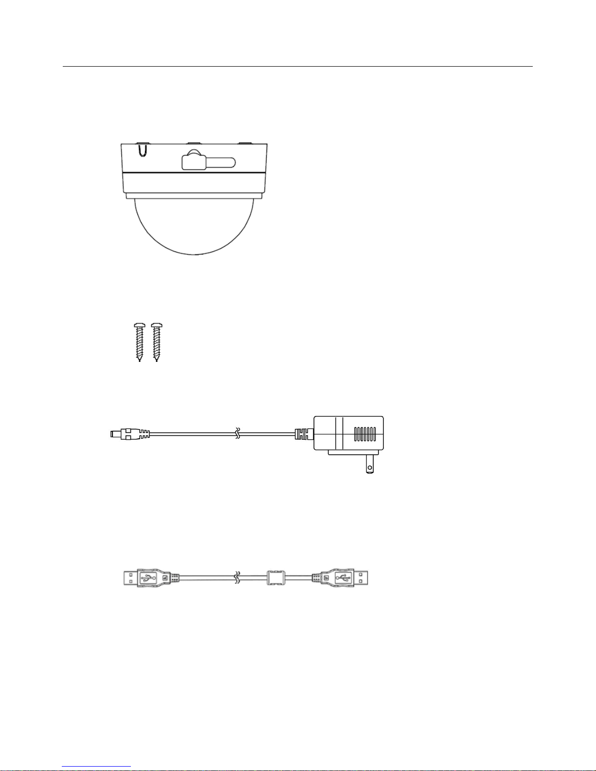
1.Contents
(1) Camera (NM33D-F) : 1 pc
(2) Camera Fixing Screw (3.5 × 20) : 2 pcs
(3) AC Adaptor (5V2A): 1 pc
Caution: Use only the AC Adaptor (5V, 2A) originally supplied with the product.
(4) USB Extension Cable (3 m) : 1 pc
Note: According to the package you purchase, other accessories may be enclosed. Please
refer to the instruction included in the package.

Page 5
2.Name of Part
Name of Part
①Dome Cover
⑧Bottom Cover Fixing Screw (3 places)
②Dome Base
⑨Screw Hole (2 places)
③USB Packing
⑩Camera Tripod Screw Mount
④USB Socket
⑪USB Socket Holder
⑤Cable Gate
⑫BNC/DC Cable
⑥Rubber Foot(3 places)
⑬BNC Connector(Male)
⑦Bottom Cover
⑭Power Connector (for AC Adaptor)
①
③
④
⑤
⑦
⑨
⑩
⑫
⑬
⑭
《view with Bottom Cover on 》
⑥
②
⑧
⑪
《view with Bottom Cover off 》

Page 6
3.Construction of Camera
①Bottom Cover
This is necessary to place the camera on the table. Remove it when installing the
camera on the wall or under the ceiling.
②Dome Base
Camera Module, BNC/DC Cable and else are mounted on this base.
③Dome Inner Cover
The protect cover for Camera Module.
④Dome Cover
The protect cover for Camera Lens.
①Bottom Cover
②Dome Base
④Dome Cover
③Dome Inner Cover
Page 7
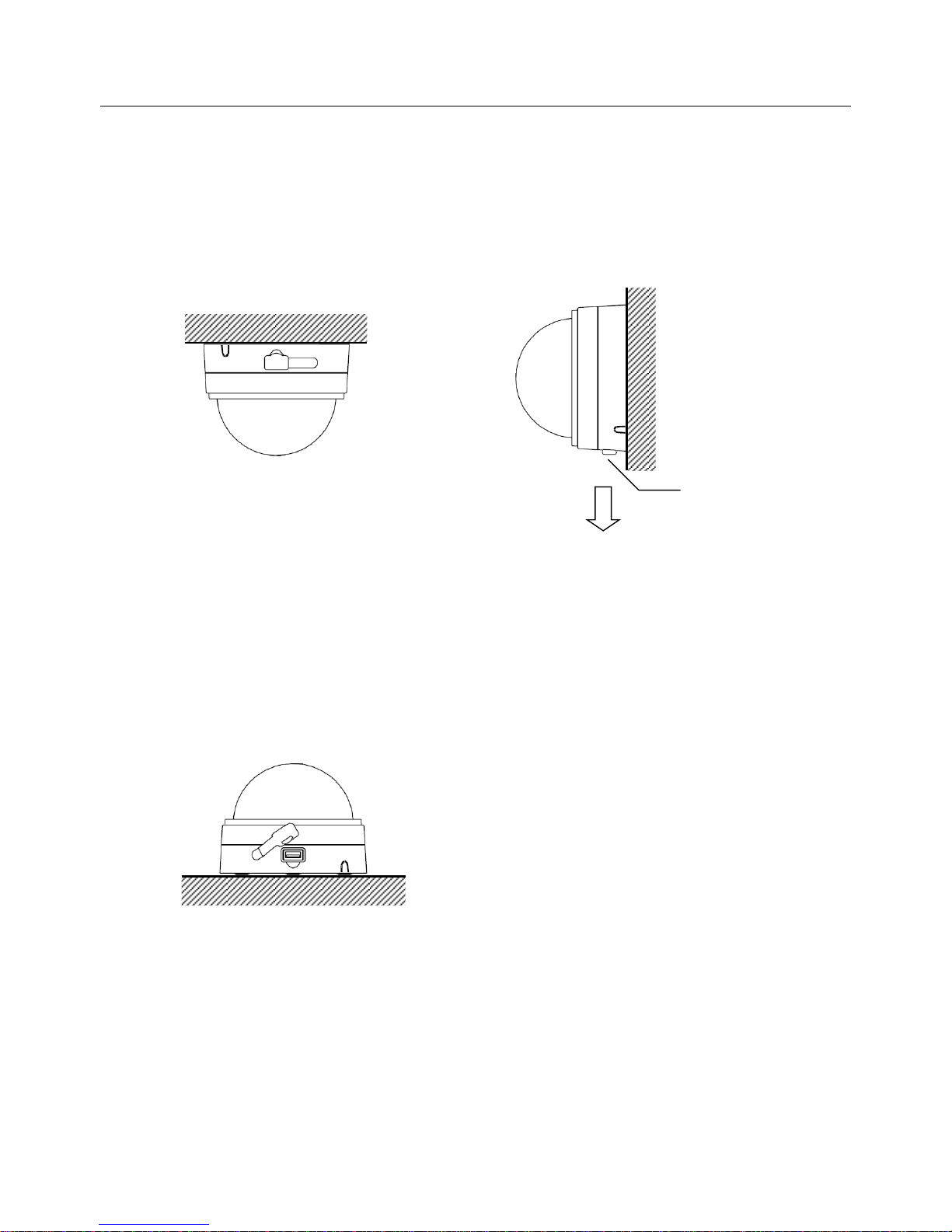
4.Advice for Installing Camera
①when Installing on the wall or under the ceiling
Remove Bottom Cover when installing the camera on the wall or under the ceiling.
Please refer to the section 6 for the installation.
For the Installation vertically, align USB Packing downward.
②when placing on the table (for the TV conference use)
When using the camera placing on the table, store BNC/DC Cable into Dome Base and
attach Bottom Cover on.
Note: For the TV conference use, a PC and the recorder software are necessary.
USB Packing
(Ceiling)
(Wall)
( on the table use )
Downward

Page 8
5.Advice for Cable Lining
In a normal case, BNC/DC Cable would like to be located behind the camera bottom with
Bottom Cover taken off.
If installing the camera on a concrete wall (no room behind the wall), it is impossible to line the
cables behind the camera. In such the case, crack the plastic piece of Cable Gate and line the
cables from the side of camera.
Note 1: The plastic piece of Cable Gate can be removed by a nipper like tool. After remove
the plastic piece, clean burrs off from Cable Gate. If burrs are left, it may cause injure
or damage of the cable.
Note 2 : The plastic piece of Cable Gate can not be replaced after once removed.
Cable Gate
BNC/DC Cable

Page 9
6.Installation (Ceiling, Wall) - Preparation
①Remove Bottom Cover
Remove Bottom Cover Screws and remove Bottom Cover from Dome Base.
②Remove Dome Cover and Dome Inner Cover
Hold Dome Cover and Dome Base firmly by hands, rotate Dome Cover counterclockwise to
remove Dome Cover from Dome Base.
Note: There is Dome Inner Cover inside of Dome Cover. Please pay attention not to drop
Dome Cover and Dome Inner Cover when removing.

Page 10
6.Installation (Ceiling, Wall) –Mark the install position
③Mark at the place to install the camera and make a through hole for lining the cables.
Make a through hole of (Φ30mm)at the center of the place to install the camera.
Place to install (Ceiling or Wall)
Through hole (φ30 mm) to
line the cables
Outer diameter of the
camera (φ122.5 mm)
Table of contents
Other OPT Corporation Security Camera manuals


