Opticstar 450CD series User manual

OPTICSTAR 450CD series
Opticstar Ltd
MANCHESTER
UNITED KINGDOM
© Opticstar Ltd 2003,2004
Any breach of Opticstar’s be vigorously prosecuted
OPTICSTAR
www.opticstar.com
Intellectual Property Rights will

Contents
Contents 2
Welcome 3
Connecting your Opticstar Camera to a Telescope 4
Connecting your Opticstar Camera to other Devices 6
Using your Opticstar Camera 7
Frame Integration Mode 9
Working in Frame Integration Mode 11
On-screen Display (OSD) 12
OSD Menu Structure 16
Technical Specification 17
Opticstar Warranty 19
© Opticstar Ltd 2003, 2004 2

Welcome to the exciting world of video astronomy. Thank you for buying this
Opticstar product and we sincerely hope that you enjoy it. Your Opticstar 450CD
serie
plan
objects.
Its colour 1/3 inch advanced CCD, sophis
doub
nois
com anding lighting conditions.
You l
Specification section.
Video astronom
popu
reco cstar deo c era will offer unequalled
views of the night sky beyond what an eyepiece can offer allowing to share these
view
Please read this manual carefully to get the most out of your Opticstar 450CD video
cam
Enjo
The
Welcome
s wide dynamic video camera will allow you to enjoy exciting views of the
s and their satellites in full colour as well as pleasing views of brighter deep skyet
ticated integrated circuitry and unusual
le frame store, not found in other frame integration or Starlight cameras, manage
e, drastically reduce smear and produce very high quality images even under
plex and dem
can find more information about your Opticstar under the Technica
y is an extension to astrophotography that has been gaining in
larity during the last few years. When connected to a TFT monitor, TV set, video
rder or personal computer your Opti vi am
s with friends away from your telescope.
y,
Opticstar team
© Opticstar Ltd 2003, 2004 3

Connecting your Opticstar Camera to a Telescope
Please handle your new Opticstar astro-video camera at all times with great care as
you would handle an expensive eyepiece. The procedure for connecting an Opticstar
camera to any telescope is near identical.
AV-TFT TV Video-In
Please follow the following steps below to attach your Opticstar camera to your
telescope.
• ensure that your telescope can accept 1.1/4” eyepieces.
• set up your telescope according to the manufacturer’s instructions.
yepiece if one is installed, you do not need an eye-piece in place.
• locate the Opticstar adaptor.
• remove your Opticstar camera with great care from its holder.
• remove the camera cap and carefully screw the Opticstar adaptor in its place.
• attach the camera to the telescope as if it was as an eyepiece and tighten up the
locking screw. Make sure the locking screw is securely tightened.
• attach the Opticstar RF cable to the camera and to your Opticstar-TFT
monitor, TV (SCART cable). video or computer via a video grabber.
• connect power leads, ensure that they are arranged in a tidy manner.
• power-on all devices.
• point you telescope to the sky and enjoy the views through your video camera.
• remove the e
Opticstar
video camera OpticstarOpticstar
power adaptor Adaptor
Video Grabber
Personal Computer
Opticstar RF cable
Modulator/SCART
Caution: Ensure that any air vents on the camera body remain
unobstructed during operation. Failure to observe this will cause
overheating that may subsequently damage your camera.
© Opticstar Ltd 2003, 2004 4

When attaching your Opticstar camera to your telescope please do not make use of a
star diagonal unless absolutely necessary. Star diagonals make the whole arrangement
less stable and bulky.
If you decide that you require a star diagonal in place please ensure that the
arrang secure. The effec rofo ort tube telescopes like
Maksutovs or Schmidt-Cassegrai
ement is t is less p
ns. und on sh
Recommended Recommended Not recommended
Connecting your Opticstar Camera to a Telescope
Caution: Do not open the casing of your Opticstar camera under any
circumstances. Opening the casing will invalidate your warranty. Opticsta
r
will not accept responsibility for any damage or injury caused by such
actions.
© Opticstar Ltd 2003, 2004 5

Introduction
lease ensure that your Opticstar camera is securely attached to your telescope as per
e instructions above. You can connect the camera via the provided RF cable to a
umber of devices including video recorders, TFT monitors with AV inputs, TV via a
CART cable or personal computer via a video grabber.
onnecting your Opticstar Camera to an AV Enabled Display
onnecting the camera to an AV TFT, TV or monitor will require no further action.
n image through your telescope should be displayed on the display once the AV
hannel has been selected.
onnecting your Opticstar Camera to a Video Recorder or TV
onnecting the camera to a video recorder will require that you tune the receiving
evice to your Opticstar camera. Please refer to the manufacturer’s instructions. Once
ned in properly, an image through your telescope should be displayed on the
isplay. Connecting your camera directly to a TV set will require a modulator.
lternatively if your TV has a SCART input a SCART cable will suffice.
onnecting your Opticstar Camera to a Personal Computer
onnecting the camera to a personal computer is normally only possible via a video
bber available from Opticstar or at your local computer store. In some cases video
r
s
r
telescope should be displayed on the computer’s display.
P
th
n
S
Connecting Your Opticstar Camera to other Devices
VCR
RF MODULATOR or SCART
Com
p
osite Video to VGA Converte
r
S-VHS or BNC
Video Grabbe
r
AV
TV
Video recorder
(
VCR
)
VGA Monito
r
PC
AV Dis
p
la
y
C
C
A
c
C
C
d
tu
d
A
C
C
gra
cards may have an RF-in that may allow you to connect the camera directly to you
omputer without the need of a video grabber. Please refer to the manufacturer’
structions to complete the installation. Once set-up properly, an image through you
c
in
© Opticstar Ltd 2003, 2004 6

Using your Opticstar Camera
Introduction
Your Opticstar video camera is a very versatile instrument and can be used in a
number of different ways, i.e.
• for observation through a telescope replacing the eye-piece/s
• for observation on a mount or tripod in conjunction with a C/CS lens
• in astrophotography for tracking purposes
Observing Through
Using you camera effectively involves a number of different steps including locating
a target, focusing and tracking the target assuming you have an equatorial mount or a
mount capable of tracking.
With the astro-camera attached and operational use the finder on your telescope to
locate your target. Set ng mode if you have this facility.
Otherwise use the manual controls to keep the target centred in the finder’s field of
view.
Now use the focuser on your telescope to bring the target into focus keeping a close
eye on the display attached to your astro-camera.
Observing With a Mounted Lens
This is more difficult to achieve as you do not have a finder to point to your target and
you will therefore need to use the arrangement as if it was a finder scope. To your
ached to your camera will offer a wide enough
a Telescope
your telescope into tracki
advantage a carefully selected lens att
field of view to assist the easy locating of night sky objects. Use your eye across the
length of the camera to roughly line up the camera with your intended target.
Such an arrangement is better suited for observing regions of the night sky, star
clusters, galaxies and to an extent the moon via the Zoom facility of your video
camera and a powerful zoom lens.
© Opticstar Ltd 2003, 2004 7

For the more serious observations and tracking of night sky objects you will greatly
ing your telescope with a digital or film camera. In this
ase the video camera needs to be attached to the main optical tube of your telescope
and o
your video camera while taking advantage of your telescope’s tracking
ttaching Lenses to the Opticstar Video Camera
a standard female C/CS screw mount
ns will perform well with your camera. As a matter of fact performance may be
eteriorated by a factor of 2 to 4 times. Opticstar provides lenses that best match your
amera’s architecture, CCD type, CCD size and functions.
general the format size of the lens must be preferably equal to or greater than the
rmat size of the camera that is used with. If the lens used is of smaller size
eripheral parts of the image will be cut-off (tunnel vision effect). For example:
o A 1/2" lens on a 1/2" format camera will produce a rectangular image with
maximum field of view (optimum).
o A 1/3" lens on a 1/3" format camera will produce a rectangular image with
maximum field of view (optimum).
o A 1/2" lens on a 1/3" format camera will produce a rectangular image with a
somewhat reduced field of view.
Tracking
Alternatively you may wish to use you astro-camera to aid tracking during long
exposure photography when us
cpr perly aligned before use.
You may also want to deploy this arrangement to take video footage of the night sky
ith
Using your Opticstar Camera
w
capabilities.
A
Your Opticstar camera comes equipped with
that supports various types of lenses. Standard and ZOOM manual Lenses can be
easily attached to your camera as can automatic lenses. When using automatic lenses
a control cable supplied with the lens will connect it to the camera.
Special care has to be taken when purchasing lenses that are best suited to your
pticstar camera. That a lens will fit it does not necessarily mean that this particularO
le
d
c
In
fo
p
o A 1/3" lens on a 1/2" format camera will produce a rather compromised
image, not recommended (worst case).
© Opticstar Ltd 2003, 2004 8

Frame Integration Mode
Introduction
ation this facility enables a 450CD series camera to
xpose a single frame for near a second at x32 frame accumulation rate. The
50C/650C models allow x128 frame accumulation and exposures of 2.5 seconds.
his enables your Opticstar 450C/450CD/650C series video camera to register
righter galaxies, star clusters and other deep sky objects in full colour.
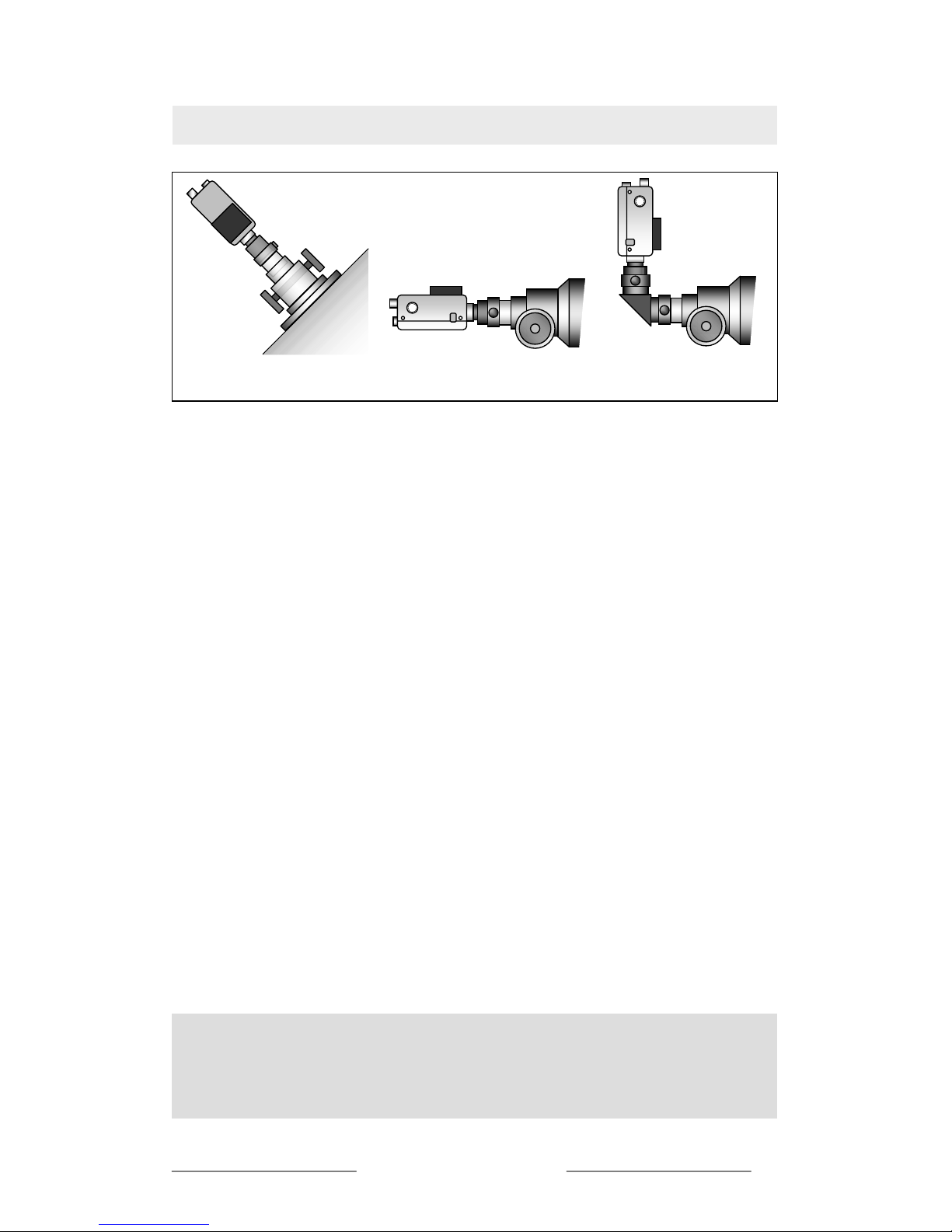
pticstar’s frame integration video cameras have been developed with astronomy in
ind and the VORTEX and ICE models benefit from built-in cooling sub-systems.
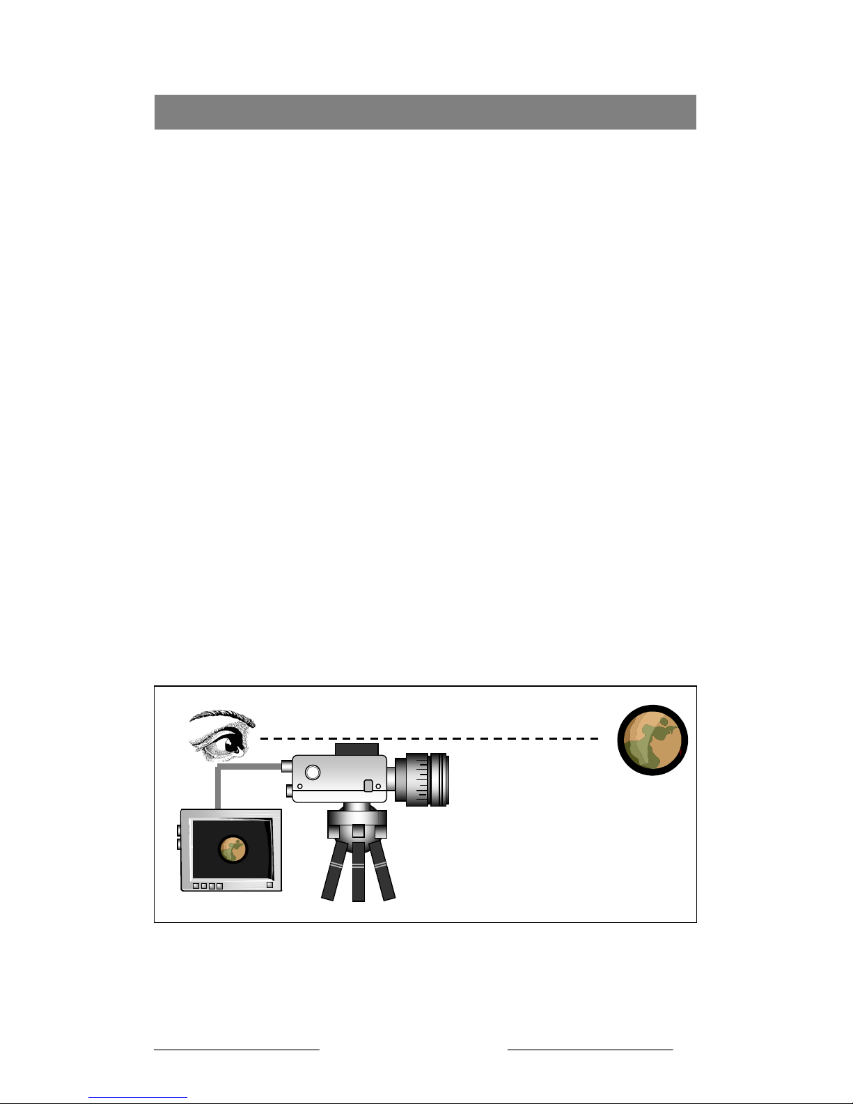
ll models feature frame integration technologies and offer an unsurpassed level of
w-light performance, enabling deep sky image formation on a suitable display.
, PAL). Thus, the minimum illumination needed by the camera to
roduce an image is decreased by a substantial factor. For example the light that is
. Opticstar frame
he Opticstar 450C/450CD/650C cameras are capable of frame integration and are
t needed.
Ho
The nu era depends on a number of
fac
camera mber of hot pixels if any at all under all
con
sky vie to high, i.e. x16, x32, x64, x128.
This is ell under high temperatures. The only
ay to keep the noise down is by ensuringhat the CCD and electronics inside the
amera are kept at sub-zero temperatures via cooled sub-systems where possible.
The 450C/450CD/650C Opticstar ranges of cameras have a frame integration mode
that allows the cameras to accumulate a variable number of frames at different shutter
speeds (beyond the standard 0.02 seconds to 0.008 seconds range). However as your
camera is capable of frame integr
e
4
T
b
O
m
A
lo
Frame integration cameras, accumulate photons on the CCD for periods from 2 up to
128 times the normal maximum exposure times found in typical video CCD cameras
(1/50 second
p
reflected by an object illuminated by a full moon is around 1 LUX
integration colour cameras are able to capture light measuring down at 0.004LUX
(Opticstar 450C series), 0.001LUX (Opticstar 650C series) and 0.015LUX (450CD
series).
T
programmable by the user through an on-screen display (OSD) menu. These user
selected and extended exposure times require that a cooling system be installed to
lower the CCD chip temperature. This reduces the dark current and the number of ‘hot
pixels’ as well as their brightness. When observing planets and their satellites hot
pixels are not an issue as long frame integration times are no
The 450CD series incorporate a double frame store and integrated circuitry that
greatly enhances image quality well beyond expectations through the camera’s
advanced Smear Cancel and White Balance technologies.
t Pixels
mber of hot pixels generated by your Opticstar cam
tors. The most important is the camera model employed. In general a Peltier cooled
(ICE) will suffer from the least nu
ditions. A non cooled camera will suffer from hot pixels especially during deep
wing when frame integration is set
due to the CCD’s inability to perform w
w
c
© Opticstar Ltd 2003, 2004 9

Frame Integration Mode
Frame Integration and Cooling
ameras are capable of eliminating noise all together
he Opticstar camera air-cooling subsystem will keep temperatures sufficiently low
pticstar 450C/450CD/650C - ICE
ra. It will take
pproximately two to three minutes for the camera to reach optimum performance.
nsure when your Opticstar camera is not in use that you switch off the
High ambient temperatures and high frame
integration rates will both contribute to unacceptable
noise levels adversely affecting the quality of the
image. This is why cooling becomes necessary as
when the temperature of the CCD is kept low so is the
noise.
Air-cooled cameras will produce good results
significantly reducing noise where Peltier cooled
c
keeping the temperature of the CCD to several
degrees below freezing.
Opticstar 450C/450CD/650C - VORTEX
T
and cool the CCD adequately to sufficiently reduce noise levels even at high frame
integration rates that are needed during deep sky viewing.
To switch on the cooling subsystem of your Opticstar camera you simply need to
power it up by rotating the knob on the side of your camera. You can use the knob to
alter the level of power to the air-cooling sub-system as required. It will take
approximately three minutes for the camera to reach optimum performance.
O
The Opticstar camera Peltier cooling subsystem will keep temperatures several
degrees below freezing and cool the CCD to reduce noise levels dramatically even at
the highest frame integration rates that are needed during deep sky viewing.
To switch on the cooling subsystem of your Opticstar camera you simply need to
power it up by pressing in the red button on the side of your came
a
The camera will not benefit from its cooling subsystem to a noticeable degree when it
is not used in frame integration mode.
Please always e
power and disconnect the camera adaptor from the power supply.
Caution: It is not uncommon that in an effort to keep the camera
temperature low some people place their cameras in a freezer sometimes
at sub zero temperatures prior to a viewing session. Note that such
practices can seriously damage your camera’s electronic and optical sub-
systems. Opticstar will not be held responsible for damage caused to a
camera under such circumstances.
© Opticstar Ltd 2003, 2004 10

tion ModeWorkin
g
in Frame Inte
g
ra
Introduction
When in frame integration mode your Opticstar camera w
images under very low lighting conditions. CCD s
1/50,1/60 ~1/2000 second shutter speed, hence the minim
LUX with a F1.2 lens at 5600k.
Your O
ill be able to capture colour
ensors in general operate on
um sensitivity is around 3
pticstar frame integration camera will drive CCD shutter speed to up to 2.5 a
econd per frame (450C/650C: 2.5 seconds, 450CD: 1 second) controllable by the
CCD will capture.
n cameras use selected Sony
CDs found in other cameras.
es cameras employ a special CCD capable of producing
xcellent quality images.
his is accessible via the push-button cursor keys and selection
he
amera will automatically increase AGC gain to return video levels back to 100
will cause the shutter speed to drop from
/60 to 1/30, 1/15, 1/8 1/4 1/2, 1, 2.5 (450C/650C) seconds.
hot pixels will also
crease, less so in the 450CD. The built-in adaptive noise cancellation circuit will
compensate but noise may still be evident even at x8 frame integration values.
Ur
Or
er
O
s
user. The longer the shutter is open, the more photons the
In addition Opticstar 450C and 650C frame integratio
EX-view CCDs that are 4 times more sensitive than C
Equally the 450CD seri
e
This in conjunction with x32 or x128 frame integration mode provide a very high
level of low light performance in general out-performing Sony Super HAD CCDs for
example by a factor of two.
In addition the 450CD series are capable of very high quality images because of a
double memory store and integrated circuitry that’s greatly reduces noise and smear,
manages well complex lighting conditions while taking advantage of the camera’s
unusually high dynamic range.
Frame Integration Mode
Frame integration mode can be switched on and set using the On-
Screen Display (OSD).
T
button on the back of your Opticstar camera.
With frame integration mode switched on as incoming light becomes weaker t
c
IRE. Once AGC reaches maximum and is no longer able to sustain 100IRE frame
integration will engage automatically. This
1
As frame integration values increase the number of undesirable
in
nder these circumstances you will need to switch on the cooling feature of you
pticstar camera that will keep the CCD at temperatures that will greatly reduce o
ven eliminate hot pixels. This can be achieved through a control on the side of you
pticstar camera. Only VORTEX and ICE models include cooling subsystems.
© Opticstar Ltd 2003, 2004 11

On-Screen Display (OSD)
Introduction
To gain access to the camera’s OSD first make
certain the camera is connected to an appropriate
display. To switch on (or OFF) the OSD press the
middle push-button at the back of your Opticstar
amera and hold until the OSD appears on the
nd the middle push-button (selection button) to
ws the user to select up to 24 characters to be displayed
t TITLE, push the right arrow to change from OFF mode
s the level of frame integration that takes place in user
x16, x24, x32. Sensor-up should be switched
cts like planets to avoid over-exposure (over-
usters. For nebulae, galaxies, comets and other faint deep sky
bjects frame integration will need to be switched to near maximum. Under these
levels of noise.
liminate noise when their cooling sub-
ystems are engaged.
gration as sensitivity is
creased the frame refresh rate will be decreased respectively.
1/100,
/120, 1/180, 1/250, 1/350, 1/500, 1/750, 1/1000, 1/1500, 1/2000, 1/3000, 1/4000,
*** MENU ***
TITLE OFF
SENSOR UP OFF
ALC/ELC ALC
INT
OPTION SET
cBACK LIGHT ON
AGC ON
W/B SELECT ATW
SYNC
screen.
Use the push-button cursors to access the menus
aZOOM ON
EXIT SAVE
make a selection.
TITLE: This function allo
continually on a video monitor. Useful when more that one camera is used as it helps
relating the displayed images to the actual cameras that generate them.
Use the cursors and highligh
to ON mode. Push the selection once more; you will see the TITLE menu. Use the
cursors and the middle push-button to type a name, once done press RTN twice to
return to the opening menu.
SENSOR UP: This determine
selected increments of x2, x4, x8, x12,
off when observing bright obje
sampling). Higher sensitivity levels are required when viewing fainter deep space
objects, including star cl
o
circumstances the resultant images will be of reduced quality showing
VORTEX and ICE models can reduce or e
s
You can increase camera sensitivity by turning frame integration mode to ON by
moving the cursor to SENSOR UP and pressing the selection button. Use the right
and left arrows to select the level of integration. At the maximum of x32 sensitivity
will go up to 0.001 LUX.. Due to the nature of frame inte
in
When set to ELC (electronic shutter speed control) the user is able to manually select
the shutter speed of the shutter in fractions of a second as follows: 1/60 (OFF),
1
1/6000, 1/8000, or 1/12000. ALC (automatic shutter control) is preferred when getting
used to the camera’s facilities as these settings are set automatically by the camera.
However more experienced users will benefit from the ability to override automatic
settings when required.
© Opticstar Ltd 2003, 2004 12

On-Screen Display (OSD)
ALC/ELC: There are two exposure control modes available on this camera. ELC
used when conditions are known where ALC mode can be used in
C rrow ct
nu. Once in the ELC m u
he arrow keys to change the LEVEL of expo
cientific and industrial purposes where lighting conditi
C mode you will be able to set the
ode to on/off or auto mode. When set to OFF the cam er
ear rejection camera”. When in AUTO mode the camera will enter in super wide
ompared to 95 ~ 110 dB of other cameras). This will allow
mode is normally
more demanding situations.
ELC Mode
While in the main Menu move the cursor to ALC/EL
ELC mode. Push the selection button to enter ELC me
can use t
, push the right a to sele
enu yo
sure. This mode is mainly for
.s ons are steady
ALC Mode
If you choose AL camera's super wide dynamic
mera will perform at as a “sup
sm
dynamic mode that will allow the on-board CPU to optimise the exposure. Finally
when set to OFF the user can take control of exposure values taking advantage of the
camera wide dynamic features.
AUTO mode
In this mode the on-board CPU will take control of all functions to produce a best shot
but the user still has control of the Auto Iris level to optimise the exposure between 70
IRE and 150 IRE as well as choose normal or dual white balance mode.
In dual white balance mode the camera will perform very well when there are marked
levels of contrast in the picture, i.e. a planet on a dark background or when lighting
temperatures from various light sources are different which is common in wide angle
astrophotography.
ON mode - super wide dynamic mode with manual interleaving
Once ON has been selected you will be able to choose the percentage weighting of
bright and dark zones to compose the best image. You can choose different IRIS
ranges to optimise the aperture, and use W W/B to select from single or dual white
alance mode.b
Dual white balance mode will use an independent white balance algorithm for bright
and dark zones, this will offer optimised colour rendering versus compromised colour
rendering as found in non dynamic cameras. You will not be able to change the
shutter speed as the on-board CPU controls this.
Off mode -super smear mode
When WDR is set to OFF the camera will turn this camera into a “super smear
rejection camera”. The 450CD series cameras are equipped with dual image memory
used in super wide dynamic processing.
Once the super wide dynamic feature is turned off the extra memory is used to enable
“super smear rejection”. Subsequently the camera is upgraded to a 154 dB smear
ejection ratio camera (cr
© Opticstar Ltd 2003, 2004 13

the camera to handle extreme contrast (i.e. when pointing to the moon) without an
auto iris lens and still provide good smear free image, vital when used through a
telescope.
Shutter speed and auto iris ranges can be set by the user to optimise the final image.
owever if the camera is equipped with a good auto iris lens the static dynamic range
r extended to 40,000,000. Such a dynamic range will allow the camera to
s can be achieved by setting any of the 48 portions of
e 8x6 LCD matrix to compensate for strong backlight that would normally
er parts of the image.
igher quality results by excluding overwhelming light
the camera to take measurements from
rker image areas.
n your camera’s cooling sub-system and enjoy your Opticstar camera
the full. Please note that only VORTEX and ICE models incorporate cooling.
ATW mode the camera will execute White Colour Balance adjustment
selected the user can fix the current White Colour
MANUAL in terms of the RED and BLUE
omponents.
Amateur astronomers are likely to find this mode more useful than super dynamic
when the camera is directly connected and sees through the telescope or when a
manual camera lens is used.
H
will be furthe
see from direct sun light to star light, and provide excellent exposure and colour
rendering.
BACK LIGHT: Backlight Compensation (BLC) can be switched to ON or OFF. BLC
allows the user to compensate for strong background lights that need to be accounted
for during viewing sessions. Thi
th
underexpose oth
By blocking certain parts of the image the camera will take
all its measurements from the non-blocked parts resulting in
h
sources.
This can also be used to deliberately overexpose parts of the
image by forcing
On-Screen Display (OSD)
da
AGC: Automatic Gain Control (AGC) (ON/OFF) or MANUAL mode. In automatic
mode your Opticstar camera adjusts gain automatically. As a rule of thumb high gain
values when in AGC in ON will produce noise. To eliminate noise under any situation
simply switch o
to
W/B SELECT: This allows the user to select between Auto Trace White Balance
(ATW), One Push Auto White Balance (AWC) and MENU mode.
In
automatically. If AWC mode is
Balance by selecting the mode and pressing the selection button. If the MENU option
is selected values can be selected from a list of two (5600oK, 3200oK) or custom
values can be set the user by selecting
c
SYNC: This mode is only applicable to cameras with VD-Lock
© Opticstar Ltd 2003, 2004 14

On-Screen Display (OSD)
OPTION: This menu leads to number of sub-menus as follows:
MASK: This function enables the user to mask (blank out) areas of the viewable
creen using four fully user programmable rectangular masks (A, B, C, D). Thus
s can be situated anywhere on the screen and can be of
ariable size. They are useful for excluding/hiding objects that otherwise would have
e current view. When set in Negative mode it may help in showing
dditional detail.
will produce a vertical reverse image of the
riginal view.
a im
XIT: This option allows the user to SAVE or via PRESET to ca c a y h n s
ticularly useful to video astronomy and can virtually eliminate
mear to near stable images, i.e. when tracking a celestial object.
s
bright objects may be totally excluded from the final image if required by individually
setting the masks to OFF/ON.
The four user definable mask
v
appeared in the picture frame.
POSI/NEGA: This function enables the user to select either a positive or negative
image of th
a
H-REV: When engaged this function will produce a horizontal reverse image of the
original view.
V-REV: When engaged this function
o
ZOOM: This function allows the user to digitally zoom into the
factor of two.
image by a m x um
En el n c a ge .
SMEAR CANCEL: Special function
This function is par
s
To enable SMEAR CANCEL follow the steps below:
1. First plug off the power
2. Push in the UP & DOWN arrow buttons at the same time and plug in the
power supply
3. Hold the two UP & DOWN arrow buttons pressed with the power on for at
least two seconds
4. Enter ALC mode, the SMEAR CANCEL function will now be available
5. Set SMEAR CANCEL function to ON
Note: Once power is switched off the smear cancellation mode will be erased, please
follow the above process to re-set.
© Opticstar Ltd 2003, 2004 15

OSD Menu Structure
4” refracto
r
© Opticstar Ltd 2003, 2004 16

Technical Specification
450CD series
© Opticstar Ltd 2003, 2004 17

© Opticstar Ltd 2003, 2004 18

OPTICSTAR WARRANTY
Dear customer,
Thank you for buying this Opticstar product, we hope that it will prove a worthwhile purchase.
In the event that your Opticstar product needs guarantee service, please contact the dealer fro
m
whom it was purchased. Alternatively contact Opticstar if the product was purchased direct. In
order to avoid any unnecessary inconvenience on your part, we suggest reading the instruction
manual carefully before contacting the dealer of our authorized service network.
Guarantee
By this consumer guarantee, Opticstar guarantees the product to be free from defects in materials
and workmanship for a period of 12 months from the time of its original purchase. If during this
period of guarantee the product proves defective due to improper materials or workmanship,
Opticstar or authorized service dealers will without charge for labour or parts, repair or (a
t
Opticstar's discretion) replace the product or its defective parts upon the terms and conditions se
t
out below.
Opticstar reserves the right (at its sole discretion) to replace spare parts of defective products o
r
to replace low cost products with either new or refurbished spare parts or products.
Conditions
1. This guarantee will be granted only when the original invoice or sales receipt (indicating the
date of purchase, product type and dealer's name) is presented together with the defective
product. Opticstar reserves the right to refuse free-of-charge guarantee service if such
a
document cannot be presented or if the information contained in it is incomplete or illegible.
2. The guarantee will not reimburse nor cover the damage resulting from adaptations o
r
adjustments which may be made to the product, without the prior written consent of Opticstar, in
order to conform to the national or local technical or safety standards in force in any countr
y
other than the ones for which the product was originally designed and manufactured.
3. This guarantee will not apply if the type or serial number on the product has been altered,
deleted, removed or maybe illegible or if the product has been disassembled.
4. This guarantee covers none of the following:
1. Periodic maintenance and repair or replacement of parts due to normal wear and tear;
Any adaptation or changes to upgrade the product from its normal purpose as describe
d
in the instruction manual, without the prior written consent of Opticstar.
2. Transport costs, home service transport cost and all risks of transport relating directl
y
or indirectly to the guarantee of the product;
3. Damage resulting from:
a. Misuse, including but not limited to (i) failure to use the product for its normal
p
urpose or in accordance with Opticstar's instructions on the proper use an
d
maintenance, and (ii) installation or use of the product in a manne
r
inconsistent with the technical or safety standards in force in the countr
y
where it is used and (iii) improper or incorrect installation of software where
applicable;
b. Repair done by non-authorized dealers or the customer himself;
c. Accidents, lightning, water, fire, improper ventilation or any cause beyond
the control of Opticstar;
d. Defects of the system into which the product is incorporated.
e. This guarantee does not affect the consumer's statutory rights under applicable
national laws in force, nor the consumer's rights against the dealer arising
from their sales/purchase product.
© Opticstar Ltd 2003, 2004 19

© Opticstar Ltd 2003, 2004 20
Table of contents