OPTOGAMA MRO User manual

!
MANUAL v3.3
MRO
MOTORISED ROTATOR
KEY for DISCOVERIES

Table of contents
Table of contents" #....................................................................................................................................2
1. Safety requirements" #...........................................................................................................................4
2. Operation principle" #.............................................................................................................................5
2.1.Features and advantages!..............................................................................................................................................5
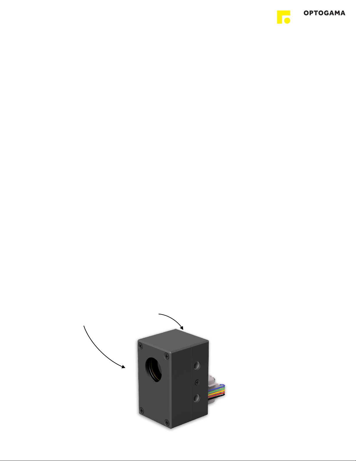
3. Product description" #............................................................................................................................6
3.1.Optical specifications!....................................................................................................................................................6
3.2.Mechanical specifications!.............................................................................................................................................6
3.3.Electronic specifications!................................................................................................................................................6
3.4.Conditions!....................................................................................................................................................................6
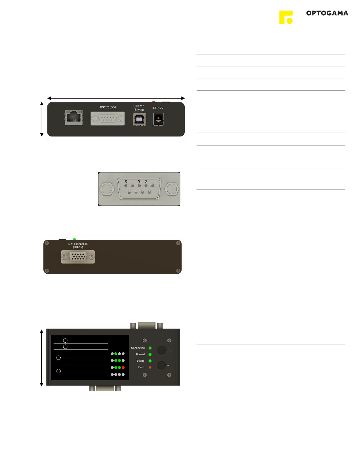
3.5.Controller!......................................................................................................................................................................7
3.5.1.Interfaces, pinout!..................................................................................................................................................7
3.5.2.LEDs, Buttons functions!.......................................................................................................................................7
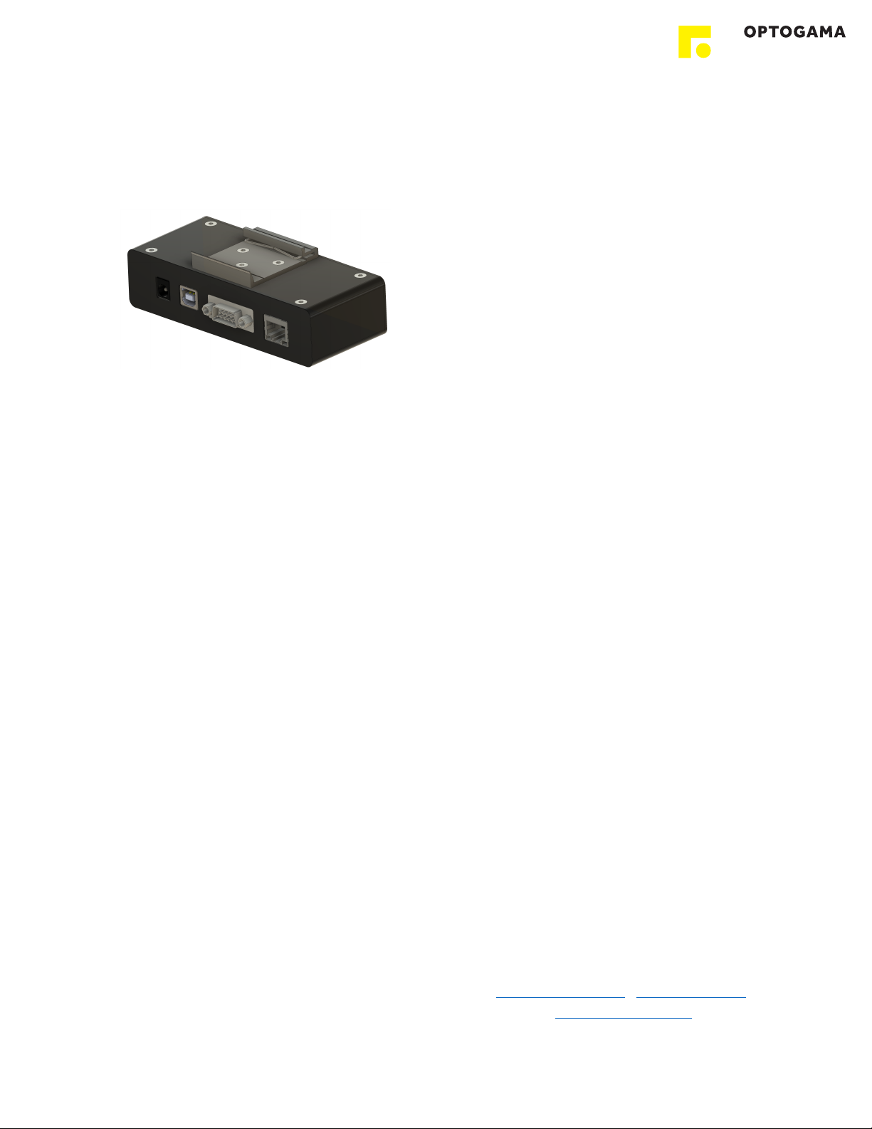
3.5.3.Mounting!..............................................................................................................................................................8
3.6.Voltage levels!................................................................................................................................................................8
3.7.What’s in the box?!........................................................................................................................................................8
4. Software" #.............................................................................................................................................8
4.1.Minimum Hardware requirements (recommended)!........................................................................................................8
4.2.System requirements!....................................................................................................................................................8
4.3.Supported client operating systems!..............................................................................................................................8
4.4.Installing the software!...................................................................................................................................................8
4.5.Using the software!......................................................................................................................................................10
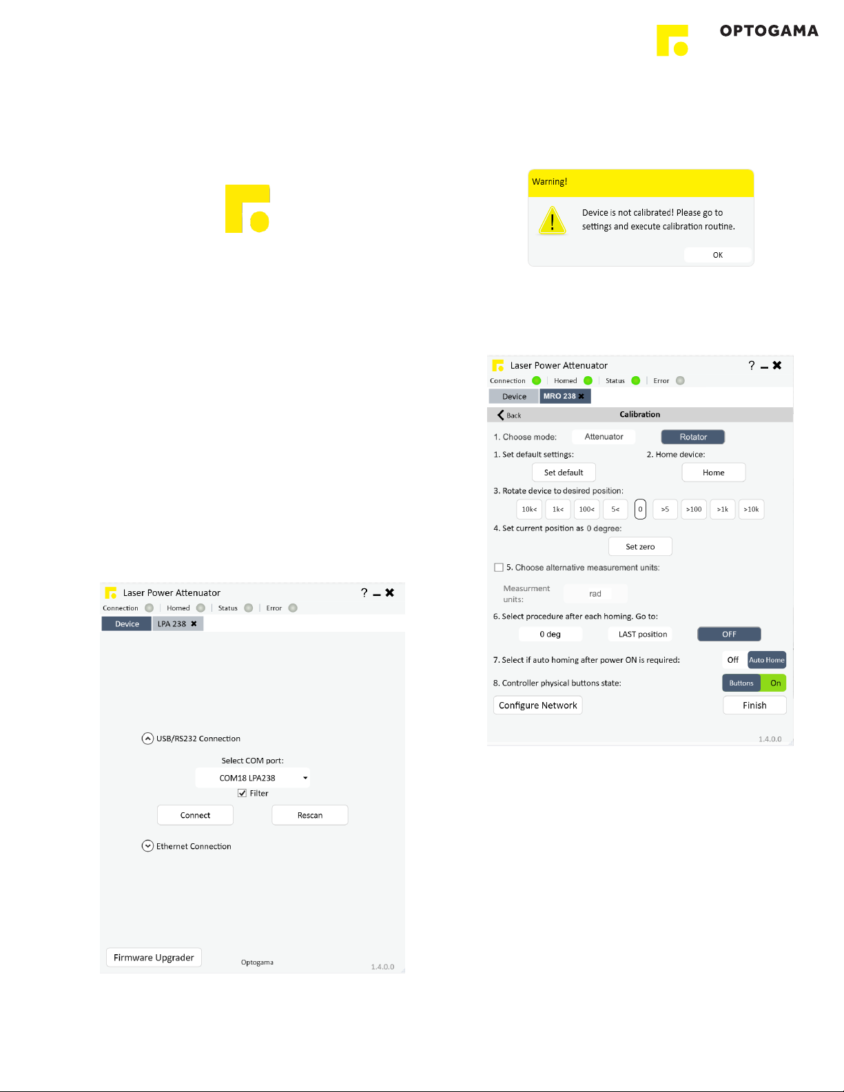
4.5.1.Connection!............................................................................................................................................................10
4.5.2.Settings, calibration!................................................................................................................................................10
4.5.3.Main window!..........................................................................................................................................................11
4.6.Ethernet connection!...................................................................................................................................................12
4.6.1.About TCP/IP pMROocol!.......................................................................................................................................12
4.6.2.Client and Server Connection!.................................................................................................................................12
4.6.3.Ethernet configuration using MRO software!...........................................................................................................13
4.6.4.Ethernet connection using MRO software!..............................................................................................................13
4.6.5.Ethernet configuration using commands!................................................................................................................14
4.7.Updating the firmware!................................................................................................................................................15
4. Commands" #......................................................................................................................................16
4.1.Interface!.....................................................................................................................................................................16
4.2.Description!.................................................................................................................................................................16
5. Troubleshooting" #................................................................................................................................19
5.1.STATUS bits explanation!.............................................................................................................................................19
5.2.Serial communication example in Python!....................................................................................................................20
6. Technical information" #.......................................................................................................................21
6.1.MRO drawings!............................................................................................................................................................21
6.2.MRO controller drawing!..............................................................................................................................................22
6.3.Power supply!..............................................................................................................................................................23
6.4.RS232 cables!.............................................................................................................................................................24
2

MRO
Motorised Rotator
Congratulations on your purchase of the motorised rotator
from Optogama, UAB.
***
October 2022
Copyright UAB Optogama. All rights reserved.
No part of this manual may be reproduced, transmitted in
any form without the permission of Optogama.
Claims will not be accepted and warranty repair will not be
carried out in case of improper use, incorrect service and
maintenance not according to product instructions.
Warranty claim shall not be accepted if there are any signs
of:
•Non-authorised alteration
•Disassembling of the device
•Mechanical or any external damage
•If warranty term has expired
•Serial number of the product is missing
Symbols#
CAUTION!
Sections marked with this symbol indicate dangerous
situations that can result in damage to the device,
components connected to it or operator.
NOTE:
Sections marked with this symbol indicate important
information on rotator or about this manual.
Due to constant development of our products we reserve
the right to make changes in the production line without
further notice. Up-to-date information is available at our
website www.optogama.com. If there are any further
questions, please contact us.
Optogama is not liable for damage or injury resulting directly
or indirectly from use of this product for anything other than
its intended purpose.
The motorised rotator is intended for industrial and scientific
use only. If there are any other electrical devices connected
to or used in conjunction with the rotator, all legal regulations
and technical standards that are applied to those devices
must be observed as well.
For any technical assistance and consultation please
3

1. Safety requirements#
•All safety instructions must be followed.
•All rules and regulations concerning the safe operation of
lasers must be known and applied while installing and
operating motorised rotator.
•Even when wearing safety glasses avoid eye contact
with direct or scattered laser light while assembling,
installing and operating the device.
•The device should never be exposed to dirt, dust or
moisture.
•Before any operation make sure the device is installed
correctly and well adjusted and all cover stickers are
removed.
•Protective measures should be considered if necessary.
•Electrical safety requirements must be complied while
operating this device.
CAUTION! High laser output power may damage or destroy
optical elements.
CAUTION! The device is meant to be used with a
collimated beam. Users take full responsibility when using
the device with a highly converging beam.
CAUTION! Before increasing laser power make sure the
device is aligned and there is no beam cut. It may damage
optical elements.
4
INPUT
COVER STICKERS MUST $
BE REMOVED BEFORE USE
OUTPUT$
!
!

2. Operation principle#
MRO is a compact motorised rotator which is based on the
LPA platform. It comes with external controller (SMC) and a
wave-plate. There are two standard options:
• ZO L/2 wave-plate (zero-order half wave-plate). This
setup is used to shift polarisation direction of linearly
polarised light.
• ZO L/4 wave-plate (zero-order quarter wave-plate). This
setup is used to convert linearly polarised light into
circularly polarised and vice versa.
NOTE: Homing is required.
CAUTION! Before increasing laser power make sure the
device is aligned and there is no beam cut. It may damage
optical elements.
2.1. Features and advantages#
• Compact design#
• High resolution - 175543 µsteps in 360 deg rotation
• High accuracy - ±10 µsteps accuracy (± 0.02 deg)
• Clear aperture - 18 mm#
• Fast adjustment - less than 0.2 sec (0 to 45 deg)
5

3. Product description#
Rotator (MRO) is a compact motorised device for laser
polarisation control.
The MRO is produced in the UV, visible and NIR spectral
ranges, from 250 nm to 2000 nm.
All optical components of the MRO are made for high LIDT
and provide stable and reliable performance even using
them with high power lasers in industrial applications.
3.1. Optical specifications#
3.2. Mechanical specifications#
3.3. Electronic specifications#
3.4. Conditions#
Clear input aperture
ø18 mm
Clear output aperture
ø18 mm
LIDT coating
>10 [J/cm2] (10 ns @ 1064 nm)
Close to open time$
0 to 45 deg
< 0.2 sec
Resolution
175,543 µsteps in full rotation
21,943 µsteps in 45deg rotation
(0.002 deg, 7.2 arcsec, 0.035
mrad)
Accuracy
±10 µsteps
(±0.02 deg)
Motor
2 phase stepper motor
200 steps with 256 µstepping
Available coatings
A. Standard wavelenghts, nm
1550
780
355
1064
400
343
1030
532
266
800
515
257
MRO - rotator
Controller
Lenght
37.5 mm
125 mm
Width
36 mm
53 mm
Height
58 mm
31 mm
Interface options:
Terminal
Using commands described
in p. 12 “Commands”
Software
Using LPA software
Input voltage
DC 12 V
Transmission speed
up to 115,200 bits/s (RS-232)
full speed USB 2.0
Operating temperature
10 0C to 40 0C
Storage temperature
-15 0C to 50 0C
6

3.5. Controller#
3.5.1. Interfaces, pinout#
1. RS-232 (DB9), USB 2.0 type B, and power plug for DC
12 V (standard plug 5.5x2.1 mm).
Fig 3. Front view of MRO controller.
2. HD-15 connector (for rotator connection to controller).
Fig 4. Back view of MRO controller.
3.5.2. LEDs, Buttons functions#
#
Fig 5. Top view of MRO controller.
31 mm
125 mm
RS232 (DB9) Pinout
2 - D+ (RS-232: Tx)
3 - D- (RS-232: Rx)
5 - GND
53 mm
Both
Tap
-
Home
Hold 2 - 6 s
-
Calibrate !
MIN power
Hold 6 - 10 s
-
Turn off buttons
Hold >10 s
-
Ignore commands
Push
-increase power (rotate CW)
LEDs !
blinking
Push
-decrease power (rotate CCW)
-
-
1
2
3
4
+
+
1#
2#
3#
4
MRO connection!
HD-15
LED explanation
Connection
Green - Power ON
Homed
Green - Device is homed and ready to use
Status
Green blinking - Device is in motion
Error
Red - there is an error, please connect PC for
further troubloushooting
BUTTONS functions
CW MROation (+)
Push “+” button to rotate clock-wise
CCW MROation (-)
Push “-“ button to rotate counter clock-
wise
Home
(Tap)
Tap both “+” & “-“ buttons to home the
device
Calibrate / Reset
(Hold 2 to 6 s)
Hold both “+” & “-“ buttons from 2 to 6
seconds to define (calibrate) current
position as 0 deg or reset it.
“Homed” and “Status” LED’s will start
blinking when it is right time to release
buttons to calibrate the device
Button lock
(Hold 6 to 10 s)
Hold both “+” & “-“ buttons longer than 6
seconds to turn off buttons. You will be able
to turn buttons ON again only via MRO
software (Settings > Buttons ON) or using
command.
“Homed”, “Status” and “Error” LED’s will
start blinking when it is right time to release
buttons to lock them.
Ignore
(Hold more than 10s)
Hold both “+” & “-“ buttons longer than 10
seconds to ignore commands.
“Homed”, “Status” and “Error” LED’s will
stop blinking when it is right time to release
buttons to ignore commands.
7

3.5.3. Mounting#
MRO uses SMC controller which is suitable for standard
*DIN35 rail mounting. You simply attach DIN35 Rail adapter
with provided screws.
*(DIN35 rail mount is optional)
3.6.Voltage levels#
The RS-232 standard defines the voltage levels that
correspond to logical one and logical zero levels for the data
transmission and the control signal lines. Valid signals are
either in the range of +3 to +15 volts or the range −3 to −15
volts with respect to the "Common Ground" (GND) pin;
consequently, the range between −3 to +3 volts is not a
valid RS-232 level. For data transmission lines (TxD, RxD),
logic one is defined as a negative voltage, the signal
condition is called "mark". Logic zero is positive and the
signal condition is termed "space".
MRO operates on signal levels of ±5#V and can accept
signal levels of up to ±15 V. Because the voltage levels are
higher than logic levels typically used by integrated circuits,
special intervening driver circuits are required to translate
logic levels. These also protect the device's internal circuitry
from short circuits or transients that may appear on the
RS-232 interface and provide sufficient current to comply
with the slew rate requirements for data transmission.
3.7.What’s in the box?#
Standard kit includes:
1. Motorised rotator (MRO)
2. Controller (SMC)
3. Software (LPA)
4. Power supply DC 12V (GST60A12-P1J)
5. USB cable (1.5 m)
NOTE: Other accessories must be purchased separately.
4. Software#
4.1. Minimum Hardware
requirements (recommended)#
4.2. System requirements#
To install the application you must have administrator rights
on your computer.
To run MRO application Microsoft .NET 4.5.2 Framework or
later must be installed. The installer detects Microsoft .NET
Framework and installs it. Administrator privileges are
required for installation. Contact your network administrator
if you do not have administrator rights on the computer.
4.3. Supported client operating
systems#
•Windows Vista SP2
•Windows 7 SP1
•Windows 8
•Windows 8.1 (.NET included with OS)
•Windows 10 (.NET 4.6 included with OS)
•Windows Server 2008 SP2/R2
•Windows Server 2012 (.NET included with OS)
4.4.Installing the software#
1. Check and download the latest LPA software from the
flash drive which was sent with the device itself, website
(www.optogama.com, www.4lasers.com) or contact us
2. Run the downloaded software installation file. Installation
window will appear, click “Next” to continue:
Top
Bottom
Processor
1 Ghz
RAM
512 Mb
Disk space
32-bit
4,5 Gb
64-bit
4,5 Gb
8

3. Select “Create a desktop shortcut” if it is necessary and
click “Next”:
Review setup information and proceed the installation. To
continue click “Install”:
4. Setup will finish the installation:
5. Press “Finish” to end the installation:
Connect the device and controller via HD-15 cable.
6. Connect the PC and controller via USB or RS232 cable.
7. Plug in power supply to controller and AC adaptor to wall
outlet.
8. The device will be detected and configured.
9. The device installation is complete.
9

4.5. Using the software#
CAUTION! Do not switch the laser ON if the device is not
adjusted properly, it may damage or destroy optical
elements.
Launch LPA program using LPA icon on the desktop.
4.5.1. Connection#
10. Device selector window will appear. Select COM port (to
which the rotator is connected) from the drop down
menu. Press “Connect” to connect the device or
“Rescan” if your device is not visible.
Select “Filter” when device is connected via USB cable.
All other COM ports will be hidden except our device.
NOTE: When connecting via RS232 cable “Filter” must
be deselected, otherwise device will not be visible.
NOTE: Rotator will be seen as MROxxx (for ex. MRO001)
4.5.2. Settings, calibration#
11. Using rotator for the first time the calibration is required.
The information window will appear:
12. For MRO calibration, move your mouse to the left side
of the window on a gear symbol from the sliding menu
and select “Settings”. Settings menu will appear:
13. To succeed calibration please follow calibration steps:
1.Choose device’s mode (rotator by default)
NOTE: Polariser is necessary for attenuator mode.
2. Set default settings
3. Home device
4. Find required position by rotating the waveplate (it
will be defined as 0 degree)
5. Set current position as 0 deg.
6. Choose alternative measurement units if
necessary (radians are by default)
7. Select procedure after each homing:
LPA
10

1. 0 deg - each time after homing the device,
the attenuator instantly will go to defined
position (0 degree).
2. Last position - each time after homing the
device, the attenuator will go to last position
before .
3. OFF - each time after homing the device,
the attenuator will remain in home position.
8. Select if automatic homing is required after
turning the device ON.
9. Choose if physical buttons are required, if no, you
can lock them by choosing “Buttons OFF”.
10.After finishing the calibration routine you will be
greeted into MAIN window
NOTE: After homing the device message box will appear
4.5.3. Main window#
The calibration procedure is done successfully if there is no error, device is connected and homed. The device is ready to use.
11
Preset buttons#
Click “Edit” to add or edit
preset t values for a quick
change
Settings#
Select this icon to open
calibration and settings
window
Angle value in deg#
Enter required power value.
Press “Enter”.
Power Slider#
Move the slider to change
angle
Buttons for incremental
change#
Click grey button to rotate
clockwise or counter-
clockwise.
Save as preset#
Save current angle as preset
button in required slot.
Angle value in radians#
Click double arrows to switch
units (to operate in radians).
Homed$
Green - device is
homed
Connection$
Green - device is
connected
Status$
Green - if blinking device is in
motion
Error$
Red - indicates and error. Drag
cursor here to obtain error
Reconnect#
Select this icon to reconnect
the device if it is disconnected
Sliding Menu#
Drag cursor here to expand
menu
Command line#
Select this icon to open
command terminal window
Device selector tab
Connected device tab
About$
Click to open About window
for manual

4.6. Ethernet connection#
MRO software has implemented TCP/IP communication. It
is practically plug-and-play usage in the software once
network settings of the MRO device are correctly configured
for TCP/IP communication. The interface and usage of the
software stay the same as for USB or RS-232, only
communication pMROocol is changed.
NOTE: MRO network settings must be configured using
USB or RS-232 connection before use. This can be done
using commands from Command description (p. 16) or
using software.
4.6.1. About TCP/IP pMROocol#
The device can communicate via RJ45 connector using
“Transmission Control PMROocol/Internet PMROocol”
(TCP/IP) network pMROocol. The TCP/IP pMROocol is
designed such that each computer or device in a network
has the unique IP address and each IP address can open
and communicate over up to 65535 different “ports” for
sending and receiving data to or from any other network
device. The IP address uniquely identifies the computer or
device on the network and a “Port Number” identifies a
specific connection between one computer or device and
another (between two IP addresses). A TCP/IP Port can be
thought of as a private two-way communications line where
the port number is used to identify a unique connection
between two devices. The TCP/IP pMROocol creates a
“virtual IP port” and the network hardware and software are
responsible for routing data in and out of each virtual IP
port.
4.6.2. Client and Server
Connection#
TCP/IP connection works in a manner like a telephone call
where someone has to initiate the connection by dialling the
phone. At the other end of the connection, someone has to
be listening for calls and then pick up the line when a call
comes in. The Client in a TCP/IP connection is the
MRO controller that “dials the phone” and the “Server” is
the computer or another device that is “listening” for
calls to come in. The Client needs to know the IP address of
whatever Server it wants to connect to and it also needs to
know the port number that it wants to send and receive
data through after a connection has been established. The
server only has to listen for connections and either accept
them or reject when they are initiated by a client.
Once a connection through a TCP/IP port has been
established between a TCP/IP Client and a TCP/IP Server,
data can be sent in either direction. The MRO controller will
never send any data through TCP/IP port unless asked by
the TCP/IP Server sending commands (see in command
description Pg. 16). The connection between a Client and a
Server remains open until either the client or the server
terminates the connection.
The above description is basic and describes a general
concept of how TCP/IP communication works. For deeper
understanding at least networking basics must be known.
12

4.6.3. Ethernet configuration
using MRO software
1. Connect MRO to PC via USB or RS232.
2. Open MRO software. After connecting the MRO go to
“Settings” > “Configure Network”. The LAN Settings
window will pop-up:
On the left side of the Network Settings window, current
network settings for MRO will be displayed.
On the right side of the window network interfaces which
are available will be listed, usually, there’s only one available
interface. Furthermore, IP addresses will be suggested for
MRO network settings from the available interface.
3. Configure Ethernet settings for MRO:
3.1. Input Network (TCP) Server (your PC) IP address. (It
is filled automatically if only one network interface is
available)
3.2. Input Network client (MRO) IP address. Choose any,
but It has to be unique IP address in your local
network.
3.3. Input Router/Default Gateway address. (It is filled
automatically if only one network interface is available)
3.4. Input Subnet Mask address. (It is filled automatically
if only one network interface is available)
3.5. Input Network Port. By default it is 555, but you can
choose any up to 65535.
NOTE: Default “Network port”: 555.
Configuration is complete.
4.6.4. Ethernet connection using
MRO software#
1. Connect MRO controller via Ethernet cable (RJ45 plug).
2. Open MRO software.
3. Open “Ethernet Connection” and select your Network
(TCP) Server IP from the drop-down menu (usually it is
only one available address)
4. Input communication port (555 by default) and press
“Start Server”.
NOTE: Port must be the same for both Network (TCP)
server and Network client (MRO).
5. If everything is configured correctly your MRO
device should appear in the connected devices list.
You will see MRO serial number and IP from which it
connected (if local network, IP should be the same as
configured). Select device you want to use and press
“Open”.
For further usage refer to section “4.5 Using the
Software”.
After the TCP server is started it constantly waits only for
MRO devices.
NOTE: If any other device or computer tries to connect to
the TCP Server, connection is refused.
13

4.6.5. Ethernet configuration
using commands#
In this manual two cases of network settings configurations
will be reviewed:
• First case is when MRO and device communicate on the
same network.
• Second case when MRO and other device communicate
from different networks over internet. The latter is like the
first case but has more steps included.
1. MRO and other device communication on the same
network:
As shown in the picture device that wants to communicate
with MRO has to be TCP Server, while MRO is TCP Client
by default. Both Server and MRO are connected to the
router. The server may be connected via Ethernet cable or
Wi-Fi. According to this setup MRO network settings have
to be set as follows:
• “MRO>NIP!_192.168.30.140” – Client (MRO) IP address
in the local network.
• “MRO>NSIP!_192.168.30.153” – Server IP address in
the local network.
• “MRO>GWIP!_192.168.30.100” – Router/Default
Gateway IP address.
• “MRO>NMSK!_255.255.255.0” – Local network subnet
mask.
• “MRO>NPRT!_555” – Port over which both devices
communicate.
With these settings, MRO device which has Network client
IP address 192.168.30.140, will try to connect to Network
Server (PC) with IP address 192.168.30.153 over Port 555.
The connection will be made through Router whose IP
address is 192.168.30.100 and both devices are connected
to it. If everything is configured correctly TCP Server during
“listening” of Port 555 should get a request of connection
from MRO device.
2. MRO and other device communication from different
networks over internet:
MRO is a Client and another device is a Server. In this
case ,both devices are on different networks and the only
way they can reach each other is through the internet. To do
this MRO settings have to be as following:
• “MRO>NIP!_192.168.0.3” – Client (MRO) IP address in
the local network.
• “MRO>NSIP!_5.149.19.200” – Server’s Public IP
Address.
• “MRO>GWIP!_192.168.0.1” – Default Gateway/Router1
IP address.
• “MRO>NMSK!_255.255.255.0” – Local network subnet
mask.
• “MRO>NPRT!_22000” – Port over which both devices
communicate.
In this case, MRO will try to connect to a server with port
22000 over the internet which has the Public IP Address
5.149.19.200. Router 2 should accept connection from
MRO and Port Forward to a device in the Local Network
with IP address 192.168.0.111.
Router
Network (TCP)
Server
Network Client$
(MRO)
IP: 192.168.30.140
Connecting to 192.168.30.153:555
IP: 192.168.30.153
Listening on port 555
Segmented
192.168.30.xxx
Router 1
Network (TCP) Server
Network Client (MRO)
Connecting to:
5.149.19.200
Port: 22000
TCP Server: 192.168.0.111
Router 2
Internet
Forwarding to:
192.168.0.111
Port: 22000
Visible as:
5.149.19.200
14

NOTE: Port Forwarding must be configured on Router 2.
This procedure varies on different devices and instructions
should be available on Router 2 user manual.
4.7. Updating the firmware#
If your device firmware version doesn’t match to software’s
firmware version while connecting to device via LPA
software you’ll be asked to update your device. If update
request pops-up, but you want to keep current firmware
and use LPA software, you must use software compatible
with that firmware version.
NOTE: Compatible software had been delivered with
In order to update your device or rewrite device firmware -
USB cable must be used (update through RS232 cable is
not available).
1. Click button “Firmware Upgrader” in the About tab of
MRO software:
2. In the opened window press “Update” button. You will
be asked if you really want to update device:
After a warning device motors will be shut down and
update will start:
3. Update should be done in about a minute. If everything
went successfully message box like this should pop-up:
Now you’re ready to go.
15

4. Commands#4.1. Interface!
The device can be controlled using either USB 2.0 or
RS-232 interface. The device will switch to the required
interface upon connection of the appropriate cable.
When using the RS-232 interface, the controller
communicates on the configured baud rate (see
Command descriptions), using 8 data bits, no parity and
1 stop bit.
When the device is connected to the PC through the USB
interface, it will appear as a Virtual Serial COM port, so
all PC side communications are interchangeable between
the two interfaces.
All communications with the device are conducted by
sending literal ASCII string commands terminated with
the newline character \n. For example, the power can
be set to 10% by issuing a “MRO>PWR!_10\n” command
to which the device will respond with “MRO>PWR_10\n”.
4.2. Description#
Command
Response
Comments
Example usage
User command
Device response
Motion | Power - PWR, Angle - ANG, Target - TGT, Stop - STP
MRO>PWR?
MRO>PWR_X.XXX
When used in attenuator mode.
Command used to get the current
power value in percentages.
MRO>PWR?
MRO>PWR!_45.125
MRO>PWR!_X.XXX
MRO>PWR!_X.XXX
When used in attenuator mode.
Command used to set a new power
value in percentages.
MRO>PWR!_10
MRO>PWR_10.000
MRO>PWR!_45.1
MRO>PWR_45.100
MRO>PWR!_0.07
MRO>PWR_0.070
MRO>ANG?
MRO>ANG_X.XXX
Command used to get the current
angle value in degrees.
MRO>ANG?
MRO>ANG_22.143
MRO>ANG!_X.XXX
MRO>ANG_X.XXX
Command used to set the angle value
in degrees.
MRO>ANG!_22.5
MRO>ANG_22.500
MRO>TGT!_X.XXX
MRO>TGT_X.XXX
Command used to set the target in
micro-steps.
MRO>TGT!_44521
MRO>TGT_44521
MRO>TGT?
MRO>TGT_X.XXX
Command used to get the current
position in micro-steps.
MRO>TGT?
MRO>TGT_44521
MRO>STP!
MRO>STP
Command used to stop motor instantly.
Device could be used normally, homing
is not require.
MRO>STP!
MRO>STP
Homing, Calibration & Auto-go | Homing - HOME, Auto-homing - AHOME, Calibration - DEF, Auto-go - AUTOGO
MRO>HOME!
MRO>HOME
Command used to home the device
(motor goes to home position - TGT_0).
MRO>HOME!
MRO>HOME
MRO>AHOME!
MRO>AHOME_1
Command used to turn ON auto homing after power ON.
MRO>NOAHOME!
MRO>AHOME_0
Command used to turn OFF auto homing after power ON.
MRO>AHOME?
MRO>AHOME_0
Command used to get auto homing state. If 1 - Auto homing is enabled, 0 - disabled.
16

MRO>DEF!
MRO>DEF_offset
Command used to define current
position as 0 deg. Used for calibration.
MRO>DEF!
MRO>DEF_-25432
MRO>DEF?
MRO>DEF_offset
Command used to get an offset value
from home to 0 deg position. Used for
calibration.
MRO>DEF?
MRO>DEF_-25432
MRO>AUTOGO!_X
MRO>AHOME_X
Command used to set procedure after each homing:
0 - device remains in home position (TGT_0);
1 - device goes to 0 deg position (calibrated position as 0 deg);
2 - device goes to LAST position it was before homing.
MRO>AUTOGO?
MRO>AHOME_X
Command used to get which procedure after each homing is selected:
0 - device remains in home position (TGT_0);
1 - device goes to 0 deg position (calibrated position as 0 deg);
2 - device goes to LAST position it was before homing.
Settings | Baud rate - BAUD, Buttons lock - KEYLOCK, Default settings - LDF
MRO>BAUD?
MRO>BAUD_baud rate
Command used to get baud rate.
MRO>BAUD?
MRO>BAUD_115200
MRO>BAUD!_baud rate
MRO>BAUD_baud rate
Command used to set baud rate.
Available speeds:
115200, 57600, 38400,
19200, 9600, 4800.
Other values are ignored.
MRO>BAUD!_57600
MRO>BAUD_57600
MRO>KEYLOCK!
MRO>KEYLOCK_X
Command used to ENABLE / DISABLE controller physical buttons:
1 - disabled, 0 - enabled.
MRO>KEYLOCK?
MRO>KEYLOCK_X
Command used to get controller physical buttons state:
1 - disabled, 0 - enabled.
MRO>LDF!
MRO>LDF
Command used to load default settings. Device after this command must be:
1. Homed;
2. Recalibrated.
Ethernet settings
MRO>NIP!_x.x.x.x
MRO>NIP_x.x.x.x
Command used to set Client (MRO) IP
address in local network.
MRO>NIP!_192.168.30.140
MRO>NIP_192.168.30.140
MRO>NIP?
MRO>NIP_x.x.x.x
Command used to get Client (MRO) IP
address in local network.
MRO>NIP?
MRO>NIP_192.168.30.140
MRO>NSIP!_x.x.x.x
MRO>NSIP_x.x.x.x
Command used to set Server (PC) IP
address in local or public network.
MRO>NSIP!
_192.168.30.153
MRO>NSIP_192.168.30.15
3
MRO>NSIP?
MRO>NSIP_x.x.x.x
Command used to get Server (PC) IP
address in local or public network.
MRO>NSIP?
MRO>NSIP_192.168.30.15
3
MRO>GWIP!_x.x.x.x
MRO>GWIP_x.x.x.x
Command used to set Default Gateway
IP address.
MRO>GWIP!
_192.168.30.100
MRO>GWIP_192.168.30.10
0
MRO>GWIP?
MRO>GWIP_x.x.x.x
Command used to get Default
Gateway IP address.
MRO>GWIP?
MRO>GWIP_192.168.30.10
0
MRO>NMSK!_x.x.x.x
MRO>NMSK_x.x.x.x
Command used to set Local network
subnet mask.
MRO>NMSK!
_255.255.255.0
MRO>NMSK_255.255.255.
0
MRO>NMSK?
MRO>NMSK_x.x.x.x
Command used to get Local network
subnet mask.
MRO>NMSK?
MRO>NMSK_255.255.255.
0
MRO>NPRT!_x
MRO>NPRT_x
Command used to set Port over which
both devices communicate
(555 by default)
MRO>NPRT!_555
MRO>NPRT_555
Command
Response
Comments
Example usage
User command
Device response
17

MRO>NPRT?
MRO>NPRT_x
Command used to get Port over which
both devices communicate
(555 by default)
MRO>NPRT?
MRO>NPRT_555
Information | Device state - STATUS, Wavelength - WL, Firmware v. - FW, Serial number - ID
MRO>STATUS?
MRO>X_Y
Command used to get the current state
of the device. X signifies if motor is ON.
Y signifies the error byte.
X=”1” motor is ON (enabled)
X=”0” motor is OFF (disabled)
Y = 16 bits digit with following bits:
bit0 -> driver error
bit1 -> driver high temperature warning
bit2 -> driver over temperature
bit3 -> some type of error in the driver
load
bit4 -> load warning – open load on
phase A or B
bit5 -> under voltage error
bit6 -> external memory error, working/
calibration data may be corrupted
bit7 -> reset has occurred
bit8 -> left limit switch is pressed
bit9 -> right limit switch is pressed
bit10 -> stall guard flag is active
bit11 -> motor is stand still
bit12 -> motor target velocity reached
bit13 -> target position reached
bit14 -> homing procedure was run
after the reset
bit15 -> device calibration is done
More info on pg. 19
MRO>STATUS?
MRO>1_0
MRO>STATUS?
MRO>0_0
MRO>STATUS?
MRO>1_2
MRO>WL?
MRO>WL_XXX
Command used to get the design
wavelength.
MRO>WL?
MRO>WL_355
MRO>FW?
MRO>_Firmware version
Command used to get firmware
version.
MRO>FW?
MRO>_1.0.0.1
MRO>ID?
MRO>_MROXXXXXXX
Command used to get serial number.
MRO>ID?
MRO>_MRO1901001
Other | Echo, Reset, Motor ON/OFF
MRO>ECHO!
MRO>ECHO
Command used for troubleshooting.
The device echoes sent command
before sending the response.
MRO>ECHO!
MRO>TGT?
MRO>ECHO
MRO>TGT?
MRO>TGT_45602
MRO>NOECHO!
MRO>NOECHO
Command used to disable ECHO command.
MRO>RESET!
MRO>RESET
Command used to reinitialise device.
MRO>RESET!
MRO>RESET
MRO>OFF!
MRO>OFF
Command used to turn motor OFF.
MRO>OFF!
MRO>OFF
MRO>ON!
MRO>ON
Command used to turn motor ON.
MRO>ON!
MRO>ON
Command
Response
Comments
Example usage
User command
Device response
18

5. Troubleshooting#
5.1. STATUS bits explanation#
Bit0 – driver error. This bit is high when some error in motor
driver happens.
Bit1 – driver high temperature warning. Bit is high when
motor driver is in pre-warning temperature range which
exceeds 120°C.
Bit2 -#driver over temperature. Bit is high when motor driver
reaches 150°C. After triggering this temperature the driver
remains switched off until the system temperature falls
below 120°C. The thermal shutdown is just an emergency
measure and temperature rising is prevented by the design.
Bit3 – dome type of error in the driver load. Motor driver
power stages are pMROected against a short circuit
condition. Once a short condition is safely detected the
corresponding driver bridge becomes switched off, and flag
becomes set.
Bit4 - load warning – open load on phase A or B of stepper
motor driver. However, the flag have just informative
character and do not cause any action of the driver. This
flag works only at low motor velocity operation, which is not
the case.
Bit5 – under voltage error. Indicates an under voltage on the
motor driver charge pump. The driver is disabled in this
case.
Bit6 – external memory error working/calibration data may
be corrupted. Flag is set if there was an error reading data
from EEPROM.
Bit7 – reset has occurred. Indicates that the motor driver
has been reset since the last read access to STATUS All
registers have been cleared to reset values.
Bit8/Bit9 – left/right limit switch is pressed. Limit switches
are used as reference point in homing procedure.
Bit10 – StallGuard is active. Signal that motor stall is
detected. StallGuard provides sensor-less stall detection
and mechanical load measurement.
Bit11 – motor is stand still. This flag indicates motor stand
still in each operation mode.
Bit12 – motor target velocity reached. Signals, that the
target velocity is reached. This flag becomes set while
actual and maximum speed match.
Bit13 – target position reached. Signals, that the target
position is reached. This flag becomes set while actual and
target position match.
Bit14 – Homing procedure was run after the reset.
Indicates, that after power on stepper motor was homed
and is ready for precise position control.
Bit15 – Device calibration is done. Indicates, that
“MRO>DEF!” command was send and minimum laser
power position is known.
19

5.2. Serial communication example in Python#
!
20
Table of contents
Other OPTOGAMA Adapter manuals
Popular Adapter manuals by other brands

Broadcom
Broadcom BCM92045NMD quick start guide

Hama
Hama 34121998 operating instructions

Magnadyne
Magnadyne WC-USB-B installation instructions

Patton electronics
Patton electronics 3004 user manual

Mellanox Technologies
Mellanox Technologies ConnectX-4 Lx user manual

Aiphone
Aiphone RY-IP44 Programming manual