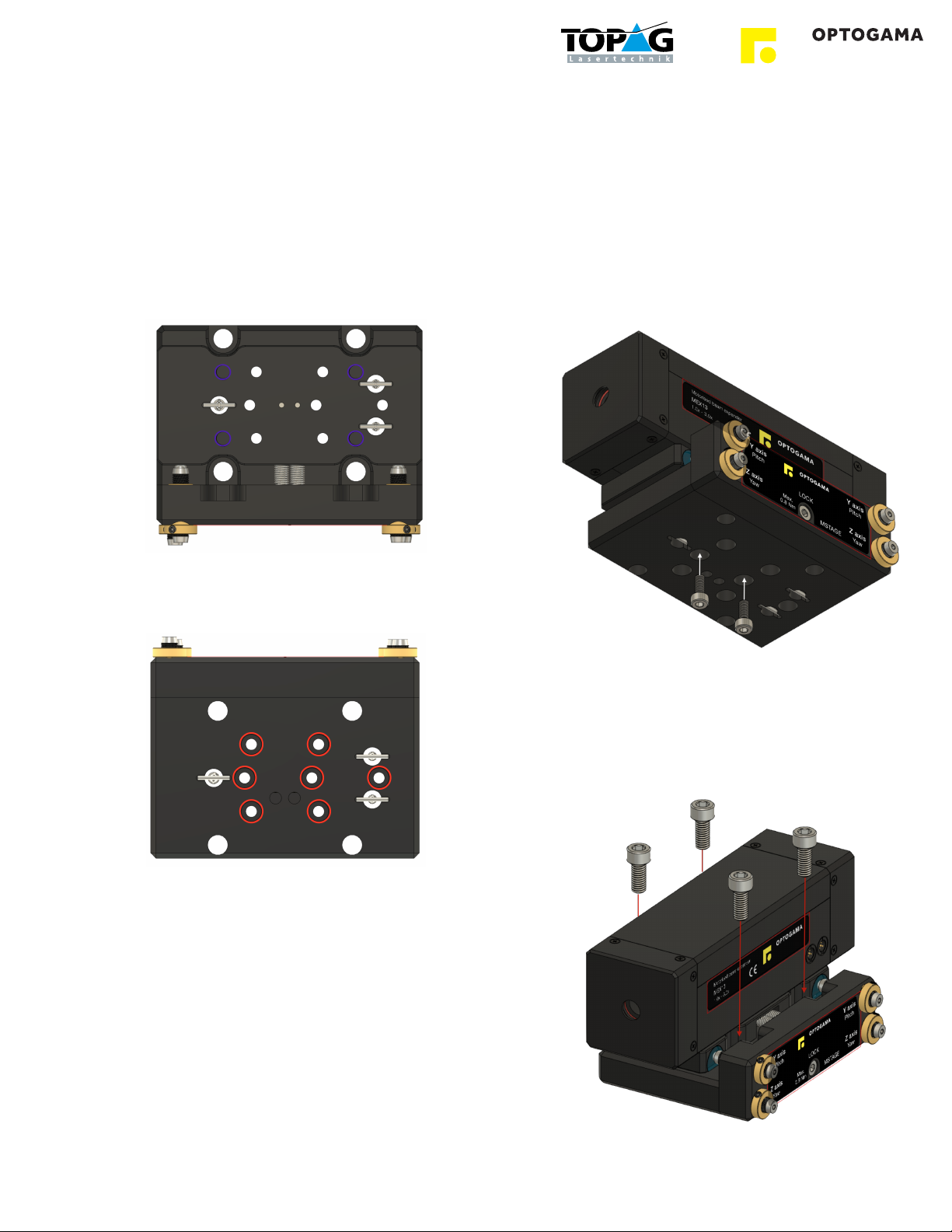
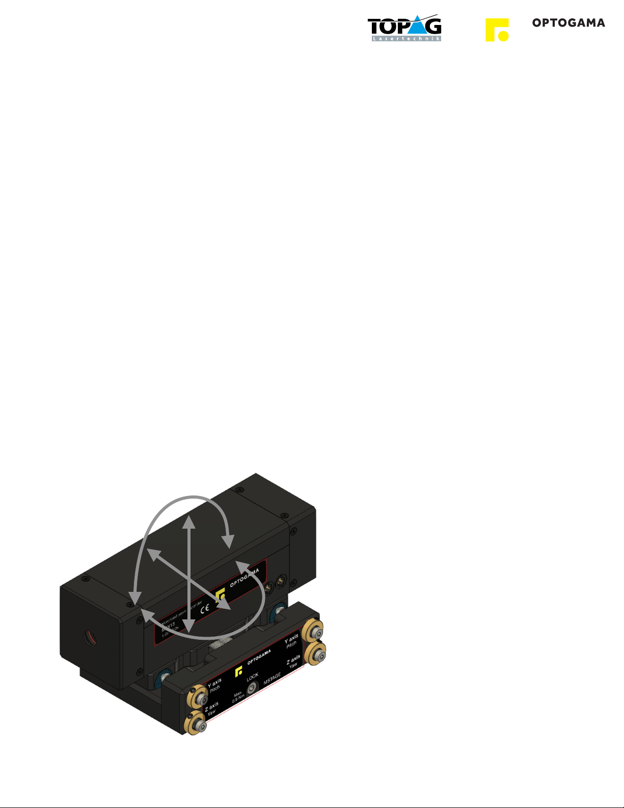
OPTOGAMA MSTAGE Series User manual

!
MANUAL v1.1
MSTAGE
MANUAL 4 AXIS
TRANSLATION STAGE
MSTAGE series
KEY for DISCOVERIES
Z
Y
Pitch
Yaw

Table of contents"
Table of contents#2"....................................................................................................................................
1. Safety requirements#4"...........................................................................................................................
2. Features and advantages#5"..................................................................................................................
3. What’s in the box?!5...............................................................................................................................................................
4. Product description#5"............................................................................................................................
4.1.Mechanical specifications!5.............................................................................................................................................
5. Mounting!6.............................................................................................................................................................................
5.1.Mounting holes!6.............................................................................................................................................................
5.2.Mounting MEX motorised beam expander!6....................................................................................................................
6. Positioning the stage!7............................................................................................................................................................
7. Technical drawings#8.............................................................................................................................
2

MSTAGE
MANUAL 4-axis
TRANSLATION STAGE
Congratulations on your purchase of the manual translation
stage from Optogama, UAB.
***
December 2019
Copyright UAB Optogama. All rights reserved.
No part of this manual may be reproduced, transmitted in
any form without the permission of Optogama.
Claims will not be accepted and warranty repair will not be
carried out in case of improper use, incorrect service and
maintenance not according to product instructions.
Warranty claim shall not be accepted if there are any signs
of:
•Non-authorised alteration
•Disassembling of the device
•Mechanical or any external damage
•If warranty term has expired
•Serial number of the product is missing
Symbols"
CAUTION!
Sections marked with this symbol indicate dangerous
situations that can result in damage to the device,
components connected to it or operator.
NOTE:
Sections marked with this symbol indicate important
information on manual translation stage or about this
manual.
Due to constant development of our products we reserve
the right to make changes in the production line without
further notice. Up-to-date information is available at our
website www.optogama.com. If there are any further
questions, please contact us.
Optogama is not liable for damage or injury resulting directly
or indirectly from use of this product for anything other than
its intended purpose.
For any technical assistance and consultation please
3

1. Safety requirements"
•All safety instructions must be followed.
•All rules and regulations concerning the safe operation of
lasers must be known and applied while installing and
operating manual translation stage.
•Even when wearing safety glasses avoid eye contact
with direct or scattered laser light while assembling,
installing and operating the device.
•The device should never be exposed to dirt, dust or
moisture.
•While locking the stage with locking screw “LOCK” less
than 0.8 Nm force must be applied, otherwise the
locking mechanism may be harmed. (It is not
recommended to use Allen key)
CAUTION! Do not use more than 0.8 Nm force while
locking the stage with “LOCK” screw.
CAUTION! Do not adjust the platform with adjustment
microscrews while the platform or microscrews are locked. It
may damage the locking mechanism, or any other part of
the translation stage.
4
> 1 Nm
(Too much torque possible)

2. Features and advantages"
• Sapphire contact pads
• Platform’s locking mechanism
• Industrial design
• 4 axis fine adjustment
• Maximum load up to 1.5 kg
• Can be fixed on both Metric and Imperial
optical breadboards and tables
3. What’s in the box?"
Standard kit includes:
1. Manual translation stage
2. 3 x M4x0.7 10mm long screws for MEX mounting
NOTE: Other accessories must be purchased separately.
4. Product description"
MSTAGE is an industrial 4-axis manual translation stage with
locking mechanism. It has sapphire contact pads for
prolonged accurate adjustment.
There are four M6x0.25 microscrews for adjusting platform’s
pitch, yaw, Y and Z axis. Two microscrews control platform’s
pitch and Z axis, while another two control yaw and Y axis.
All of them can be adjusted with 2 mm HEX screwdriver.
4.1. Mechanical specifications"
Travel range
Y axis 8 mm (±4 mm)
Z axis 4 mm (±2 mm)
Yaw ±5.5 deg
Pitch ±2.5 deg
Resolution
Y axis 250 µm/rev
Z axis 145 µm/rev
Yaw
0.018 deg/rev
62 arcsec/rev
300 µrad/rev
Pitch
0.010 deg/rev
35 arcsec/rev
170 µrad/rev
Maximum load
Mounted horizontally 1.5 kg
Mounted vertically 0.6 kg
HEX Screwdriver
Adjustment microscrew 2 mm HEX
Microscrew lock 1.5 mm HEX
Platform lock 3 mm HEX
Dimensions
W x H x L 75 x 28 x 100 mm
Deck height 27 mm (±2 mm travel)
Weight 500 g
5

5. Mounting"
5.1. Mounting holes"
MSTAGE is suitable for mounting any custom unit up to
1.5 kg when the manual stage is fixed horizontally and
up to 0.6 kg when vertically.
Top platform fixing holes:
• 4 x Tapped M6x1.0 (Depth 10 mm)
Bottom platform fixing holes:
• 7 x Counterbore M4x0.7 (4-40)
For more information check MSTAGE technical drawing
in pg. 8
5.2. Mounting MEX motorised
beam expander"
MSTAGE manual stage is suitable for MEX13, MEX18
and MEX18-ACH motorised beam expanders.
For expander mounting these steps must be followed:
1. Fix the motorised beam expander with Metric
M4x0.7 8-10mm long screws from the bottom side
of the manual stage:
2. When the expander is properly fixed, place the
manual stage (with fixed expander) on the bottom
side and fix it with Metric M6x1.0 or Imperial 1/4”-20
screws. It can be fixed on both Metric and Imperial
optical breadboards and tables:
6

6. Positioning the stage"
MSTAGE has four M6x0.25 microscrews for adjusting
platform’s pitch, yaw, Y and Z axis. Two microscrews control
platform’s pitch and Z axis, while another two control yaw
and Y axis. All of them can be adjusted with 2 mm HEX
screwdriver.
1. Make sure the Platform’s (“LOCK”) and Microscrew’s
lock screws are loosen before any adjustment.
NOTE: It is not necessary to unlock all microscrews if only
one axis is going to be adjusted, however platform’s lock
screw should always be unlocked before any adjustment.
2. While adjusting the platform make sure it is easy and
does not require a lot of force. If the adjustment started
to feel tighter the “LOCK” screw must be loosen again.
3. When adjustment is finished lock all four microscrews
with 1.5mm HEX screwdriver.
4. If microscrews are locked, use 3 mm HEX screwdriver
to lock the platform (“LOCK” screw)
CAUTION! Do not use more than 0.8 Nm force while
locking the stage with “LOCK” screw.
CAUTION! Do not adjust the platform with adjustment
microscrews while the platform or microscrews are locked. It
may damage the locking mechanism, or any other part of
the translation stage.
Z
Y
Pitch
Yaw
7

7. Technical drawings"
8
Table of contents
Other OPTOGAMA Adapter manuals
Popular Adapter manuals by other brands

Broadcom
Broadcom BCM92045NMD quick start guide

Hama
Hama 34121998 operating instructions

Magnadyne
Magnadyne WC-USB-B installation instructions

Patton electronics
Patton electronics 3004 user manual

Mellanox Technologies
Mellanox Technologies ConnectX-4 Lx user manual

Aiphone
Aiphone RY-IP44 Programming manual