OPTOKON OERN-13 User manual

Please read these instructions carefully before using this product, and save this manual for future use.
Rugged Notebook
OERN-13 / OERN-14
Quick Start Guide

1
Contents
Preface ............................................................................................................................................. 2
1. Overview ..................................................................................................................................................... 6
2. Package Content ....................................................................................................................................... 6
3. Product Overview ...................................................................................................................................... 7
4. Mechanical Dimension ............................................................................................................................ 12
5. Hardware Installation .............................................................................................................................. 12
5.1 Side Expansion Area ...................................................................................................................... 12
5.2 Installing a Micro SD Card ............................................................................................................. 15
6.1 Installing and Removing the Batteries ......................................................................................... 16
6.2 Important Battery Tips ................................................................................................................... 17
7.1 Turning On the Computer .............................................................................................................. 18
7.2 Turning Off the Rugged Laptop .................................................................................................... 20
Appendix ........................................................................................................................................ 21
Appendix A: Declaration of Conformity (DoC) ......................................................................................... 21

2
Preface
Advisory Conventions
Four types of advisories are used throughout the user manual to provide helpful information or to
alert you to the potential for hardware damage or personal injury. These are Notes, Important,
Cautions, and Warnings. The following is an example of each type of advisory.
Note:
A note is used to emphasize helpful information
Important:
An important note indicates information that is important for you to know.
Caution A Caution alert indicates potential damage to hardware and explains how
to avoid the potential problem.
Warning! An Electrical Shock Warning indicates the potential harm from electrical
hazards and how to avoid the potential problem.
Alternating Current! The Protective Conductor Terminal (Earth Ground) symbol
indicates the potential risk of serious electrical shock due to improper grounding.

3

4

5
Copyright Notice
No part of this document may be reproduced, copied, translated, or transmitted in any form or by
any means, electronic or mechanical, for any purpose, without the prior written permission of the
original manufacturer.
Trademark Acknowledgement
Brand and product names are trademarks or registered trademarks of their respective owners.
Disclaimer
OPTOKON Elektronik Ltd. reserve the right to make changes, without notice, to any product,
including circuits and/or software described or contained in this manual in order to improve design
and/or performance. We assume no responsibility or liability for the use of the described product(s)
conveys no license or title under any patent, copyright, or masks work rights to these products, and
make no representations or warranties that these products are free from patent, copyright, or mask
work right infringement, unless otherwise specified. Applications that are described in this manual
are for illustration purposes only. We make no representation or guarantee that such application will
be suitable for the specified use without further testing or modification.
About This User Manual
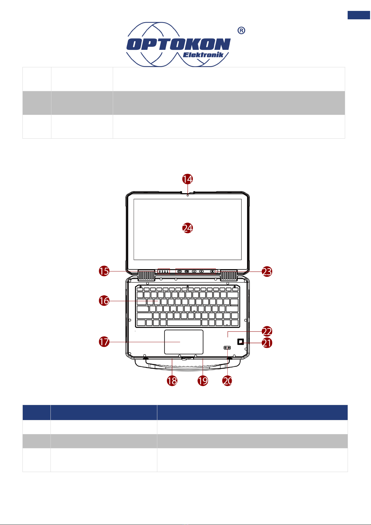
This User Manual provides information about using the OERN Series Rugged Notebook.
The documentation set includes:
• OERN Rugged Notebook Quick Start Guide - describes how to get the computer up and to
run.
• OERN Rugged Notebook User Manual – contains a detailed description of how to use the
device, its components, and features using the default setting.
Note:
Some pictures in this guide are samples and can differ from the actual product.

6
1. Overview
Congratulations on purchasing OERN Series Rugged Notebook.
OPTOKON Elektronik Rugged Notebook features with
• Fanless cooling system.
• Flip design for quick switching between laptop and tablet modes.
• Easy-replaceable design for keyboard.
• Removeable hard handle for easy carrying
• Dual battery with hot-swappable design for whole-day-work.
• Expansion slot supports optional 2nd removable SSD and smart card reader.
2. Package Content
Carefully remove the box and unpack your device. Please check if all the items listed below are
inside your package. If any of these items are missing or damaged contact us immediately.
Factory shipment list:
• Rugged Laptop
• Quick Start Guide
(Hardcopy)
• Adapter
• Power Cord
• Standard Batteries x 2

7
3. Product Overview
This section contains mechanical drawing of the OERN Series Rugged Notebook. Notice that this
is a simplified drawing and some components are not marked in detail.
Front Components
No
Item
Description
1
Top cover latch
Locks the top cover.
2
Detachable carrying handle
Provides a convenient way to carry the computer. Do
not use the handle if the handle is worn or damaged.
Rear Components
No
Item
Description
3
360° hinge
Quickly turn the device from a laptop into a touch-
enabled tablet PC.

8
Right-side Components
Left-side Components
No
Item
Description
11
Expansion Area
Reserved expansion slot for customization. Either for smart card
reader that accepts a smart card for additional security feature. Or
No
Item
Description
4
Audio Jack
Connects a set of headphones or headset. (Mic is only supported with
3.5mm 4-pin headset).
5
HDMI
Connects a HDMI monitor or TV set.
6
USB Type-C
High speed USB port connects to USB devices, such as USB flash
drive, mouse, keyboard, printer, etc.
Note: The USB Type-C connector follows USB 3.0 standard, which
does not support Alternate Mode (ALT) or USB Power Delivery (USB-
PD).
7
USB Type-A
USB 3.0 port connects to USB devices, such as USB flash drive,
mouse, keyboard, printer, etc.
8
USB Type-A
USB 3.0 port connects to USB devices, such as USB flash drive,
mouse, keyboard, printer, etc.
9
RJ45 Connector
Connects the LAN cable.
10
Power Jack
DC power input jack.

9
for solid-state drive, which is the mass storage device of the
computer. Or USB 3.0 x 1 or PCI-E x 4 or Power 5V/1A.
12
RS232
Interface that enables the connection of a serial device to a
computer.
13
USB Type-A
USB 3.0 port connects to USB devices, such as USB flash drive,
mouse, keyboard, printer, etc.
Top-open Components
No
Item
Description
14
Front Camera
2 Megapixel Webcam.
15
LED Indicators
Show the current status of the Battery.
16
Qwerty Keyboard with
backlight
Serves as the data input device.

10
17
Touch Pad
Serves as the pointing device of the computer.
18
Docking Connector (Optional)
Port to docking solutions such as vehicle docking.
19
Antenna Passthrough
(Optional)
To enhance wireless connections GPS, WLAN, WWAN
via powerful high-gain antennas.
20
Rear Camera (Optional)
8MP Autofocus camera with LED light to capture
photos and videos.
21
Fingerprint Scanner (Optional)
Serves as the fingerprint verification, preventing
unauthorized access.
22
HF RFID Reader (Optional)
Reads data from HF RFID tags.
23
Physical Buttons
2x Programmable function keys Fn1 and Fn2,
brightness, and power buttons.
24
13.3” / 14” P-Cap Touch
Screen
Displays the output of the computer with touchscreen
feature.
LED Indicators
Icon
Indicator
Description
Power Indicator
Blue– Laptop is ON
No light– Laptop is OFF
Battery Status
Orange–AC adapter is plugged in and charging
Green–AC adapter is plugged in and the battery is fully charged
Solid Red - Low battery (<10%)
Blinking Red – Battery is hot-swapped.
No light – Battery is in use, and more than 10%
Drive Indicator
Green - Disk is active
No light - Disk is idling
RF Communication
Green - One of WLAN/BT/WWAN/GPS is ON
No light - WLAN/BT/WWAN/GPS are all OFF

11
Bottom Components
No
Item
Description
25
Battery Latch
To eject the battery, for replacing battery.
26
Battery Lock
To securely enable the battery.
27
Service Window
To allow user to swap the module easily. Choices
are: 4G LTE/ WLAN/ RAM.
28
Battery 1
Supplies power to computer when external power
is not connected
29
Battery 2
Supplies power to computer when external power
is not connected
30
Micro SD Card Slot
Service window to insert Micro SD card.
31
Nano SIM Card Slot
Service window to insert Nano SIM card.

12
4. Mechanical Dimension
5. Hardware Installation
5.1 Side Expansion Area
You can add the following option: Smart Card Reader + Removable 2nd SSD
Inserting an option to the expansion area:
Important:
We recommend user to turn off the computer completely by following:
1. Click Start à Settings à Update & Security à Recovery.
2. Click Restart now.
3. Click Turn off your PC.
1. Turn off the computer and disconnect the AC adaptor. Make sure no foreign objects are under
the computer.
2. Locate the Expansion slot lock latch and push it to the “Unlock” position. Pull open the
expansion door.

13
3. Insert an option to the expansion area. Close the expansion slot door and lock the latch.
Removing an option from the expansion area:
1. Turn off the computer and disconnect the AC adaptor. Make sure no foreign objects are under
the computer.
2. Locate the Expansion slot lock latch and push it to the “Unlock” position. Pull open the
expansion door.

14
3. Pull out the option from the expansion area.
4. Close the expansion slot door and lock the latch.

15
5.2 Installing a Micro SD Card
Your laptop supports up to 2TB additional storage with an optional microSD card slot.
Important:
• Do not remove or insert the microSD card until Windows has completed loading.
• Do not remove the card or turn off the computer in the following cases, otherwise
the data may be corrupted.
o While the computer is in sleep.
o While data is being read from or written to the card.
o Immediately after the writing operation, this computer may still continue to
access to the card. If you remove the card before the operation is completed,
the data may be damaged or the card access may no longer be performed
normally.
• Note that OPTOKON Elektronik assumes absolutely no liability for any loss of
data recorded by the user, or any other damages, direct or indirect.
• Keep microSD cards away from infants and small children.
To insert the Micro SD Card:
1. Remove the right battery, as described in section 1.6.1 Installing and Removing the Battery.
2. Insert microSD card into slot with contacts facing down.
3. Press the card in to ensure that it is seated properly.
4. Put the battery back.

16
To remove Micro SD Card:
1. Save the data and close all applications.
2. Disable the card: click on the task tray, then click . Select the card.
Note:
This step is unnecessary when the computer is off, or, is not displayed, or the
card does not appear in the list.
3. Remove the right battery, as described in section 1.6.1 Installing and Removing the Battery.
4. Push and release the microSD card to unlock it.
5. Pull out the microSD card.
6. Put the battery back.
6. Battery
6.1 Installing and Removing the Batteries
Important:
• The battery pack is not charged when you first purchase it. Be sure to charge it
before using for the first time. Charging starts automatically when the AC adaptor
is connected to the computer.
• Use only the specified battery pack with your computer.
• If the computer is wet, wipe them off and open the cover. Make sure to dry off the
computer, replace/remove the battery pack.
To install the standard battery pack:
1. Disconnect any cords connected to the computer.
2. Turn the laptop over, bottom part is facing up. Make sure no foreign objects are under the
computer.
3. Locate the Battery Lock Latch and push it to the “Unlock” position.
4. Insert the battery with the connector-pins side first, and then lower the battery into the
battery compartment.
5. Push completely until the battery locks into place.
6. Slide the battery latch to the lock position to secure the battery.
7. Repeat step 3 to 6 to insert the second battery.

17
To remove the battery pack:
1. Shut down the laptop (or put into sleep mode). Disconnect any cords connected to the
computer.
2. Turn the laptop over, bottom part is facing up. Make sure no foreign objects are under the
computer.
3. Locate the Battery Lock Latch and push it to the “Unlock” position.
4. Locate the Battery Release Slider that is spring-loaded. Pull back and hold.
5. Lift the battery out using the opening on the side of the battery compartment.
6. Repeat step 3 to 5 to insert the second battery.
Important:
• When hot-swapping the battery, replace it quickly according to the level of
batteries in use.
• Make sure the latches are securely locked, otherwise the battery pack may fall
when you carry the computer.
• Do not remove the battery pack forcibly when the latches are locked. Doing so
may damage the battery pack.
6.2 Important Battery Tips
6.2.1 How to Use Battery with Minimal Deterioration
The battery performance is normally deteriorated over time. But the deterioration can be accelerated
due to the battery is used, charged, or stored in a place with high temperature or repeatedly charged.
To reduce the deterioration and ensure longer battery life, you must reduce the number of charges
and ensure that the temperature inside the battery does not become too high. If battery deteriorates,
be sure to replace with a new and specified battery pack.

18
• Do not charge the battery inside a vehicle with all its windows closed and exposed to the hot
sun or in other high temperature places. Charge the battery in a temperature range of 10 °C
to 30 °C (50 °F to 86 °F).
• Recharge the battery no more than once a day or when the remaining charge drops to <10%.
• Charge the battery when the computer is powered off to keep the temperature inside the
battery.
6.2.2 Operating the Computer to Maximize the Battery Operation Time
• Leave computer off when it is not in use
• Decrease the internal LCD brightness by pressing Fn + ↓.
• Before stepping away from your computer, enter the sleep or hibernation mode to reduce
power consumption.
• Avoid the use of screen saver or applications that will drain the CPU.
• Remove peripheral devices (USB devices, external mouse, etc.) when not in use.
• When the network communication is not working, turn off the wireless LAN.
6.2.3 When the Computer Is Inactive for a Long Period of Time
To maintain the battery performance, when not used for a long period (several months or more),
remove the battery with a remaining charge of 30% to 40% from the computer and store in a cool
and dark place, within the range of 10 °C to 30 °C (50 °F to 86 °F).
6.2.4 Notices While Using the Battery Pack
• Do not touch the terminals on the battery pack. If the terminals are dirty or damaged, it will
hinder the computer operation and battery performance.
• To charge the battery quicker, power the computer off or put it in sleep or hibernation mode.
• The battery discharges faster and charge longer in low temperature environments.
7. Turning On/Off
7.1 Turning On the Computer
Note:
• Do not press the power switch repeatedly.
• The computer will forcibly be turned off if you press and hold the power switch for
ten seconds or longer.
• Once you turn off the computer, wait for ten seconds or more before you turn on
the computer again.

19
• Do not perform the following operation until the drive indicator turns off.
o Connecting or disconnecting the AC adaptor
o Pressing the power switch
o Touching the keyboard, touchpad, touchscreen or external mouse.
o Closing the display.
1. Open the top cover by pushing the cover latch and lifting up the cover.
2. Press the power button in the keyboard or physical buttons. The Windows operating
system should start.
Other manuals for OERN-13
1
This manual suits for next models
1
Table of contents
Other OPTOKON Laptop manuals
Popular Laptop manuals by other brands

Lenovo
Lenovo ThinkPad T400s Podręcznik obsługi i rozwiązywania problemów

Asus
Asus P2451FA E-manual

Lenovo
Lenovo ThinkPad X131e Hardware Maintenance Manual

Dell
Dell Inspiron 600m Setup guide

Lenovo
Lenovo ThinkPad T431s Safety, warranty, and setup guide

Lenovo
Lenovo ThinkPad X1 Carbon Felhasználói kézikönyv

HP
HP Notebook user guide

Fujitsu Siemens Computers
Fujitsu Siemens Computers AMILO Desktop L Series operating manual

HP
HP Dv7-2270us - Pavilion Entertainment - Core 2 Quad... manual

Justice Tech Solutions
Justice Tech Solutions Securebook 5.0 manual

Lenovo
Lenovo ThinkPad T420 Maintenance manual

MySN
MySN w350et Service manual