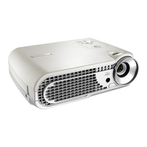
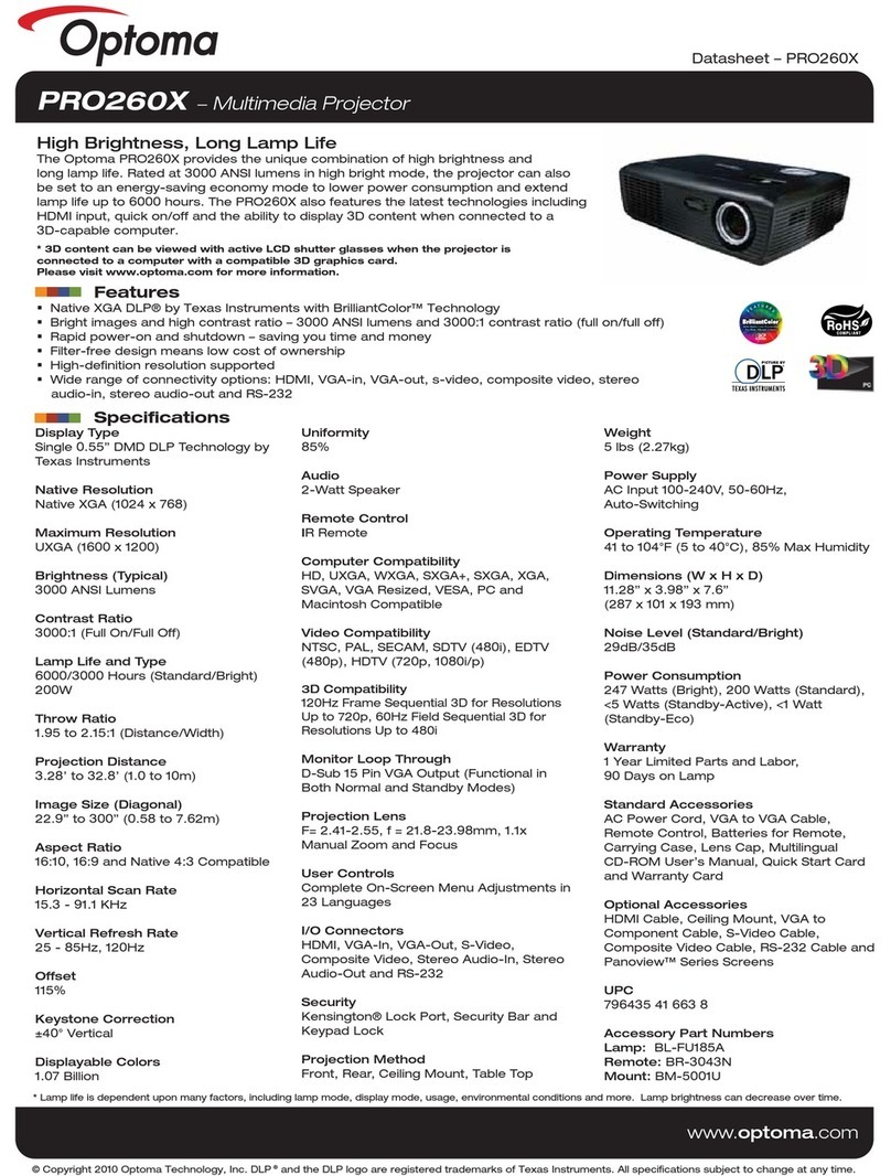
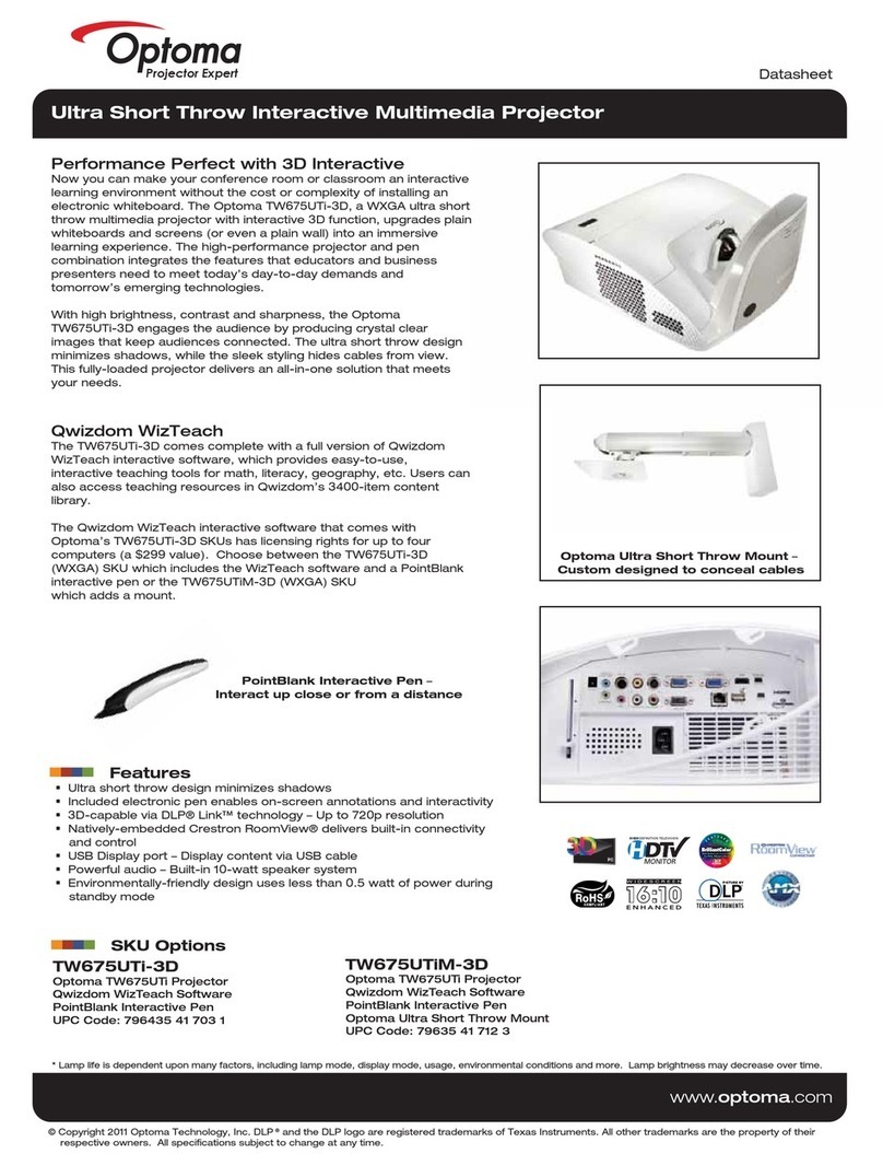
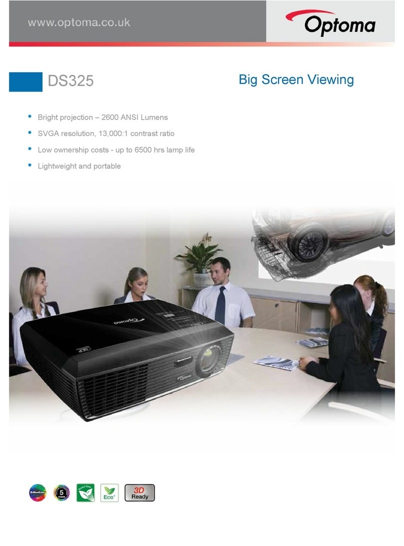
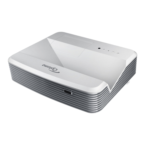
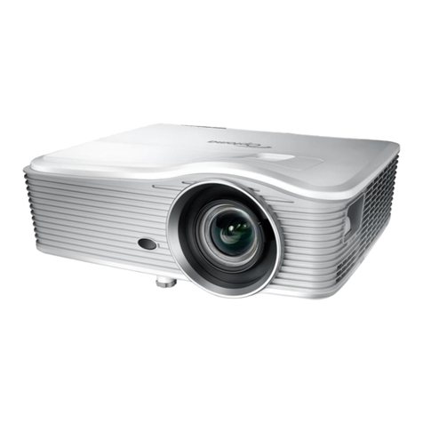
Optoma H79 User manual

ModelName:H79
SERVICEMANUAL
Date Revise Version Description
2005/3/9 V1.0 Initial Issue
Prepared bySI:
________________________________________
Prepared byTSE :Jack
________________________________________
Checkby:
________________________________________
Approved by:
________________________________________
CopyrightMarch,2005 .All RightsReserved
Document#81E-G04-01A.P/N:36.81E03.001

ThismanualisappliedtoH79ProjectorwithdigitalimagingfunctionalitybasedonDigitalMicro-mirror
Device(DMD)technology. It’sthemodeofsinglePanel,250wattPhilipsUHPlamp. Themanualgives
youabriefdescriptionofbasictechnicalinformationtohelpinserviceandmaintainingtheproduct.
Yourcustomerswillappreciatethequickresponsetimewhenyouimmediatelyidentifyproblemsthatoccur
withourproducts. Weexpectyourcustomerswillappreciatetheservicethatyouofferthem.
Thismanualisfortechniciansandpeoplewhohaveanelectronicbackground. Sendtheproductbackto
thedistributorforrepairinganddonotattempttodoanythingthatiscomplexorisnotmentionedinthe
troubleshooting.
NOTICE:
Theinformationfoundinthismanualissubjecttochangewithoutpriornotice.Anysubsequentchanges
madeinthedatahereinwillbeincorporatedinfurtheredition.
Copyright2005,March
AllRightsReserved
ManualVersion1.0
Document# 81E-G04-01A
Preface
H79I

H79II
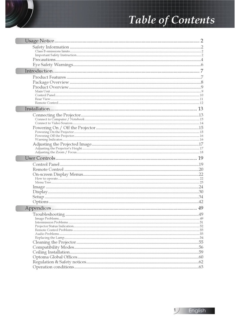
TableofContents
Chapter1Introduction 1-1
ProductHighlights1-1
ComputerCompatibility1-4
Chapter2DisassemblyProcedure 2-1
ToolsNeeded 2-1
Removing LampModule 2-2
Removing I/O Panel,Top Coverand Keypad Board 2-3
RemovingThermalBoard,MainBoard,
ConnectorBoardand PowerModule 2-5
RemovingBallastModule,FrontCoverand Engine Module 2-7
Removing FanModule92x25mm,DMDChip,Fan Module
50x15mm,FanModule59x25mm,ThermalSensor2-9
RemovingAirDuctModule 2-13
Chapter3Troubleshooting 3-1
EquipmentNeeded 3-1
MainProcedure 3-2
Chapter4Function Testand AlignmentProcedure 4-1
Product4-1
TestEquipment4-1
TestCondition 4-1
TestDisplayModesand Pattern 4-2
InspectionProcedure 4-6
Chapter5FirmwareUpgradeProcedure 5-1
EquipmentNeeded 5-1
Setup Procedure 5-1
FirmwareUpgrade Procedure 5-2
HotKey5-5

Chapter6DDC Key-inProcedure 6-1
EquipmentNeeded 6-1
HardwareSetup Procedure 6-2
EDIDUpgrade Procedure 6-3
AppendixAExplodedOverview7-1
AppendixBSerialNumberSystemDefinition 7-19
Reader’s Response 7-20

H791-1
+D=FJAH
Introduction
1-1 Product Highlights
- One HD2 2.5G 0.79" DMD projection system with 540 ANS lumens.
- Contrast (FOFO) : 2800 : 1 (Typical), 2400:1 (Minimum)
-250 - Watt Philips UHP Lamp. Lamp life 1500 hours, Eco mode 2000 hours
- High efficiency cooling system with system acoustic noise level 32 +/- 2 dB(A) (Normal-mode) / 28
+/- 2 dB (A) (Eco- mode)
- Lens Up/Down Shift construction
- Adjustable Feet ( +/- 3 degrees)
- Dimensions : 430mm x 305mm x 135mm (External Max size)
- Motorized focus projection and zoom lens 1.35X
- 8 segments GgRBGgRB color wheel spinning at 150Hz
- Computer capability up to UXGA 60Hz for Analog and XGA 75Hz for Digital nputs
- NTSC/PAL/SECAM video capability with S-video / composite / component, and HDTV(480i/p,
576i/p, 720p, 1080i)
- Separately R/G/B/H/V BNC input supported.
- Auto detection of computer signal input(Auto-tracking /frequency /position adjustment).
- Source Lock Feature
- Automatically saves adjustments for future use
- On-screen menu with 10 languages
- On Screen lamp life timer.
- One DV PC-data input ( ncluding Analog and Digital RGB signal )
- Support HDCP function
- R remote controller
- No High Altitude Mode function supports in OSD

H791-2
- Weight : < 17.1 lbs. ( 7.8 Kg )
- Cooling System
a. Advanced Air Flow
Three fans with system acoustic noise level : 32dB(A) (Typical)
Temperature control circuits with adaptive voltage control fan speed
b. Max touch temperature follows UL60950 regulation
- Lamp Door Protection : Lamp power supply shuts off automatically when door opens
- Display Panel Specifications
a. T HD2+ DC3 (Dark Chip 3) 0.79 DMD / 12deg / 1280x720
b. Number of active dots : 1280(H) x 720(V)
- Power Supply :
Universal AC 90264V~50-60 Hz with PFC input
250W for Philips UHP Lamp at normal operation
- Power consumption
330W+/-10% (Operating@110V), 3.08A+/-10% (Operating@110V)
13.5W maximum (Stand-by@90V), 25W maximum (Stand-by@264V)
- /O ports
a. DV x 1 (DV ,Analog RBG, Component, HDTV)
b. BNC RBGHV x 1 ( R x 1, G x 1, B x 1, Hsync x 1, Vsync x1)
c. YCbCr x1 (R x 1, G x 1, B x 1)
d. Video input (RCA jack Type X 1)
e. Mini D N 4-pin X 1 (S-video)
f. R x 2 (Front, Rear)
g. RS232 Serial Control x 1 (D-sub)
h. Power Cord x 1
i. 12V Trigger relay x 2
- nput signal spec.
a. Hsync Frequency 31.5 ~ 91.1 kHz
b. Vsync Frequency 43 ~ 85 Hz
c. Video Signal RGB (PC)
Analog RGB 0.7Vp-p, 75 ohm
Analog RGB 1Vp-p, 75 ohm, Sync. Signal
Separate TTL H,V Sync.
Composite TTL Sync.
d. Video
Composite video 1Vp-p,75 ohm
S-video Luminance 0.714Vp-p,75 ohm
S-video Chrominance 0.286Vp-p,75 ohm

H791-3
- nput signal spec.
a. Hsync Frequency 31.5 ~ 91.1 kHz
b. Vsync Frequency 43 ~ 85 Hz
c. Video Signal RGB (PC)
Analog RGB 0.7Vp-p, 75 ohm
- Video Compatibility
a. Standards :
NTSC - M, 4.43 MHz
PAL - B, D, G, H,
SECAM - B, G, H, K, K1, L
HDTV - 480i, 480p, 576i, 576p, 720p, 1080i
b. TV Lines - 500 lines
- Keystone
a. Vertical : +/- 16 degree (Desk-projecter angle)
b. Horizontal : +/- 7 degree (Screen-projecter angle)
- Projection lens : f = 28.3 ~ 38.2mm, F/3.4, 1.35X Manual Zoom Lens.
- Projection mage Size : 30 to 280 Diagonal (Wide)
- Throw Distance : 3.28 ft to 32.80 ft / 1.0m to 10m(Wide).
- Throw Ratio : 1.6~2.16 (Projection Distance/ mage Width)
- Brightness : 540 ANS lumens
- Temperature
a. Operating : 5°C 35°C
Storage: -10°C 60°C
- Maximum Humidity
a. Operating: 5°C 35°C , 80%RH (Max.), non-condensing
Storage: -10°C 60°C , 80%RH (Max.), non-condensing
- Lamp life :
a. 1500 hours min. , 50% survial rate (Normal mode)
2000 hours min. , 50% survial rate (Eco mode)
( Lamp life = normal lamp life+1/2 Eco lamp life )
- Altitude :
a. Operating : 0~2,500 ft 5°C~35°C
2,500~5,000 ft 5°C~30°C
5,000~10,000 ft 5°C~25°C
Storage : 40,000 ft
- MTBF : Operating more than 12,000 hrs (90% confidence level)

H791-4
1-2 Computer Compatibility
Compatibility Resolution V-Sync [Hz] H-Sync [KHz]
VGA 640x4 0 60 31.5
640x4 0 72 37.9
640x4 0 75 37.5
640x4 0 5 43.3
720x400 70 31.5
720x400 5 37.9
SVGA 00x600 56 35.2
00x600 60 37.9
00x600 72 4 .1
00x600 75 46.9
00x600 5 53.7
XGA 1024x76 43.4 35.5
1024x76 60 4 .4
1024x76 70 56.5
1024x76 75 60.0
1024x76 5 6 .7
SXGA 12 0x1024 60 64
12 0x1024 75 0
12 0x1024 5 91.1
UXGA 1600x1200 60 75
a. Analog
b. Digital
Compatibility Resolution V-Sync [Hz] H-Sync [KHz]
VGA 640x4 0 60 31.5
640x4 0 72 37.9
640x4 0 75 37.5
640x4 0 5 43.3
700x400 70 31.5
700x400 5 37.9
SVGA 00x600 56 35.2
00x600 60 37.9
00x600 72 4 .1
00x600 75 46.9
00x600 5 53.7
XGA 1024x76 60 4 .4
1024x76 70 56.5
1024x76 75 60.0

H792-1
Chapter 2
Disassembly Procedure
Tools Needed
Screw Bit (+) : 107
Screw Bit (+) : 102
Hex Sleeves 5mm
Long Nose Nipper
Angle utting Nipper
Ball-end hex-key 3mm

H792-2
2-1 Removing Lamp Module
1. Unscrew one screw to remove the Lamp over.
Note : Be careful that Lamp over has the tenon inside.
2. Loosen 3 screws to remove Lamp Module.
Lamp over
Lamp Module

H792-3
1. Unscrew 4 hex screws to remove I/O Panel.
2. Unscrew 8 hex screws and 3 screws, then unplug one FP cable to remove Top over.
2-2 Removing I/O Panel, Top Cover and Keypad oard
3 screws
I/O Panel

H792-4
3. Unplug one FP cable and unscrew 9 screws to remove Keypad Board, Keypad and Lens
Shift Gear Module.
Keypad Board
Keypad
Lens Shift Gear Module
4. Unscrew 8 screws to remove Shielding Top.
Shielding Top
Holder Bracket

H792-5
1. Unplug 9 connector cables and unscrew 2 screws to remove Thermal Board.
2-3 Removing Thermal oard, Main oard,
Connector oard and Power Module
2. Unscrew 4 screws to remove onnector Board.
Unscrew 9 hex, unplug one connector cable and one FP cable to remove Main Board.
3. Unscrew 8 screws and unplug 3 connector cable to remove Power Module.
Power Module
onnector Board
connector
cable
FP
cable

H792-6
4. Unscrew 4 screws to remove Lamp Housing Holder.
Lamp Housing Holder
5. Remove the power panel, then unscrew 2 screws to remove Power Board.
6. Unscrew 3 screws to remove I/O Bracket Module.
I/O Bracket Module
Thermal
Sensor
Board

H792-7
1. Unscrew 4 screws from Ballast and 2 screws from Lamp Housing.
2-4 Removing allast Module, Front Cover and
Engine Module
2. Unscrew 3 screws to remove Top over.

H792-8
3. Unscrew 8 screws to remove Ballast Module and Engine Module.
Ballast Module
Engine Module

H792-9
1. Unscrew 4 screws to remove Fan Module(92x25mm) from Engine Module.
2-5 Disassemble Engine Module
(Removing Fan Module 92x25mm, DMD Chip, Fan Module
50x15mm, Fan Module 59x25mm, Thermal Sensor
2. Unscrew 8 screws and one FP cable to remove DMD Hestsink and Formatter Board.
DMD Hestsink
Formatter Board
one FP cable

H792-10
3. Unscrew 3 screws to remove Formatter Board Shielding.
Formatter Board Shielding
4. Unscrew 3 screws to remove DMD hip.
DMD hip

H792-11
5. Unscrew 2 screws to remove Fan Module (50x15mm).
6. Turn over the Engine Module, then unscrew 2 screws to remove Fan (59x25mm).
Unscrew one screw to remove Thermal Sensor Board.
Sensor Board

H792-12
7. Unscrew one screw to remove Thermal Switch.
Thermal Switch
Other manuals for H79
3
Table of contents
Other Optoma Projector manuals

Optoma
Optoma DW326e User manual

Optoma
Optoma TX779P-3D User manual

Optoma
Optoma ML330 User manual

Optoma
Optoma EX531p User manual

Optoma
Optoma EH505 User manual

Optoma
Optoma Optoma EX525ST User manual

Optoma
Optoma Optoma EP7155 User manual

Optoma
Optoma TW766W User manual

Optoma
Optoma ZH506 User manual

Optoma
Optoma X316 User manual

Optoma
Optoma EH400 User manual

Optoma
Optoma ES522 User manual

Optoma
Optoma DH1011i User manual

Optoma
Optoma H78DC3 User manual

Optoma
Optoma HD2200 User manual

Optoma
Optoma GT700 User manual

Optoma
Optoma TS542 User manual

Optoma
Optoma ZU720T User manual

Optoma
Optoma HD808 User manual

Optoma
Optoma ZW502 User manual