ORANGE MGH 412 SE User manual

MANUALDEUSUARIO
COCINAENCIMERA
MODELO:MGH412SE(AceroInoxidable)
MODELO:MGH412GC(VidrioTemplado)
ES COCINAENCIMERA
-
MANUALDELUSUARIO
GB HOB-USERMANUAL
MANUAL DE USUARIO
COCINA ENCIMERA
MODELO:MGH 412 SE (Acero Inoxidable)
MODELO:MGH 412 GC (Vidrio Templado)
ES COCINA ENCIMERA
-
MANUAL DEL USUARIO
GB HOB-USER MANUAL

1
Estimado Cliente,
Le agradecemos mucho y lo felicitamos por su elección.
Este nuevo producto, cuidadosamente estudiado y fabricado con materiales de primera calidad,
ha sido probado esmeradamente para poder satisfacer todas sus exigencias de una perfecta
cocción.
Por lo tanto, le rogamos lea y respete las fáciles instrucciones que le permitirán llegar a
resultados excelentes desde la primera utilización.
Con este moderno aparato le expresamos nuestras mejores felicitaciones.
EL FABRICANTE
ÍNDICE
I. MODELOS QUE INCLUYEN PILAS
Garantía
Paquete
Instalación y eficiencia
II. INSTRUCCIONES PARA EL SUSUARIO
Instalación
Utilización
Mantenimiento
III. INSTRUCCIONES PARA EL INSTALADOR
Instalación
Colocación
Conexión gas
Conexión eléctrica
Características inyectores
ESTE PRODUCTO FUE CONCEBIDO PARA UN USO DE TIPO DOMÉSTICO. EL
FABRICANTE DECLINA CUALQUIER RESPONSABILIDAD EN EL CASO DE DAÑOS
EVENTUALES A COSAS O PERSONAS QUE DERIVEN DE UNA INSTALACIÓN
INCORRECTA O DE UN USO IMPROPIO, ERRADO O ABSURDO
ES
2
I. MODELOS QUE INCLUYEN PILAS
Garantía
La garantía (servicio de garantía) no cubre las pilas.
El fabricante de la placa de gas está exento de responsabilidad alguna por fallos de las pilas.
Paquete
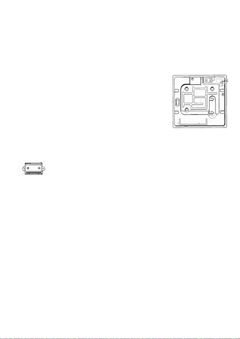
Algunos modelos incluyen pilas (tipo D o LR20 o R20S; 1,5V) para la
función de autoencendido. Compartimento (dispositivo) para instalar la pila
situado en la parte trasera inferior izquierda de la placa, representado en la
figura.
Si la pila no está incluida, hay que comprarla por separado.
Instalación y eficiencia
Antes de instalar la cocina encimera en un tablero, insertar una pila (prestando atención a la orientación
de los polos «+» y «-») en el dispositivo especial situado en la parte trasera inferior izquierda de la
cocina encimera, representado en la figura.
Antes de fijar la cocina encimera en un tablero de forma definitiva con sellante especial (relleno) con
base adhesiva (incluida), asegurarse de que el autoencendido funciona correctamente. Para ello,
presionar cualquier botón y girarlo en sentido contrario a las agujas del reloj de forma que la marca
señale hacia el símbolo de la llama. Esperar a que se produzcan chispas seguidas de los característicos
sonidos crepitantes.
Si el autoencendido no funciona bien, comprobar si la pila está desgastada y cambiarla.
Si el problema persiste, llamar al Servicio de Atención al Cliente o al de mantenimiento.
II. INSTRUCCIONES PARA EL USUARIO
Instalación
Todas las operaciones relativas a la instalación (conexión eléctrica) tienen que ser efectuadas por
personal calificado según las normas vigentes.
Para las instrucciones específicas, véase la parte reservada al instalador.
Utilización
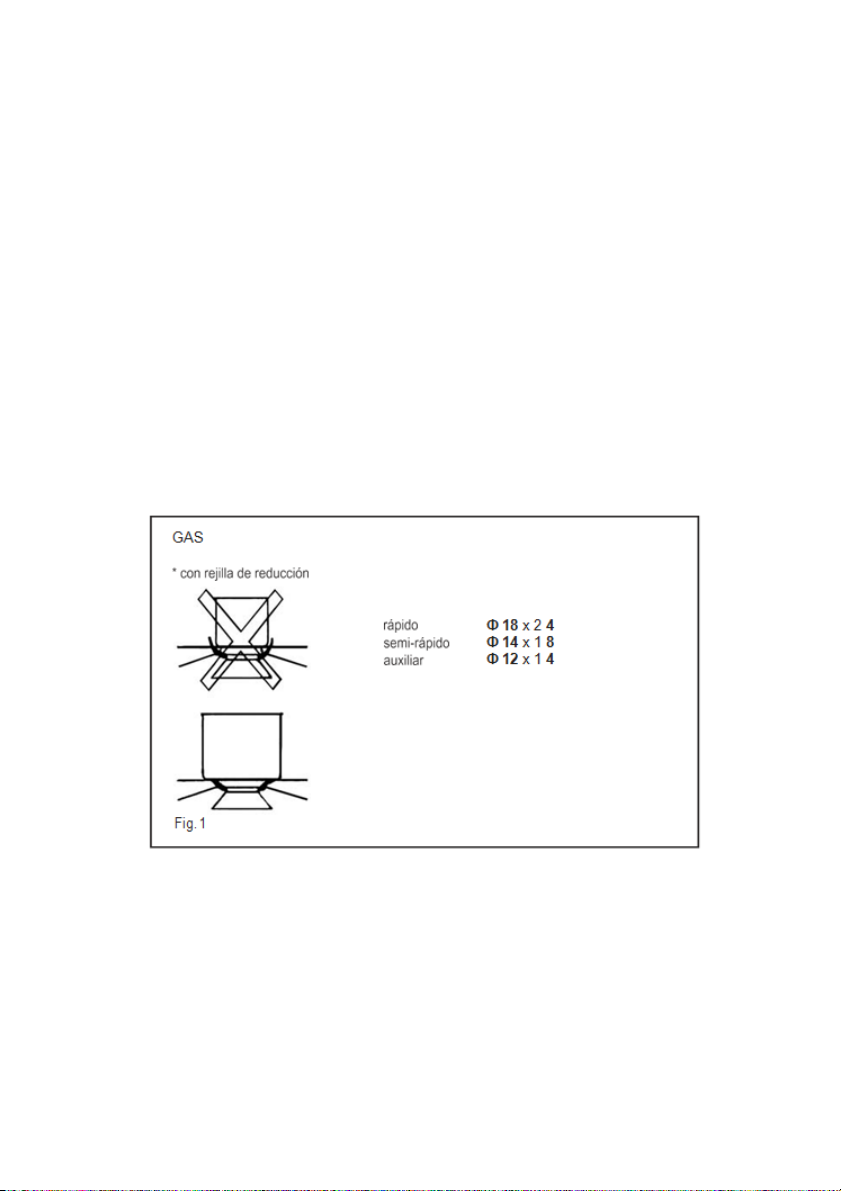
Quemadores de gas (Fig.1)
El encendido del quemador tiene lugar acercando una llama a los agujeros de la parte de arriba del
mismo quemador, presionando y girando en sentido antihorario la perilla correspondiente hasta que su
indicador coincida con la posición de máximo. Una vez efectuado el encendido regular, ajustar la llama
según la necesidad. La posición de mínimo está al final de la rotación antihoraria.
3
En los modelos con encendido automático, actuar sobre la perilla como se describe arriba, presionando
simultáneamente el botón de empuje. En los modelos con encendido automático / simultáneo (con una
mano) es suficiente accionar el mando respectivo como se indicó anteriormente.
La descarga eléctrica entre bujía y quemador provoca el encendido del quemador. Una vez efectuado el
encendido soltar inmediatamente el pulsador regulando la llama según la necesidad.
El encendido de los quemadores en los modelos con seguridad termoeléctrica se efectúa como en los
casos ya descritos, manteniendo el mando presionado a fondo en la posición de máximo durante unos 3-
5 segundos. Al soltar la perilla asegurarse que el quemador permanezca encendido.
Importante:
Se aconseja utilizar sartenes de diámetro apto a los quemadores evitando que cuando la llama se
encuentre al máximo salga del fondo de las mismas.
No dejar ollas vacías con el fuego encendido.
Sobre la cocina encimera de vidrio templado, no usar herramientas para la cocción de la parrilla.
Al final de la cocción, se aconseja cerrar la tubería o balón de gas.
Mantenimiento
Gas/Eléctrico
Antes de cualquier operación, desconectar eléctricamente el aparato.
Para una mayor duración del aparato es indispensable efectuar periódicamente una cuidadosa limpieza
general teniendo en cuenta lo siguiente:
Las partes en vidrio, de acero y/o esmaltadas tienen que ser limpiadas con productos idóneos (que se
pueden encontrar a la venta) no abrasivos ni corrosivos. Eviten productos a base de cloro (lejía, etc.)
Eviten dejar sobre el tablero de trabajo substancias ácidas o alcalinas (vinagre, sal, zumo de limón,
etc.)

4
Los rompellamas y las tapaderas (partes movibles del quemador) tienen que ser lavados a menudo
con agua muy caliente y detergente teniendo el cuidado de quitar toda incrustación. Tienen que ser
secados cuidadosamente, y hay que controlar que ninguno de los agujeros de los rompellamas esté
cerrado, ni siquiera parcialmente.
Las placas eléctricas se limpian con un trapo húmedo y se engrasan ligeramente con aceite lubricante
cuando estén todavía tibias.
Las rejillas inoxidables de la superficie de cocción, después de haber sido calentadas, toman una
coloración azulada que no daña su calidad. Para que vuelvan a su apariencia original, utilizar un
producto ligeramente abrasivo.
Nota: La eventual lubricación de los grifos tiene que ser efectuada por personal calificado con el cual
se aconseja ponerse en contacto en caso de anomalías de funcionamiento.
Controlar periódicamente el estado de conservación del tubo flexible de alimentación gas. En caso de
pérdidas, solicitar la intervención inmediata del personal calificado para su situación.
Mantenimiento
Vitrocerámico
(Fig. 2) Primero, quitar los residuos de comida y las salpicaduras de grasa de la superficie de cocción.
Luego, limpiar la zona caliente con un producto limpiador de metales. Luego, aclarar con agua y secar
con un trapo limpio.
Trozos de papel de aluminio, de objetos de plástico, azúcar o comidas muy sacaríferas tienen que ser
quitadas inmediatamente de la zona caliente de cocción con una raedera para evitar posibles daños a la
superficie de cocción. En ningún caso utilizar esponjas o trapos; evitar también utilizar detergentes
químicos agresivos.
No utilice aparatos de vapor para limpiar el plano de cocción.
Fig. 2

5
III. INSTRUCCIONES PARA EL INSTALADOR
Instalación
Este aparato no tiene un dispositivo de descarga de los productos de la combustión. Se aconseja
instalarlo en locales suficientemente aireados según las disposiciones de ley vigentes. La cantidad de
aire necesaria para la combustión no tiene que ser menos que 2.0 m3/h por cada kW de potencia
instalado. Véase tabla de potencias quemadores.
Colocación
El aparato está preparado para ser empotrado en un tablero de trabajo como se ilustra en la siguiente
figura. Antes de introducir el plano, predisponer la junta de sellado sobre todo el perímetro del agujero
del empotrado.
En el caso de que el aparato no tenga el cable y/o relativo enchufe, utilizar material apto para la
absorción indicado en la placa matrícula y para la temperatura de trabajo. El cable en ningún punto
tendrá que llegar a una temperatura superior de 50°C a la temperatura ambiente.
Si se quiere una conexión directa a la red, es necesario interponer un interruptor omnipolar con abertura
mínima entre los contactos de 3mm dimensionado para la carga de placa y responder a las normas
vigentes (el cable de tierra amarillo/verde no tiene que ser interrumpido por el interruptor). El enchufe o
el interruptor omnipolar tienen que ser fácilmente alcanzables con el aparato instalado.
El fabricante declina cualquier responsabilidad en el caso de que lo dicho arriba y las usuales normas
contra los infortunios no sean respetadas.
Si el cable de alimentación está dañado, debe ser sustituido por un cable o conjunto especial a
suministrar por el fabricante o servicio post venta.
Se prohíbe la utilización de silicona para el sellado. Solo se permite utilizar la junta de estanqueidad
suministrada.
Se prohíbe el uso de ollas de barro y difusores.
Fig. 3

6
PISACABLE
Fig. 5
Conexión Gas
(Fig, 4) Conectar el aparato al balón de gas según las prescripciones de las normas vigentes
comprobando antes que el aparato esté preparado para el tipo de gas disponible. En caso contrario,
véase ”Adaptación a un distinto tipo de gas”. Además, comprobar que la presión de alimentación esté
dentro de los valores citados en la tabla “Características inyectores”.
Conexión metálica rígida/semirígida
Efectuar la conexión con rácores y tubos metálicos (también flexibles), de manera que no se provoquen
solicitaciones a los órganos interiores del aparato.
Importante: Una vez efectuada la instalación controlar, con una solución jabonosa, la perfecta
estanqueidad en todo el sistema de conexión.
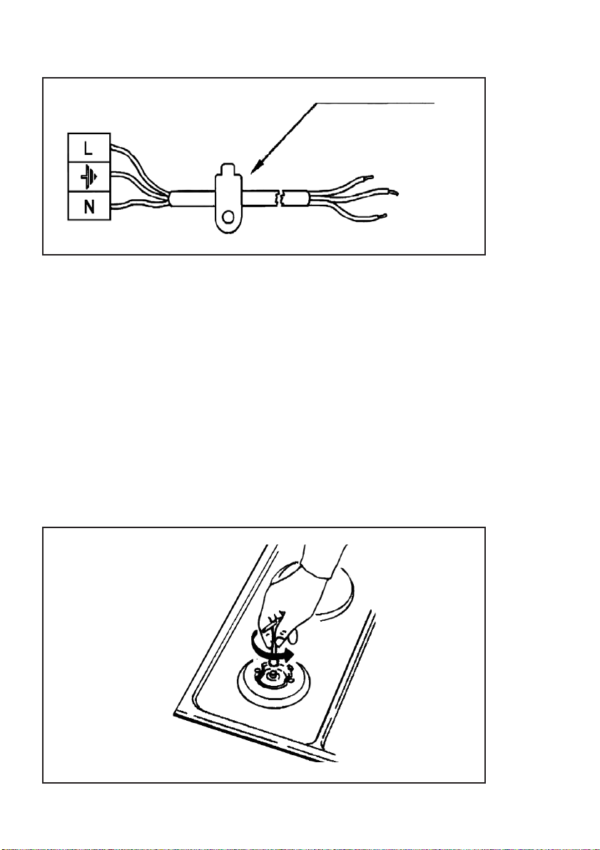
Conexión Eléctrica
(Fig. 5) Antes de efectuar la conexión eléctrica, comprobar que:
Las características de la instalación son las que se indican en la placa matriz colocada en el fondo de la
superficie de cocción.
Que la instalación tenga una eficaz conexión de tierra según las normas y las prescripciones de ley
vigentes.
La puesta a tierra es obligatoria por ley.
G 1/2
ISO 7/1
ISO 228/1 (FR)
(Fig. 4)

7
En el caso de que el aparato no tenga el cable y/o relativo enchufe, utilizar material apto para la
absorción indicado en la placa matrícula y para la temperatura de trabajo. El cable en ningún punto
tendrá que llegar a una temperatura superior de 50°C a la temperatura ambiente.
Si se quiere una conexión directa a la red, es necesario interponer un interruptor omnipolar con abertura
mínima entre los contactos de 3mm dimensionado para la carga de placa y responder a las normas
vigentes (el cable de tierra amarillo/verde no tiene que ser interrumpido por el interruptor). El enchufe o
el interruptor omnipolar tienen que ser fácilmente alcanzables con el aparato instalado.
El fabricante declina cualquier responsabilidad en el caso de que lo dicho arriba y las usuales normas
contra los infortunios no sean respetadas.
Si el cable de alimentación está dañado, debe ser sustituido por un cable o conjunto especial a
suministrar por el fabricante o servicio post venta.
Adaptación a un tipo diferente de gas
(Fig. 6) Si el aparato estuviera preparado para un tipo de gas diferente del de la alimentación disponible,
hay que efectuar:
La sustitución de los inyectores (Fig. 6) con los correspondientes al tipo de gas a utilizar (Véase tabla
“Características inyectores”).
Fig. 6

8
Fig. 8
Para la regulación del mínimo, usar un destornillador apropiado en el tornillo puesto sobre la llave
(Fig. 7) después de haberlo girado en la posición de mínimo. Para GPL (Butano / propano) atornillar
a fondo.
(cm)
R
L1
L2
L3
L4
1
6
4
10
70
Fig. 7

9
II2H3+
CARACTERISTICAS INYECTORES
QUEMADORESDEGAS
TIPO
PRESIÓN
INYECTORES
CONSUMO
CAPACIDAD TÉRMICA NOMINAL
mbar
1/100mm
g/h
l/h
Kw
Kcal/h
G 20
20
74
-
95
1,00
860
Auxiliar
G30/G31
28
51
66
-
1,00
774
G 20
20
98
-
179
1,75
1617
Semirápido
G30/G31
28
69
137
-
1,75
1617
G 20
20
114
-
190
2,50
1720
Rápido
G30/G31
28
81
145
0
2,50
2064
G 20
20
124
-
271
3,00
2451
Fast
G30/G31
28
88
248
0
3,00
2924

10
Dear customer,
We thank you and congratulate you on your choice.
This new carefully designed product, manufactured with the highest quality materials, has been carefully tested to
satisfy all your cooking demands.Wewould therefore request you toread and follow these easy instructions which will
allow you to obtain excellent results right from thestart.
May we wish you all the very best with your modern appliance!
THE MANUFACTURER
INDEX
MODELS INCLUDING BATTERIES
Warranty
Package
Installation and effciency
INSTRUCTIONS FOR USE
Installation
Use
Maintenance
INSTRUCTIONS FOR THE INSTALLATER
Installation
Gas connection
Electrical connection
Injectors characteristics
THIS APPLIANCE IS CONCEIVED FOR DOMESTIC USE ONLY.THE MANUFACTURER SHALL NOT IN ANY WAYBE
HELD RESPONSIBLE FOR WHATEVER INJURIES OR DAMAGES ARE CAUSED BY INCORRECT INSTALLATION OR
BY UNSUITABLE, WRONG OR ABSURD USE.
GB
11
INSTRUCTIONS FOR USE
Installation
All the operations concerned with the installation (electrical connection) must becarried out by qualifed technicians, in
terms with the standards in force, for specifc instructions, kindly read the part reserved for the installation technician.
Use
Gas burners(fg. 1)
The ignition ofthe gas burner is carriedoutby putting a small fame to the upper part holes of the burner,pressing
androtatingthecorrespondingknobinananti-clockwisemanner,untilthemaximumpositionhascoincidedwiththe
marker.Whenthegasburnerhasbeenturnedon,adjustthefameaccordingtoneed.Theminimumpositionisfound
at the end of the anti-clockwise rotation direction.
In models with automatic ignition, operate the knob as described above, pressing simultaneously, the corresponding
push-button. For models with automatic/simultaneous (with one hand) ignition, it is suffcient to proceed as described
above using the corresponding knob. The electric, spark, between the ignition plug and the burner provides the ignition
of the burner itselfAfter ignition, immediately release the push-button and adjust the fame according to need.
For models with a thermoelectric safety system, the burner is ignited as in the various cases described above,keeping
theknobfullypressedonthemaximumpositionforapproximately3/5seconds.Afterreleasingtheknob,makesure
theburnerisactuallylit.
N.B.:-werecommendtheuseofpotsandpanswithadiametermatchingthatoftheburner,thuspreventingthefame
from escaping from the bottom part and surrounding the pot
- donotleaveanyemptypotsorpansonthefre
- donotuseanytoolsforgrill-cookingonCrystalhobs.
When cooking is fnished, it is also a good norm to close the main gas pipe tap and/or cylinder.
GAS
* with reductiongrid
fast
semifast
auxiliary
Ф18x24
Ф14x18
Ф12x14
fsh*
18x30
Fig. 1
12
MODELS INCLUDING BATTERIES
Warranty
Warranty (warranty service) does not include the battery.
Thegashobmanufacturerisexemptofanyresponsibilityforthemalfunctionofbatteries.
Package
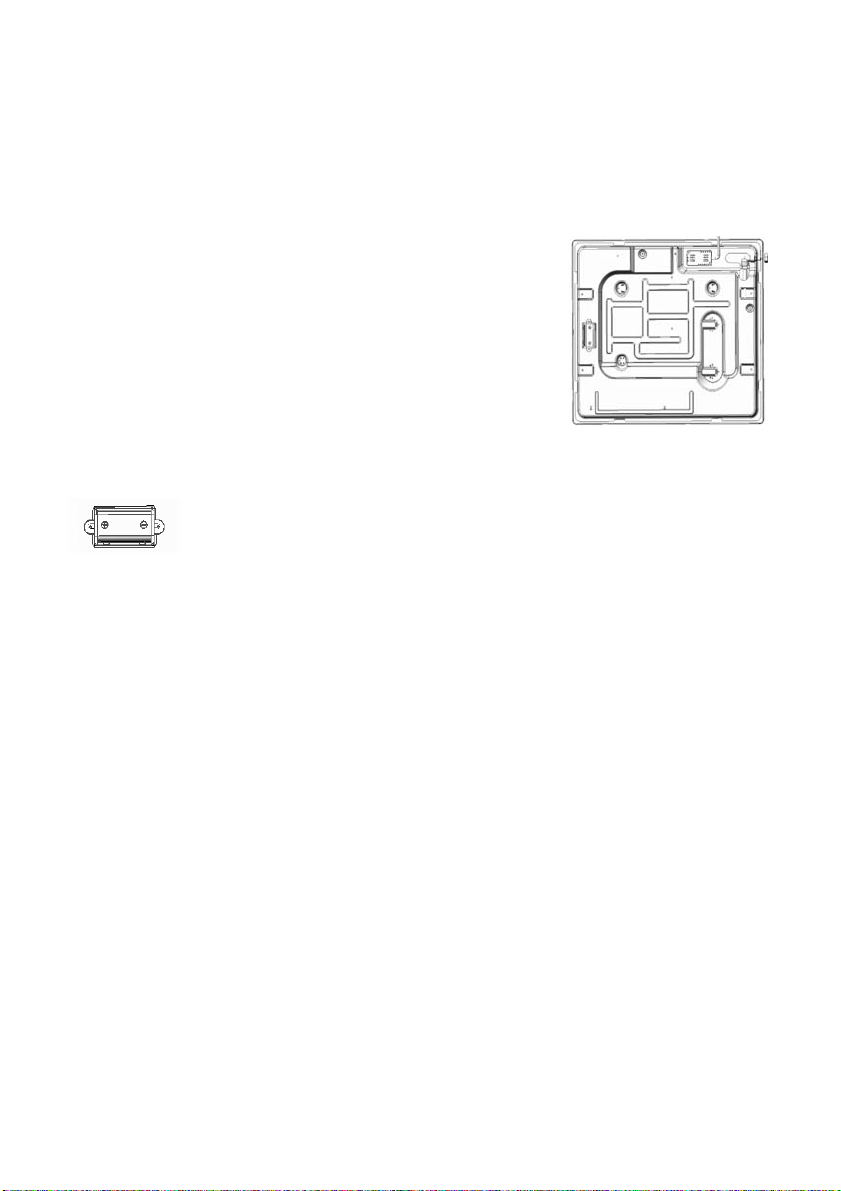
Somemodels include batteries (D or LR20 or R20S type; 1,5 V) for the
autoignition function. Capacity (device) to install the battery located at the
bottombackleftsideofthehobasshowninthepicture.
If the battery is not included and should be purchased separately.
Installation and effciency
Beforeinstallingyourhobonatabletop,frstinsertabattery(checking“+”and“-”)intoaspecialdevicelocatedatthe
bottombackleftsideofthehobasshowninthepicture.
Before fnal fxation ofthe hob in a tabletop with special sealer (liner) with adhesive basing (included) make sure
autoignitionworkscorrectly.Inordertodoit,pushanyknobturningitcounterclockwisesothatitsindexpointsatthe
fame symbol waiting until there are sparks followed by characteristic cracks (clicks).
Incasethatautoignitiondoesn’tworkproperly,checkifbatteriesareunloadedandproceedtochangeit.
If problems aren’t solved, call the Customer Service or maintenance.
Maintenance
Gas/Electrical
Prior to any operation, disconnect the appliance from the electrical system.
For long-life to the equipment, a general cleaning operation must take place periodically, bearing in mind the following:
•
the glass, steel and/or enamelled parts must be cleaned with suitable non-abrasive or corrosive products (found on
the market). A void chlorine-base products (bleach, etc.);
•
avoid leaving acid or alkaline substances on the working area (vinegar, salt, lemon juice, etc.).
•
thewallbaffeandthesmallcovers(mobilepartsoftheburner)mustbewashedfrequentlywithboilingwaterand
detergent, taking care to remove every possible encrustation. Dry carefully and check that none of the burner holes
isfullyorpartiallyclogged;
•
theelectricalpartsarecleanedwithadampclothandarelightlygreasedwithlubricatingoilwhenstillwarm.
•
thestainlesssteelgridsof theworkingarea,afterhavingbeenheated,takeonabluishtintwhichdoesnot
deterioratethequality.Tobringcolourbacktoitsoriginalstate,useaslightlyabrasiveproduct.
N.B.:- Cleaning of the taps must becarried out by qualifed personnel, who must be consulted in case ofany fmctioning
anomaly.
Check periodically the state ofconservation of the fexible gasfeed pipe. In case of leakage, call immediately the
qualifed technicians for itsreplacement.

13
Maintenance vitroceramic surface
(Fig.-2)Firstofallremovestrayfoodbitsandgreasedropsfromthecookingsurfacewiththespecialscraper(fg.2).
ThencleanthehotareaasbestaspossiblewithSIDOL,STAHLFIXorothersimilarproductswithapapertowel,then
rinseagainwithwateranddrywithacleancloth.
Pieces of aluminum foil andplastic material which haveinadvertently melted or sugarremains or highly sacchariferous
foodhavetoberemovedimmediatelyfromthehotcookingareawiththespecialscraper(fg.2).Thisistoavoidany
possible damage to the surface of the top.
Undernocircumstancesshouldabrasivespongesorirritatingchemicaldetergentsbeusedsuchasovenspraysor
spotremovers.
Do not use steam cleaning appliances to clean the cooking surface.
INSTRUCTIONS FOR THE INSTALLER
Installation
This appliance isnot provided with acombustion product discharge. Itisrecommended that itbeinstalled insuffciently
aerated
places,intermsofthelawsinforce.Thequantityofairwhichisnecessaryforcombustionmustnothebelow
2.0
m
3
/h
for
each
kW
of
installed
power.
See table of burner power.
Positioning
The appliance can be ftted into a working area as illustrated on the corresponding fgure. Before positioning the hob,
ftthesealaroundtheentireperipneryoftheholecutintheworktop.
Fig. 2
Fig. 3

14
•
thattheplantisfttedwithaneffcientearthconnection,followingthestandardsandlawprovisionsinforce.
The earth connection is compulsory in terms of the law. Should there be no cable and/or plug on the equipment,
use suitable absorption material for the working temperature as well, as indicated on the matrix plate. Under no
circumstancemustthecablereachatemperatureabove50 Coftheambienttemperature.
Should a direct connection to the network be required, it will benecessary to interpose anomnipolar switch with
minimumaperturebetweenthe3mm.contacts,dimensionedtobeartheplateloadanditmustfollowthestandards
inforce(theyellow/greenearth cablemustnotbeinterruptedbytheswitch).Theplugor omnipolarswitchmustbe
easily reached on the installed equipment.
Themanufacturersdeclineanyresponsibilityin theeventofnon-compliance withwhatisdescribedaboveandthe
accident prevention norms not being respected and followed.
If the mains cable becomes damaged,replace itimmediately with a cable or special cable set obtained from the
manufacturer or from after sales service.
Theuseofsiliconeforthesealingisprohibited.Itisonlypermittedtousethesealprovided.
Theuseofclaypotsandheatdiffusersisprohibited.
GAS CONNECTION
(Fig.4)Connecttheappliancetothegascylinderortotheinstallationaccordingtotheprescribedstandardsinforce,
andensurebeforehand,thattheappliancematchesthetypeofgasavailable.Otherwise,see“Adaptation tovarious
typesofgas”. Furthermore, check that the feed pressure falls within the values described on the table:“Injectors
characteristics”.
Rigid/semirigid metal connection
Carryoutthe connection with fttings and metal pipes (even fexible pipes) soastoobtain counter stress the inner
parts of theappliance.
N.B.:-tokentheinstallationhasbeencarriedout,checktheperfectsealingoftheentireconnectionsystem,byusing
a soapysolution.
Electrical connection
(Fig. 5) Prior to carrying out the eleciricat connection, please ensure that:
•
theplantcharacteristicsaresuchastofollowwhatisindicatedonthematrixplateplacedatthebottomofthe
working area;
G 1/2
ISO 7/1
ISO 228/1 (FR)
Fig. 4
15
•
thattheplantisfttedwithaneffcientearthconnection,followingthestandardsandlawprovisionsinforce.
The earth connection is compulsory in terms of the law. Should there be no cable and/or plug on the equipment,
use suitable absorption material for the working temperature as well, as indicated on the matrix plate. Under no
circumstancemustthecablereachatemperatureabove50 Coftheambienttemperature.
Should a direct connection to the network be required, it will be necessary to interpose an omnipolar switch with
minimumaperturebetweenthe3mm.contacts,dimensionedtobeartheplateloadanditmustfollowthestandards
in force (the yellow/green earth cable must notbeinterruptedby theswitch).Theplug oromnipolar switch must be
easily reached on the installed equipment.
Themanufacturersdeclineanyresponsibility inthe eventofnon-compliancewith whatisdescribed aboveandthe
accident prevention norms not being respected andfollowed.
If the mains cable becomes damaged, replace it immediately with a cable or special cable set obtained from the
manufacturer or from after sales service.
Adaptation to various types of gas
(Fig. 6) Should the appliance be pre-set for a different type of gas than that available, proceed as follows:
•
replacetheinjectors(Fig.6)withthecorrespondingtypeofgastobeused(seetable“Injectorscharacteristics”).
CABLE-CLAMP
Fig. 5
Fig. 6

16
Fig.8
•
toadjusttotheminimum,useascrewdriveronthescrewplacedonthetap(Fig.8)afterturningthetaptoits
minimum position. For LPG (butane/propane) screw tight.
(cm)
R
L1
L2
L3
L4
1
6
4
10
70
Fig. 7

17
II2H3+
INJECTORS CHARACTERISTICS
GAS BURNERS TYPE PRESSURE INJECTORS CONSUMPTION THERMAL CAPACITY NOMINAL
mbar
1/100mm
g/h
l/h
Kw
Kcal/h
G 20
20
74
-
95
1.00
860
Auxiliar
G30/G31
28
51
66
-
1.00
774
G 20
20
98
-
179
1.75
1617
Semifast
G30/G31
28
69
137
-
1.75
1617
G 20
20
114
-
190
2.50
1720
Fast
G30/G31
28
81
145
0
2.50
2064
G 20
20
124
-
271
3.00
2451
Faster
G30/G31
28
88
248
0
3.00
2924

590(GLASS)
586(S. STEEL)
5.5.0000051 03.06.2018
506(S.STEEL)
EL PRODUCTO PIERDE LA GARANTÍA DE NO
SER INSTALADO POR EL SERVICIO TÉCNICO DE LA MARCA.
COORDINA LA INSTALACIÓN EN EL CENTRO DE SERVICIO DE LA TIENDA
This manual suits for next models
1
Table of contents
Languages:
Popular Hob manuals by other brands

Goldline
Goldline GLDUAL 704 BZNG-Cast Installation instructions & use & care guide

Range Master
Range Master RG70 User guide & installation & service instructions

Universal Blue
Universal Blue UBE2412-21 user manual

V-ZUG
V-ZUG GK21TI operating instructions

V-ZUG
V-ZUG GK11TTG operating instructions

V-ZUG
V-ZUG V2000 A604 operating instructions


