Página 4 de 11
4.4.- RECOMENDACIONES DE USO
Mover la lámpara con suavidad, evitando movimientos bruscos. Si no se está utilizando la lámpara, no la mantenga
funcionando ya que, además de gastar energía inútilmente, se acorta la vida útil del módulo LED.
5.- LIMPIEZA
Antes de efectuar cualquier operación, asegúrese que la lámpara está apagada. La lámpara se debe limpiar
regularmente con un paño humedecido con agua, cuidando que ésta no penetre en el interior de la cúpula. Para las
manchas persistentes; p.e. sangre, desinfectantes, etc.; se puede utilizar un poco de jabón neutro. No utilizar bajo ningún
concepto productos que contengan acetona. Secar bien la lámpara antes de utilizarla. Si han penetrado líquidos en el
interior, se deberá esperar el tiempo preciso hasta que estos se evaporen.
El mango situado en la cúpula es esterilizable por media de vapor de agua a una temperatura de 121ºC con un tiempo de
exposición de 20 minutos.
6.- ENTRETENIMIENTO Y MANTENIMIENTO
6.1. -VERIFICACIONES PERIÓDICAS
Periódicamente, siguiendo el Protocolo del Hospital, los Servicios de Mantenimiento deberán realizar las siguientes
verificaciones:
1) Verificar el funcionamiento general de la lámpara.
2) Verificar movilidad del brazo y la cúpula. Ver punto 6.2.
3) Comprobar la continuidad de la toma de tierra, y su correcta conexión.
4) Verificar estado general (limpieza. etc.).
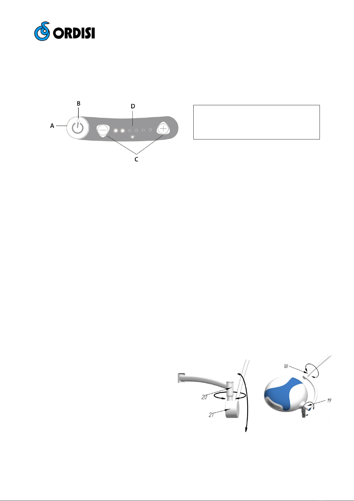
6.2. - AJUSTE DE LOS BRAZOS
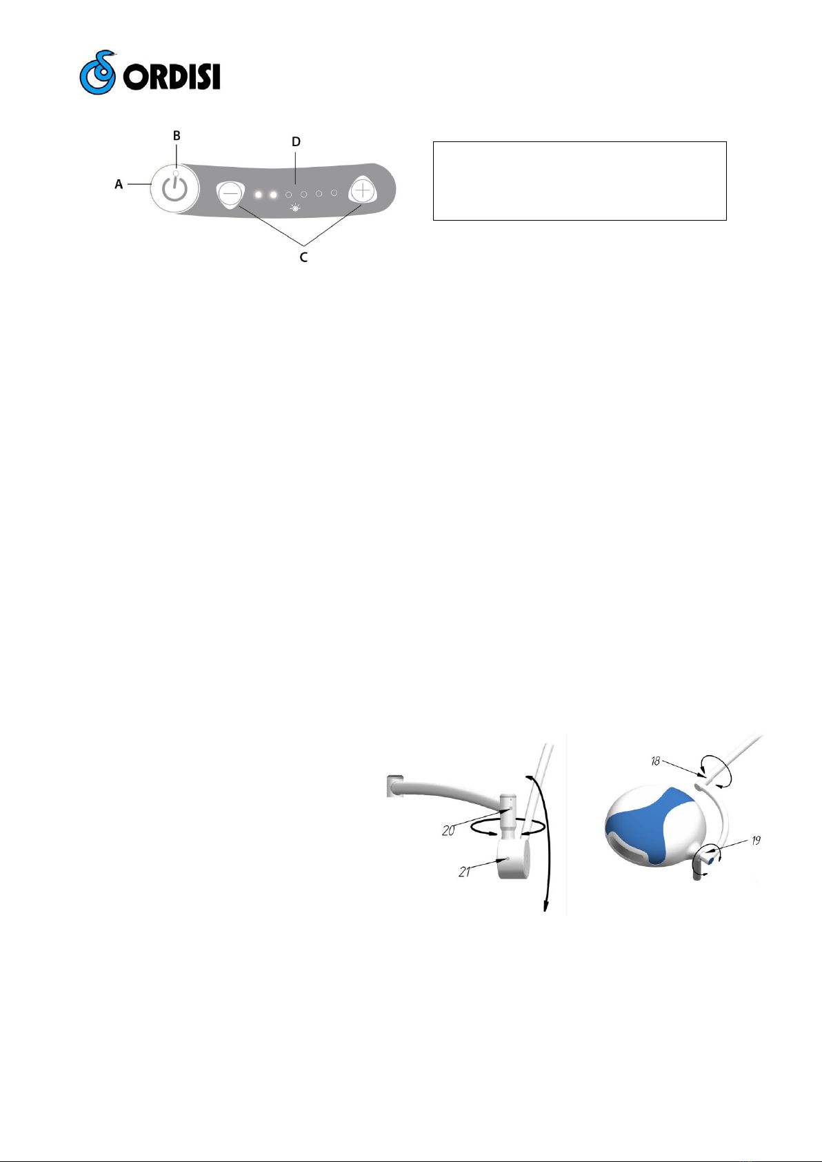
Verificar el ajuste de las rótulas, tanto del brazo
basculante como de la horquilla y la cúpula. En
caso necesario proceder a su ajuste: deben
moverse sin esfuerzo y mantenerse en la posición
deseada. Un exceso de apriete puede producir un
bloqueo del movimiento. Ajustar por medio de los
tornillos nº 18, 19, 20 o 21.
6.3. - CAMBIO DE FUSIBLES
En caso que el interruptor esté en posición "ON" y la lámpara conectada a red, ésta no funcionase, compruebe el estado
del fusible siguiendo estas instrucciones:
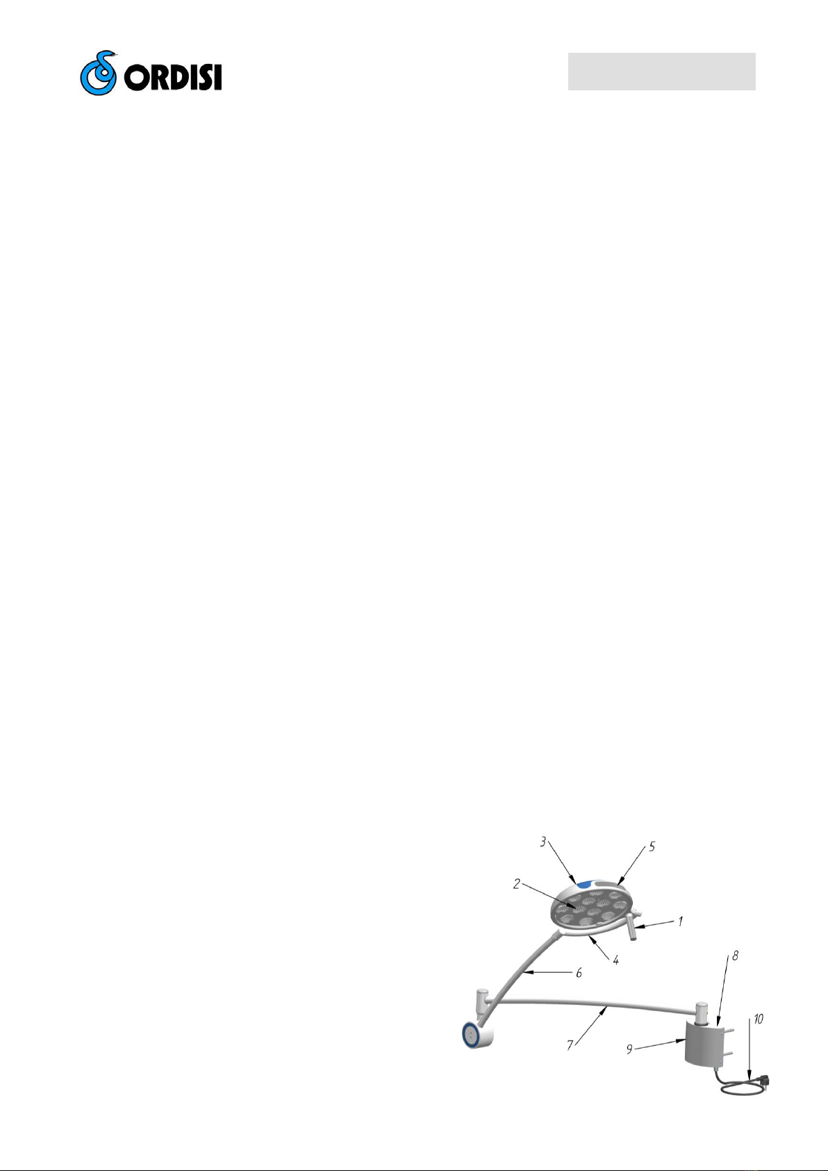
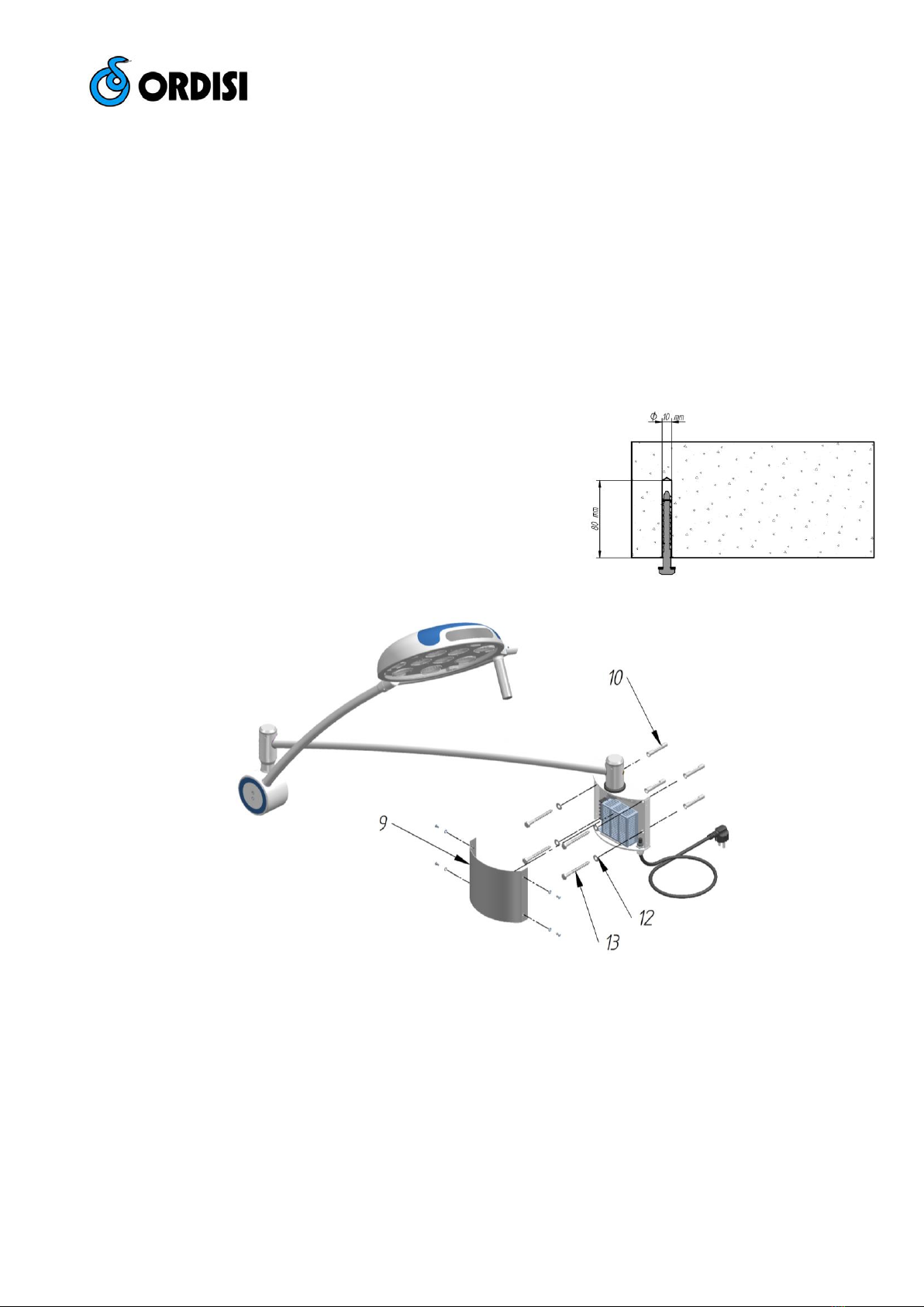
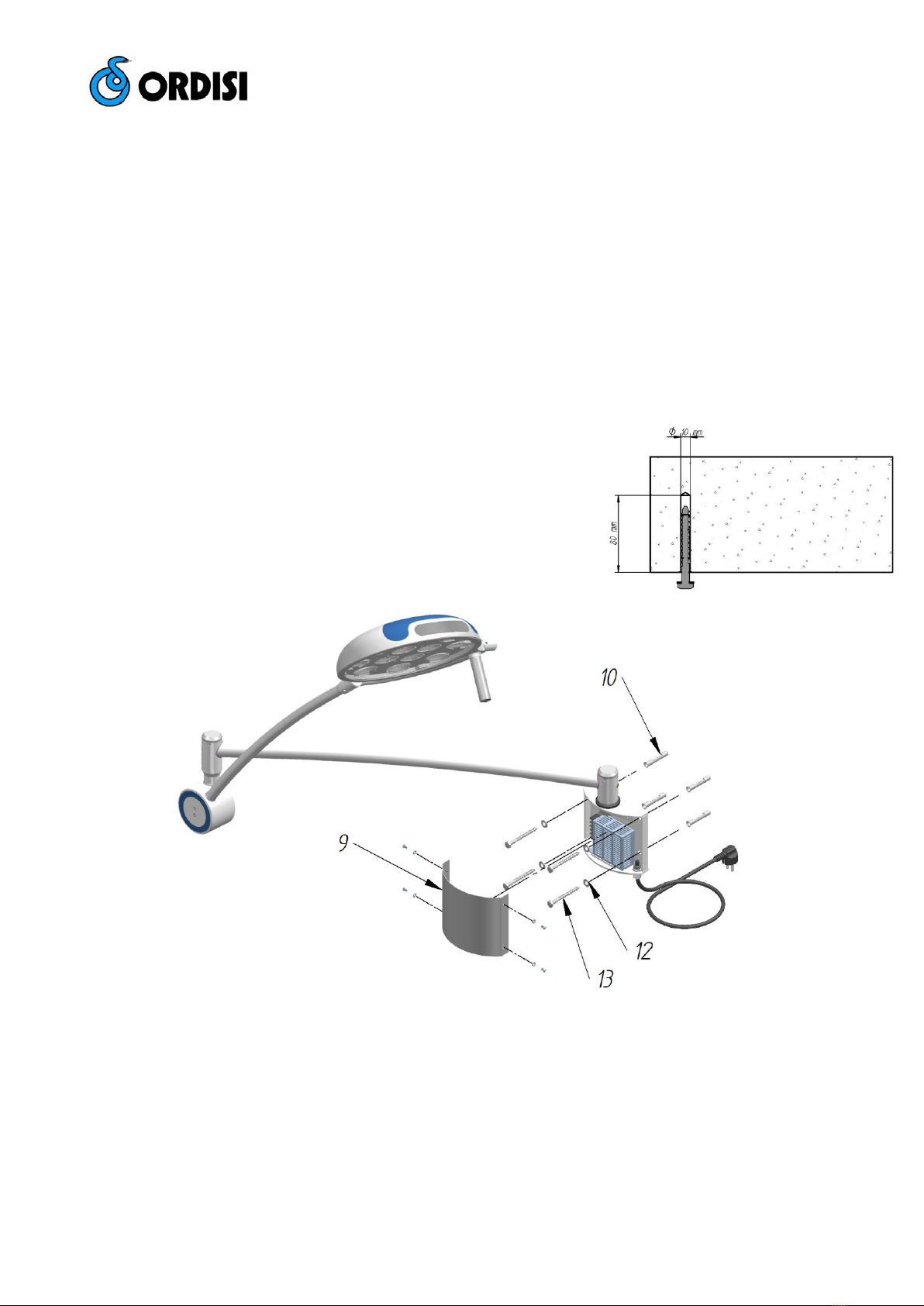
1) Desmontar el embellecedor nº 9.
2) Desenroscar el portafusibles aéreo y reemplazar el fusible. (250VF2A). Comprobar en placa de características.
3) Montar embellecedor.
A – Botón de encendido / apagado
B – Led indicativo encendido / apagado
C – Botones regulación de intensidad lumínica
D – Leds indicativos intensidad lumínica
Fig. 4b – Ajuste de cúpula y horquilla.
Fig. 4a – Ajuste del brazo basculante.