Inledning
Denna anvisning är avsedd att vara ett hjälpmedel vid instal-
lation, användning och underhåll av LDC luftoljekylare.
Förvara anvisningen så att den alltid finns till hands. Ersätt
omedelbart en förlorad anvisning.
Läs igenom anvisningen och varningstexterna noggrant och
se till att förstå innehållet innan du använder luftoljekylaren.
På så sätt får du ut mesta möjliga av din luftoljekylare och
felaktig användning undviks.
Endast för ändamålet utbildad personal får installera,
handha och underhålla luftoljekylaren. ORELL Tec
förbehåller sig rätten till tekniska ändringar.
Avsedd användning LDC luftoljekylare är avsedd för
kylning av olja i hydraulsystem i mobila applikationer.
Garanti och reklamation Vid haveri, kontakta
ORELL Tec ansvarar inte för LDC luftoljekylare efter
egenhändiga reparationer och/eller modifieringar.
Säkerhetsföreskrifter
Installatör och brukare ska känna till, förstå och beakta var-
ningar eller upplysningar, som anges på dekaler, skyltar och
i denna anvisning.
Varningsnivåer och uppmärksamhetstexter...
...gällande personlig säkerhet
Uppmärksamhetstexter, som har med personlig säkerhet att
göra, är klassade i tre nivåer, enligt nedan, beroende på hur
allvarliga följderna av en olycka kan bli.
Fara anger att en olycka kommer att inträffa om
föreskriften inte följs. Olyckan leder till allvarlig
personskada eller möjligen dödsfall.
Varning anger att en olycka kan komma att inträffa
om föreskriften inte följs. Olyckan kan leda till allvar-
lig personskada eller möjligen dödsfall.
Försiktighet anger att en olycka kan komma att
inträffa om föreskriften inte följs. Olyckan kan leda
till personskada.
...gällande övrig säkerhet
Uppmärksamhetstexter som har med övrig säkerhet (egen-
dom, process eller omgivning) och handhavande att göra är
klassade enligt följande:
Viktigt anger att en olycka kan komma att inträffa om
föreskriften inte följs. Olyckan kan leda till skada på egen-
dom, process eller omgivning.
...gällande tilläggsinformation
Tilläggsinformation markeras enligt följande:
Anm! Anger extra information som kan underlätta förståelse
för, eller utförande av, ett visst moment.
Övergripande föreskrifter
Hantering, drift och underhåll
Varning Kläm-/krossrisk. För att undvika personska-
dor vid lyft är det viktigt att använda rätt lyftmetod.
Kontrollera att den lyftanordning och de lyftdon som
används är felfria och godkända för luftoljekylarens vikt.
Försiktighet Risk för personskada. Koppla alltid
bort motorns strömkablar innan underhåll.
Varning Risk för personskada. Se till att systemet är
trycklöst innan hydraulanslutningar och slangar
kopplas bort.
Varning Risk för allvarlig brännskada. Vid drift kan
luftoljekylaren bli mycket varm. Vidrör ej luftoljekyla-
ren förrän den har svalnat.
Försiktighet Klämrisk. Luftoljekylaren kan styras
via en termokontakt. Fläkten startar då automatiskt
vid uppnådd temperatur. Var försiktig vid vistelse nära rote-
rande komponenter.
Försiktighet Risk för förgiftning. Förbrukad olja
skall lämnas på därför avsedd depå för att inte orsa-
ka skada på person, egendom eller miljö.
Viktigt Statisk elektricitet. Fläktar alstrar statisk elektrici-
tet. Undvik känslig utrustning (elektronik m.m.) i systemets
omedelbara närhet.
Anm! Använd hörselskydd vid vistelse under en längre tid i
närheten av ett luftoljekylare i drift.
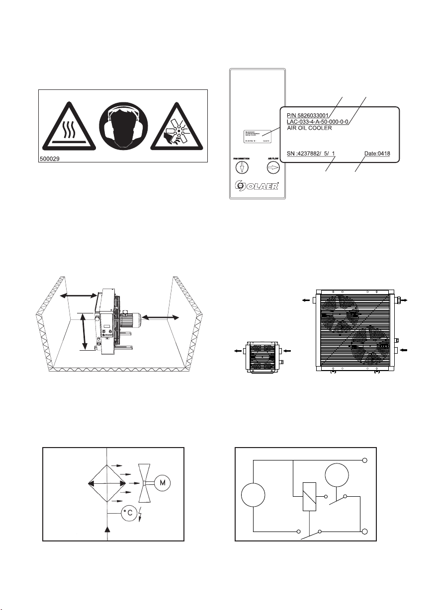
Varningsdekal
Nedanstående dekal är fäst på LDC luftoljekylare vid leverans.
Ersätt alltid en skadad eller saknad varningsdekal.
Varning! eta ytor! Använd hörselskydd! Roterande fläkt!
(Art.nr. 500029 – 70x30 mm alt. Art.nr. 5000291 – 120x50 mm)
Se Bild 1.
Beskrivning
LDC luftoljekylare består i huvudsak av ett kylelement, ett
fläkthus, fläkt med fläktgaller och likströmsmotor.
Likströmsmotor, fläkt och fläktgaller är en och samma enhet.
Fläkten är utrustad med en 12V eller 24V likströmsmotor
som uppfyller direktivet 2004/104/EG avseende anpassning
till 72/245/EEG om radiostörningar; elektromagnetisk kom-
pabilitet hos fordon, (EMC). LDC 023 och LDC 033 är utrus-
tade med två fläktar.
Likströmsmotorn ansluts via kabel försedd med 2-poligt
stifthus. Se motorns märkskylt för aktuell
matarspänning. För lämpligt motorskydd (avsäkring)
kontakta ORELL Tec.
För generella driftsfakta, se Tekniska data.
2 ORELL Tec LDC AIR IL C LER | With DC motor | Installation and servicing manual | Svenska