10
that is ne for now. Then, tighten the three small alignment set
screws equally to secure the secondary mirror in that position.
Adjusting the Secondary Mirror’s Radial Position
Like the axial position, the secondary mirror’s radial position
was set at the factory and will probably not need any adjusting,
or if it does, you’ll typically need to do it only once.
By “radial position” we mean the position of the secondary
mirror along the axis perpendicular to the focuser drawtube.
This position is changed by adjusting two of the spider vane
thumb nuts, as shown in Figure 15. Loosen one thumb nut,
then tighten the opposite one until the secondary mirror is cen-
tered radially in the drawtube. Do not loosen the thumb nuts
too much, to avoid having them completely unthread from the
ends of the spider vanes. Also, when making this adjustment,
be careful not to stress the spider vanes or they could bend.
Adjusting the Secondary Mirror’s Rotational
Position
The secondary mirror should face the focuser squarely. If the
mirror appears to be rotated away from the focuser, the mir-
ror’s rotational position will need to be adjusted. Again, this
adjustment will rarely, if ever, need to be done.
Grip the sides of the secondary mirror holder with your n-
gers. Then, using a large Phillips screwdriver, loosen the cen-
ter screw in the secondary mirror holder about a quarter of a
turn only (counterclockwise). That should be enough to free
up the secondary mirror to rotate slightly in either direction.
Look into the collimation cap and rotate the mirror slightly in
each direction to get an idea of how it affects the view of the
secondary mirror. Now rotate the mirror as needed so that it
precisely faces the focuser. Hold the mirror holder stationary
in that position while turning the center screw clockwise until
it is just tight (do not over-tighten). Sometimes the mirror may
rotate slightly when tightening the screw, so keep at it until the
mirror faces the focuser squarely and is secured in place.
Adjusting the Secondary Mirror’s Tilt
Finally, the tilt of the secondary mirror may occasionally require
adjustment. If the entire primary mirror reection is not visible
in the secondary mirror when using the collimation cap, as in
Figure 11C, you will need to adjust the tilt of the secondary
mirror. Using a small Phillips head screwdriver, rst loosen one
of the three alignment set screws by, say, one full turn, and
then tighten the other two to take up the slack. Do not loosen
the center screw during this process. The goal is to center the
primary mirror reection in the secondary mirror, as in Figure
11D. When it is centered, you’re done adjusting the secondary
mirror. Don’t worry that the reection of the secondary mirror
(the dark circle with the four spider vanes adjoining it) is off-
center, since that adjustment is made when aligning the pri-
mary mirror in the next step.
Aligning the Primary Mirror
The nal collimation adjustment is made to the primary mir-
ror. It will need adjustment if, as in Figure 11D, the second-
ary mirror is centered under the focuser and the reection of
the primary mirror is centered in the secondary mirror, but the
reection of the secondary mirror (dark circle containing the
light reective surface and center black “dot” of the collimation
cap) is off-center.
The tilt of the primary mirror is adjusted with three spring-load-
ed collimation bolts on the rear end of the optical tube (bot-
tom of the primary mirror cell). For the 8" and 10" f/4 models,
the spring-loaded collimation bolts are each tted with a black
knob (Figure 7). The alternating white knobs are attached to
lock bolts, which secure the mirror in place once the correct tilt
has been achieved. For the 6" f/4 model, the three large knobs
are the spring-loaded collimation knobs, while the thinner
knobs (thumbscrew heads) with the screwdriver slot in them
are the lock knobs (Figure 16).
To adjust the primary mirror’s tilt, rst loosen all three lock
knobs by turning them counterclockwise about one turn each.
Now, while looking into the focuser through the collimation
cap, turn one of the collimation knobs a half turn or so in either
direction and see if the secondary mirror reection moves
closer to the center of the primary. That is, does the “dot” of the
collimation cap appear to move closer to the ring on the center
of the primary mirror? If it does, great, keep going until you get
it as close as you can. If it doesn’t, try turning the collimation
knob in the opposite direction. If turning the one knob does not
seem to bring the dot closer to the ring, try using one of the
other collimation knobs. It will take some trial-and-error using
all three collimation knobs to properly align the primary mirror.
Over time you will get the feel for which collimation screws to
turn to move the image in a given direction.
When you have the dot centered as much as possible in the
ring, your primary mirror is collimated. Now lightly tighten the
three lock knobs to secure the primary mirror in that position.
The view through the collimation cap should now resemble
Figure 11E. A simple star test will indicate how well the tele-
scope optics are collimated.
Star-Testing the Telescope
When it is dark, point the telescope at a bright star and accu-
rately center it in the eyepiece’s eld of view. (To achieve focus
with an eyepiece, you will likely have to use the included
35mm extension adapter, as described previously.) Slowly de-
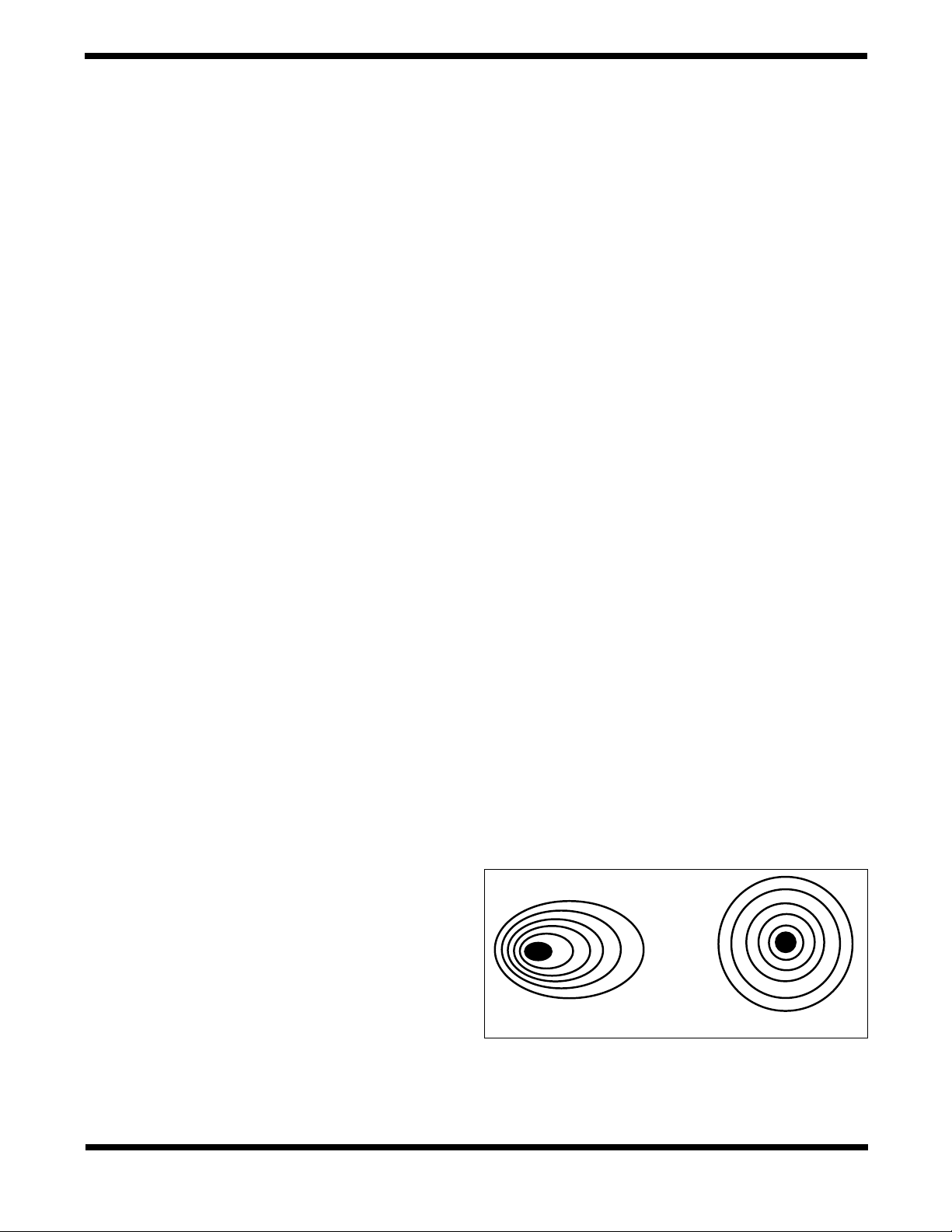
focus the image with the focusing knob. If the telescope is cor-
rectly collimated, the expanding disk should be a perfect circle
(Figure 17). If the image is unsymmetrical, the scope is out
of collimation. The dark shadow cast by the secondary mirror
Figure 17. A star test will determine if the telescope’s optics are
properly collimated. A defocused view of a bright star through the
eyepiece should appear as illustrated on the right if the optics are
perfectly collimated. If the circle is unsymmetrical, as illustrated on
the left, the optics need alignment.
Out of collimation Collimated