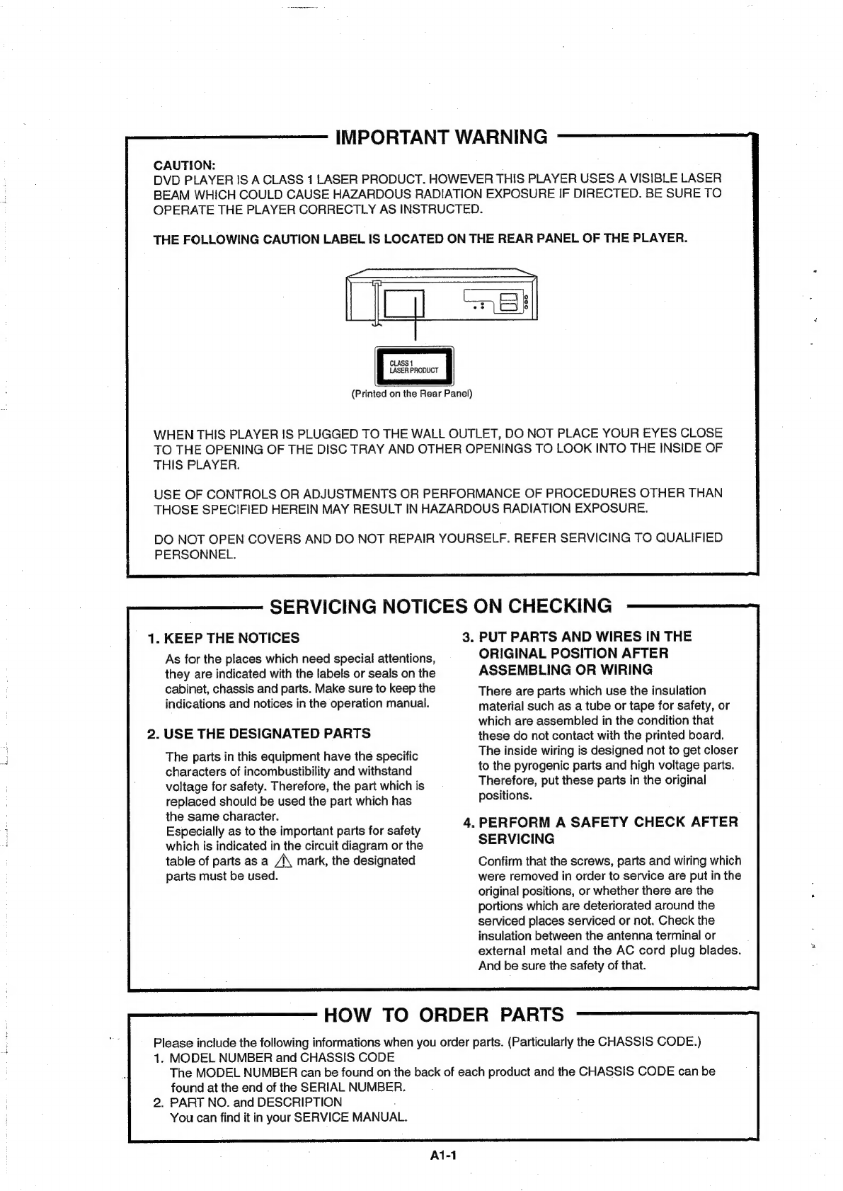
Orion DVD/VR-2961 User manual

SERVICE
MANUAL
Teil
1
ORION
DVD/VR-2961
/
2963
SI
DVD
VIDEO
PLAYER
&
VHS
VIDEO
CASSETTE
RECORDER
OVP
Wee
gcc
Oob=
VIDEO’
DIGITAL
EO
DIGITAL
AUDIO
ORIGINAL
CHASSIS
CODE
A

IMPORTANT
WARNING
CAUTION:
DVD
PLAYER
IS
A
CLASS
1
LASER
PRODUCT.
HOWEVER
THIS
PLAYER
USES
A
VISIBLE
LASER
BEAM
WHICH
COULD
CAUSE
HAZARDOUS
RADIATION
EXPOSURE
IF
DIRECTED.
BE
SURE
TO
OPERATE
THE
PLAYER
CORRECTLY
AS
INSTRUCTED.
THE
FOLLOWING
CAUTION
LABEL
IS
LOCATED
ON
THE
REAR
PANEL
OF
THE
PLAYER.
CLASS
1
LASER
PRODUCT
(Printed
on
the
Rear
Panel)
WHEN
THIS
PLAYER
IS
PLUGGED
TO
THE
WALL
OUTLET,
DO
NOT
PLACE
YOUR
EYES
CLOSE
TO
THE
OPENING
OF
THE
DISC
TRAY
AND
OTHER
OPENINGS
TO
LOOK
INTO
THE
INSIDE
OF
THIS
PLAYER.
USE
OF
CONTROLS
OR
ADJUSTMENTS
OR
PERFORMANCE
OF
PROCEDURES
OTHER
THAN
THOSE
SPECIFIED
HEREIN
MAY
RESULT
IN
HAZARDOUS
RADIATION
EXPOSURE.
DO
NOT
OPEN
COVERS
AND
DO
NOT
REPAIR
YOURSELF.
REFER
SERVICING
TO
QUALIFIED
PERSONNEL.
SERVICING
NOTICES
ON
CHECKING
1.
KEEP
THE
NOTICES
3.
PUT
PARTS
AND
WIRES
IN
THE
As
for
the
places
which
need
special
attentions,
ORIGINAL
POSITION
AFTER
they
are
indicated
with
the
labels
or
seals
on
the
ASSEMBLING
OR
WIRING
cabinet,
chassis
and
parts.
Make
sure
to
keep
the
There
are
parts
which
use
the
insulation
indications
and
notices
in
the
operation
manual.
material
such
as
a
tube
or
tape
for
safety,
or
which
are
assembled
in
the
condition
that
2.
USE
THE
DESIGNATED
PARTS
these
do
not
contact
with
the
printed
board.
The
inside
wiring
is
designed
not
to
get
closer
to
the
pyrogenic
parts
and
high
voltage
parts.
Therefore,
put
these
parts
in
the
original
positions.
The
parts
in
this
equipment
have
the
specific
characters
of
incombustibility
and
withstand
voltage
for
safety.
Therefore,
the
part
which
is
replaced
should
be
used
the
part
which
has
the
same
character.
Especially
as
to
the
important
parts
for
safety
-
PERFORM
A
SAFETY
CHECK
AFTER
which
is
indicated
in
the
circuit
diagram
or
the
SERVICING
table
of
parts
as
a
/\
mark,
the
designated
Confirm
that
the
screws,
parts
and
wiring
which
parts
must
be
used.
were
removed
in
order
to
service
are
put
in
the
original
positions,
or
whether
there
are
the
portions
which
are
deteriorated
around
the
serviced
places
serviced
or
not.
Check
the
insulation
between
the
antenna
terminal
or
external
metal
and
the
AC
cord
plug
blades.
And
be
sure
the
safety
of
that.
HOW
TO
ORDER
PARTS
Please
include
the
following
informations
when
you
order
parts.
(Particularly
the
CHASSIS
CODE.)
1.
MODEL
NUMBER
and
CHASSIS
CODE
The
MODEL
NUMBER
can
be
found
on
the
back
of
each
product
and
the
CHASSIS
CODE
can
be
found
at
the
end
of
the
SERIAL
NUMBER.
2.
PART
NO.
and
DESCRIPTION
You
can
find
it
in
your
SERVICE
MANUAL.
A1-1

CONTENTS
IMPORTANT
WARNING
......ssccssssssssseeensesense
sahara
eaathl
ctsaieeleties
SERVICING
NOTICES
ON
CHECKING.....
HOW
TO
ORDER
PARTS.
«..-ssecssssssssssssssessssssstensseens
TAPE
REMOVAL
METHOD
AT
NO
POWER
SUPPLY
........sssccsssssssssssesssssesssssesnsseeeenseneed
At-2
DISC
REMOVAL
METHOD
AT
NO
POWER
SUPPLY
.....ssccssssssssssssssssessssessssserenseetecnnee
At-2
PARENTAL
CONTROL-RATING
LEVEL
....-scssessessssssssssssestssennsssssttnsrseeeusssssnasionunsseneunsee
At-2
CONTENTS
sescrscsisscccieseitencencs
sons
cracesldatalasieasrainet
la
ee
ei
ia
ter
caster
A2-1
GENERA
SPECIFIGATIONS
s5-.62507.0h-
esata
aca
wecan
tameetn
aiasan
Marien
A3-1~A3-7
DISASSEMBLY
INSTRUCTIONS
1.
REMOVAL
OF
MECHANICAL
PARTS
AND
P.
C.
BOARDS
wu.....:ssssessssseseesesssssssesseneens
B1-1,
B1-2
2x
REMOVAL
OF
VGR:DEGK
PARTS
..cs.2tiasggicnnicenenncnnaiaiaciatatatn
aii
B2-1~B2-6
3.
REMOVAL
AND
INSTALLATION
OF
FLAT
PACKAGE
IC
...ssssssssssssssssesesssesesssssseeseenas
B3-1,
B3-2
KEY
TO
ABBREVIATIONS
cscs
.5:5sjo-4nsereessncoesivirceny
Atte
totes
beveeeaneatuantiiencee
C1-1,
Ct-2
SERVICE
MODE
LIST
ose
cases
anantannnmase
eee
aanennains
2-1
PREVENTIVE
CHECKS
AND
SERVICE
INTERVALS
.........-ccccsssssssssssssesssessssesessseseeesesssenes
C3-1,
C3-2
WHEN
REPLACING
EEPROM
(MEMORY)
IC
.....saccssesssssssssssssssssssesssssssseeusseesnssnesensenesens
C4-4
SERVICING
FIXTURES
AND
TOOLS
.....ccccssssssssssssssssssssseussesinsetseusssstsinssseearetnnssertensee
D1-1
PREPARATION
FOR
SERVICING
....acscsssssessesessessestsssessenseestntesnsenensnsssessuassseensssnnssteseenee
Dt1-1
MECHANICAL
ADJUSTMENTS
f5sscisnccrivicncctesstitenccondictersnatsleesecveaeeluanansonssiteuncarsioutaiy
D2-1~D2-4
ELECTRICAL
ADJUSTMENTS:
sods
scoiiesiisccivieniatea
tata
naan
anenanains
D3-1,
D3-2
BLOCK
DIAGRAMS
DIU
reciente
cieimiec
tae
teres
altaya
Ue
pac
ee
cles
SY
GAUDI
ND
ANA
asin
uclek
adalah
aden
ec
alin
ta
NN
SYTEM
CONTROL/SERVO/TIMEPVOSD
...ssssssessessssssesernseesesnsssssentsnassnsesensstereessessnees
s
REGULATOR
ss
instiete
CAG
aaleicteia
seine
canta
hatin
a
aon
att
toads
OP
ERATIONIDISPLA
Yost
taccatcanatieeat
is
ithnadis
Suan
deatn
leat
Mnannane
TUNER/Hi-Fi/21
PIN/OSD/G-STEREO/NICAM
.....sssssssssssssseesssorsessnonseesnsat
BOWER
icaniaiuntaceisidemncsteoinehtimnettatcat
blu
ianeedemten
ani
tetaniannns
PRINTED
CIRCUIT
BOARDS
VORIDVD
Seccccrsshesinunsant
POWER/OPERATION
SCHEMATIC
DIAGRAMS
VICIATID
OMFIE
RD.
ADAP
sissceatscsecu
ts
cusedecehanasinacioutasbevewiendeerinsbanbeadashacolinbaatttae
aeallenaeae
G-1,
G-2
SVSCON/SEAVO/TIME
RIV
PSS
fcc
seerscestevilacentsartoloastsistaelossagsistes
ccsesenncccutselretgneg
G-3,
G-4
DAP
INTOUNER
35
cct
cat
fc
nc
temic
cancherten
tes
eeecreats
Sate
eaua
aneleatialanda
ttaafanwlaned
G-5,
G-6
PREETI
a
ctes
cise
sactseranssvine
cpcaen
eechee
ete
aaa
ROIs
ton
sal
Saanceae
G-7,
G-8
OPERATION
DISPLAY.
sash
acs5cs.
scste
se
Sianea
a
nti
es
eteaeetalece
ep
retailed
ala
G-9,
G-10
Hi
E
MOD
DIATOM
a2
ciatieeriatueitlanarkoneactietics
adi
tataahena
tite
Sintia
aia,
G-11,
G-12
MPEGIMIOON
sciset
se
cuincts
desea
tates
tseetecineaseece
ee
pe
lid
Rascnrndbega
tacit
tatvccastes
G-13,
G-14
DAES
HOA.
che
chic
eae
bs
haceabas
poche
psn
asec
arbitrate
Manne
esac
cuvette
G-15,
G-16
NG
Paez
actasedicee
ade
cues
steensiugshieee
eae
eee
uan
tcc
atzA
Nii
eal
led
G-17,
G-18
MOTOR
DRIVE
sictarhnd
enya
a
tem
BAA
ihenei
pt
caicnouatidcchiucdda
Coalhantala
hy
G-19,
G-20
LEAD
GHANINEELL
>
steseaces(seresen
sheeheuan
ce
a
calender
noe
G-21,
G-22
ALI
ONIN
O
cess
aisascb
see
vatclstee
ccna
naycscnbc
veoh
oa
naaeig
chickens
da
G-23,
G-34
POWER
sishecshigsescesteite
accede
cbelur
teeta
cea
LS
ate
per
aaah
ante
redciaatia
G-25,
G-26
OR
ERATION
A
scales
sitensastsvboss
ee
saranieter
bs
ierieie
becreteleveaslicputeelet
a
inacgnaliiansia
cuntliatan:
G-27,
G-29
INTERCONNECTION
DIAGRAM
......ccscscssssssssssesecseessssssssssssesstuenssesunsssetnsneseensseensssatnssst
G-29,
G-30
WAWEPORIAS
oi.
ccccsdscissssovceonutasniyenercsrrtia
enstilenso
to
aad
lied
Mich
eataldionacestbadiail
H-1~H-2
MECHANICAL
EXPLODED:
VIEW
accosescscssiessisioti
De
cceirais
sipeatiiuccattinedNantdlaleaitostice
1
GHASSIS
EXPLODED
VIEWS
's.cciir5ssosin
all
rectacatstaies
hurt
ayaseinravn
cher
tastsisiatintediacat
12-1,
12-2
MECHANICAL
REPLACEMENT
PARTS
LIST
«.....ccssssssssesssssssstnsssesesssseeesseetsnsseernsnstenss
Jit
CHASSIS
REPLACEMENT
PARTS
LIST
....scsssscsssssesessssssstssssesssesseusssstennsseeeseenssnaeesni
J2-1
ELECTRICAL
REPLACEMENT
PARTS
LIST
......csscssssssssssssssssssssseseessessnnsseeenteenaneeeenisnt
J3-1~J3-3

TAPE
REMOVAL
METHOD
AT
NO
POWER
SUPPLY
1.
Remove
the
Top
Cabinet,
Front
Cabinet
and
DVD
Block
and
the
Fig.
1
below
can
be
seen.
(Refer
to
item
1
of
the
DISASSEMBLY
INSTRUCTIONS.)
2.
Remove
one
screw
of
the
Loading
Motor
from
the
insert
hole
for
screw
driver
and
remove
the
Loading
Motor.
3.
Rotate
the
Pinch
Roller
Cam
in
the
direction
of
the
arrow
by
hand
to
slacken
the
Video
Tape.
(Refer
to
Fig.
2)
4.
Rotate
the
Clutch-Ass'y
either
of
the
directions
to
wind
the
Video
Tape
in
the
Cassette
Case.
5.
Repeat
the
above
step
3~4.
Then
take
out
the
Video
Cassette
from
the
Deck
Chassis.
Be
careful
not
to
scratch
on
the
tape.
Loading
Motor
Capsian
DD
Unit
tos
Clutch
Assy
CP
Main
Chassis
(Front
Side)
Fig.
2
DISC
REMOVAL
METHOD
AT
NO
POWER
SUPPLY
1.
Remove
the
Top
Cabinet
and
Front
Cabinet.
(Refer
to
item
1
of
the
DISASSEMBLY
INSTRUCTIONS.)
2.
Rotate
the
gear
of
Deck
CD
section
in
the
direction
of
the
arrow
by
hand,
remove
the
disc
from
Deck
CD.
(Refer
to
Fig.
3)
PARENTAL
CONTROL
-
RATING
LEVEL
4-DIGIT
SECURITY
CODE
CANCELLATION
lf
the
stored
4-digit
security
code
in
the
Rating
Level
menu
needs
to
be
cancelled,
please
follow
the
steps
below.
1.Turn
Unit
ON.
2.Press
and
hold
the
'2'
key
on
the
remote
control
unit.
3.
Simultaneously
press
and
hold
the
'STOP'
key
on
the
front
panel.
4.Hold
both
keys
for
more
than
3
seconds.
5.
The
On
Screen
Display
message
‘PASSWORD
CLEAR'
will
appear.
6.
The
4
digit
password
has
now
been
cleared
Ai-2

|
System
G-7
Regulation
Temperature
GENERAL
SPECIFICATIONS
Color
System
PAL
Disc
DVD,
CD-DA,
CD-R/RW,
VIDEO
CD,SVCD
Disc
Diameter
120
mm
,
80
mm
Deck
Disc
Loading
System
Motor
Front
Disc
Loading
3
Motors
Pick
up
{-Lens
2-Beams
System
Playback
time
(Max)
DVD
1-Layer
DVD
2-Layer
cD
VIDEO
CD
135min
(4.7GB)
245min
(8.5GB)
74min
74min
Search
speed
Fwd
Actual
2-20
times
/
4
step
2-45
times
(DVD,
VIDEO
CD)
4-40
times
(CD)
Rev
Actual
2-20
times
/
4
step
2-45
times
(DVD,
VIDEO
CD)
4-40
times
(CD)
Slow
speed
Fwd
Actual
1/7
-1/2
times
System
Actual
VHS
Player
/
Recorder
Video
System
PAL
Hi-Fi
STEREO
Yes
NTSC
PB(PAL60Hz)
Yes
Deck
DECK
Loading
System
Motor
OVD-7
Front
3
Heads
Video
Head
4Head
FM
Audio
Head
2Head
Audio
/Contro!
Mono/Yes
Erase(Full
Track
Erase)
|
Yes
Tape
Rec
PAL
Speed
NTSC
Play
PAL
NTSC
Fast
Forward
/
Rewind
Time
(Approx.)
at
250C
NTSC
or
PAL-M
PAL
or
SECAM
Forward/Reverse
Picture
Search
with
Cassette
SP/LP
FF:1'12"/REW:1'12"
E-180
SP/LP=5x,
7x/
7x,
13x
Frame
Advance
Slow
Speed
Broadcasting
System
Yes
1/5,
1/10,1/30
CCIR
System
BG
Tuner
and
System
Tuner
Receive
CH
Destination
Oscar(W/HYPER)
Tuning
System
F-Synth
input
Impedance
VHF/UHF
75
OHM
CH
Coverage
E2~E4,
X~Z+2,
$1~S10,
E5~E12,811~S41,E21~E69
Picture(FP)
Sound(FS)
FP-FS
Intermediate
Frequency
38.9
MHz
33.4
MHz
5.5
MHz
Auto
Tuning
Method
C.C.1.R
CH
PLAN
Auto
Guide
Ch
Area
Preset
CH
80CH
RF
Converter
Output
Yes
Channel
23~69
CH
Level/Impedance
73
dBu/
75
Ohm
Sound
Selector
Stereo/Dual
TV
Sound
G.ST/NICAM
DUAL
Tuner
Sound
Muting
Power
Source
AC
DC
Power
Consumption
Stand
by
Per
Year
20
W
at
230V
50Hz
5
W
at
230V
50Hz
Power
Fuse
Safety
Protector
Radiation
Operation
A3-1
Storage
-200C
-
600C
Operating
Humidity
Less
than
80%
RH

GENERAL
SPECIFICATIONS
Video
Signal
RGB
Signal
Output
Level
1
V
p-p/75
ohm
(DVD,VCR)
SIN
Ratio
(Weighted)
65
dB(DVD)
63
dBvCrR)
Horizontal
Resolution
Output
Level
500
Lines(DVD)
240
Lines(VCR
atSP)
0.7V
p-p/75
ohm
Audio
Signal
Input
Level
Microphone
Input
Level
Line
“3.8
dBm/
60k
ohm(VGR)
Output
Level
Line
-3.8
dBm/
1k
ohm
(VCR,
0dB=0.775Vims)
-12dB/
1k
ohm
(DVD,
-20dBFs
0dBFs=2.0/rms)
Digital
Output
Level
0.5
V
p-p/
75
ohm(DVD)
S/N
Ratio
at
(Weighted)
90dB(DVb)
42dB(VCR
at
SP)
Harmonic
Distortion
(1KHz)
0.06%
(DVD)
1.5%
(VCRatSP)
Typical
Frequency
Response:
DVD
Mode
at
DVD
DVD
Mode
at
VIDEO
CD
DVD
Mode
at
CD
VCR
Mode
at
SP
VCR
Mode
at
LP
VCR
Mode
at
SLP
4
Hz-
22
KHz
4
Hz-
20
KHz
4
Hz-
20
KHz
4
Hz-
20
KHz
100Hz-
10
KHz
100Hz-
5
KHz
Hi-Fi
Audio
Signal
Dynamic
Range
:
More
than
75dB
Frequency
Response
20Hz
~20kHz
Wow
And
Flutter
:
Less
than
0.01
%Wrms
Channel
Separation
:
More
than
60
dB
Harmonic
Distortion
:
Less
than
A3-2
0.01

{
On
Screen
Display
(DVD)
GENERAL
SPECIFICATIONS
Yes
Menu
Type
Character
Language
Yes
Menu
Yes
Subtitle
Yes
Audio
Yes
Picture
Yes
TV
Screen
Size
Yes
OSD
Display
On/Off
|
Yes
Slide
Show
Interval
Time
JPEG
Interval
Select
Files
DRC
(Dynamic
Range
Control)
dts
Decode
Output
(5.1ch/
2ch)
Surround
On/Off
Center
On/Off
Sub
Woofer
On/Off
Parental
Yes
Password
Lock/Un
Lock
Yes
Rating
Level
Yes
Other
Yes
OSD
Language
(Set
up
Language)
1.
Yes
Output
(RGB/Video)
Yes
Open
Yes
Close
No
disc
Reading
Play
Still/Pause
Stop
Prohibit
Mark
$$
$$$$$_________|_-
Yes
Yes
a
Ss
CI
a
nS
EAT
Yes
Yes
Yes
Yes
Yes
ss
--v-TFTF
I
->
*
eor
S
ee
o
Step
Yes
SKIP
>>]
SKIP
|<<
Random
Repeat
Slow+
##
Slow-
##
Search+
##
Search-
##
i
oooh
Jump
Yes
Yes
Yes
(CD,MP3,
Video
CD,SVCD,WMA,JPEG)
Yes
Yes
No
Yes
Yes
Yes
Resume
Yes
Title
No.
Yes
Chapter
No.
Yes
Track
No.
|
Yes
Time
Yes
Sub
Title
No.
Yes
Angle
No.
Yes
Vocal
On/Off
Yes
Audio
No.
Yes
Audio
Stereo
L/R
Yes
(Video
CD,SVCD)
Zoom
Yes
Marker
No.
Yes
Program
Play
Back
Yes
(CD,MP3,Video
CD,SVCD,WMA,JPEG)
Spatializer
On/Off
No
MP3
Folder
Name
Yes
File
Name
Yes
File
No
Yes
Time
Yes
Track
No
A3-3
Yes

GENERAL
SPECIFICATIONS
Yes
Menu
Type
;
Character
ATS
Timer
Rec
Set
Yes
Auto
Repeat
On/Off
;
Yes
VCR
Set-Up
Yes
NICAM
Auto/Off
Yes
Audio
Mix
On/Off
Yes
Color
System
CH
Set-Up
CH
Tuning
Yes
Auto
Tuning
CH
Mapping
Guide
CH
Set
No
System
Set-Up
Clock
Set
(Calendar
24H)
Language
AV2
DEC/AV
(LINE)
G-CODE(or
SHOWVIEW
or
PLUSCODE)No.
Entry
NICAM
1/2,NICAM
Off,Audio
Output
Stereo,Audio
Output,
Bilingual
Play/Stop/FF/Rew/Rec/OTR/T-Rec/Pause/Eject/Tape
In/Zero
Return
(Symbol
Mark)
Others
CH/AV
(LINE)
Clock
Repeat
Tape
Counter
os
Index
“Tape
Speed
Manual
Tracking
(Bar
Setting)
Hi-Fi
VPS
PDC
TEST
Signal
Calendar
1990/1/1
~
2081/12/31
Timer
Events
8
Program/
1
Month
One
Touch
Recording
Max
Time
6
Hours
OTPB
Valid
Time
Timer
Back-up
(at
Power
Off
Mode)
30
DISPLAY
type
LED
Module
(Green,
"Rec"
&Timer
symbol
=
Clock/Counter,CH,
Timer
Rec,OTR,
Play
Rec,FF(Cue),
Rew(Rev),Stop,ATR,
Eject
VCR
Yes
DVD
Yes
i
CD
Yes
1
Clock
Yes
(24h)
Counter
Yes
(hour:min)
Yes
(hour:min)
Yes
(min:sec)
Counter
Remain
Play
Yes
Stop
Rec
FF
/
Cue
REW
/Review
Pause/Still
OTR
(ITR)
T-Rec
Chapter
TITLE
TRACK
Repeat
Hi-Fi
SP
LP
SLP
CH
RF
Output
CH
Auto
Tuning
Eject
Tape
In
Remocon
Custom
Code
A3-4

G-14
|Remote
Control
GENERAL
SPECIFICATIONS
Unit
RC-Fl
Glow
in
Dark
Remocon
Power
Source
Voltage
(D.C)
UM
size
x
pcs
3V
UM-3
x
2
pcs
Total
Keys
50
Keys
Power
Yes
DISPLAY/CALL
Yes
EJECT
Yes
OPEN/CLOSE
Yes
Yes
Yes
Yes
Yes
Yes
Yes
Yes
Yes
Yes
O/AV
Yes
CH+
Yes
CH-
Yes
SHOWVIEW/PROGRAM
PROGRAM
Yes
TIMER
REC
Yes
REC/OTR
Yes
MARKER/SPEED
Yes
JUMP/ZERO
RETURN
|
Yes
CLOCK
/
COUNTER
COUNTER
RESET
ge
ee
|
TVNVCR
$$
$$$
$f
Yes
Yes
Yes
E.A.M.
REC.END.SEARCH
VCR
DVD
SET
UP/MENU
Yes
—_—
Yes
Yes
DVD
MENU
UP
pS
i
ett
Yes
Yes
DOWN
LEFT
/
TRACKING-
RIGHT
/
TRACKING+
ENTER
/
SELECT
TITLE
RETURN
STOP
PLAY
Yes
Yes
Yes
Yes
Yes
Yes
Yes
Yes
PAUSE
/STILL/STEP
Yes
SKIP-
/
INDEX-
Yes
SKIP+
/
INDEX+
Yes
REW(Review)/SEARCH-
Yes
FF(Cue/SEARCH+
Yes
CANCEL
Yes
REPEAT
A-B
Yes
ZOOM
Yes
SLOW(Forward)
Yes
ANGLE
Yes
PLAY
MODE
Yes
SUBTITLE
Yes
AUDIO
A3-5
Yes

GENERAL
SPECIFICATIONS
G-15
|Features
Auto
Power
Off
Parental
Lock
Progressive
Video
Out
Video
CD
Playback
SVCD
Playback
Overlay
Graphics
And
Text
Command
List
Entry
Point
Jump
MP8
Playback
WMA
Playback
JPEG
Playback
Digital
Out
(Dolby
Digital)
(MPEG)
(PCM)
(DTS)
Down
Mix
Out
(Dolby
Digital)
(DTS)
Spatializer
(N-2-2)
Dynamic
Range
Control
Screen
Saver
Auto
Stop
Features
Auto
Head
Cleaning
(VCR)
Auto
Tracking
Index
Search
HQ
(VHS
Standard
High
Quality)
Auto
Power
On,
Auto
Play,
Auto
Rewind,
Auto
Eject
Auto
Repeat
4
Auto
Power
Off
VIDEO
PLUS+
(SHOWVIEW,
G-CODE)
Auto
Set
Up
(CH
Auto
Set
Up/
Auto
Clock)
ATS
PDC
VPS
|
Remote
Control
Code
1/2/3/4
oy
SQPB
(PAL
SP
Mode
Only)
|
No
wae
CM
Skip(80sec
x
6
Times)
ae
Ss
-
a
Copy
(Disc
to
Tape)
Yes
(by
Conditioning)
Accessories
Owner's
Manual!
Yes
Language
German
w/Guarantee
Card
Yes
Remote
Control
Unit
Yes
Dew
Caution
Sheet
Battery
Yes
UM
size
x
pcs
UM-3
x
2
pes
Tape
Rewinder
Safety
Tip
Toll
Free
Insert
Sheet
|
Quick
Set-Up
Sheet
Yes
aa
Information
Sheet
Yes
75
Ohm
Coaxial
Cable
Yes
(0.9m)
Double
shield
UN
Mixer
DC
Car
Cord
(Center+)
Guarantee
Card
Warning
Sheet
Circuit
Diagram
Antenna
Change
Plug
Service
Facility
List
Important
Safeguard
Dew/AHC
Caution
Sheet
AC
Plug
Adapter
AC
Cord
“AV
Cord
(2Pin-1Pin)
Registration
Card
21pin
Cable
(Double
Shield)
800
ohm
to
75
ohm
Antenna
Adapter
A3-6

GENERAL
SPECIFICATIONS
G-17
[Interface
Front
Power
Play
Eject
(VCR)
Stop
Rec/OTR
Open/Close
(DVD)
CH
+
CH
-
FF/
Search(>>)
Rew/Search(<<)
Still/Pause
Shuttle(Search/REV/FWD)
DVD/VCR
Main
Power
SW
Attenuator
Video/RGB
Selector
RF
Out(Slide
SW)
Main
Power
SW
Volume
Phones
Volume
Mic
Volume
Echo
Volume
Rec/OTR
Terminals
Front
Video
In
RCA
x1(Yellow)
Audio
!n
RCA
x
2(Stereo,
White/Red)
Rear
Indicator
LED
Weight
Video
Output
No
Audio
Output
RCA
x
2(Stereo,
White/Red)
Coaxial
x
1
(Digital
Audio,
DVD
Signal
Only)
Video
Input
Audio
Input
No
Optical
Digital
Audio
Out
(Option)
Euro
Scart
2SCART
Ext
Speaker
VHF/UHF
Antenna
Input/Output
AC
Inlet
Power
Rec
T-Rec
TV/VCR
DVD
VCR
Surround
DIN
Type
No
No
No
.
No
Yes
(GREEN)
Yes
(GREEN)
N
Level
Meter
Net
(Approx.)
ie}
°
Set
Size
Approx.
WxDxH(mm)}
430
x
253
x
99
N
4,0
kg(
8.8
Ibs)
Gross
(Approx.)
Master
Carton
5.0
kg(
11.0
Ibs)
No
Content
---
Sets
Material
sey
Dimensions
WxDxH(mm)
Description
of
Origin
Gift
Box
Yes
Material
Single/Full
Color
W/Color
Photo
Label
No
Dimensions
WxDxH(mm)
497
x
360
x
180
Pulp
Package
No
Design
As
Per
BUYER
's
Description
of
Origin
No
Drop
Test
Natural
Dropping
At
1
Corner
/
3
Edges
/
6
Surfaces
Height
(cm)
80cm
Container
Stuffing
Cabinet
Front
1,985
Sets/40'
container
PCB
Non-Halogen
Demand
Eyelet
Demand
A3-7

DISASSEMBLY
INSTRUCTIONS
1.
REMOVAL
OF
MECHANICAL
PARTS
1-3:
DECK
CD
(Refer
to
Fig.
1-3)
AND
P.C.
BOARDS
1.
Make
the
short
circuit
on
the
position
as
shown
Fig.
1-3
using
a
soldering.
If
you
remove
the
Deck
CD
withno
1-1:
TOP
CABINET
AND
FRONT
CABINET
soldering,
the
Laser
may
be
damaged.
(Refer
to
Fig.
1-1)
2.
Unlock
the
support
©
and
remove
the
Deck
Top
#0
ider
.
Remove
the
5
screws
©.
in
the
direction
of
arrow
(A).
.
Remove
the
Top
Cabinet
in
the
direction
of
arrow
(A).
.
Remove
the
2
screws
@).
.
Disconnect
the
following
connector:
(CP651).
.
Remove
the
2
screws
@).
.
Unlock
the
8
supports
@.
.
Disconnect
the
following
connectors:
(CP2301,
Remove
the
Front
Cabinet
in
the
direction
of
arrow
(B).
CP2302,
CP2601).
.
Remove
the
2
screws
©.
.
Remove
the
Deck
CD
in
the
direction
of
arrow
(B).
.
Remove
the
Operation
PCB
in
the
direction
of
arrow
(C).
.
Remove
the
3
screws
®.
.
Remove
the
Front
Angle
in
the
direction
of
arrow
(C).
op
©
OND
Top
Cabinet
Pick
Up
PCB
Make
the
sort
cuit
using
a
soldering.
1-2:
FLAP
(Refer
to
Fig.
1-2)
1.
Open
Flap
to
90°
and
flex
in
direction
of
arrow
(A),
at
NOTE
the
same
time
slide
in
direction
of
arrow
(B).
When
the
installation
of
the
Deck
CD,
remove
all
the
2.
Then
lift
in
direction
of
arrow
(C).
soldering
on
the
short
circuit
position
after
the
connection
of
Pick
Up
PCB
and
VCR/DVD
PCB
connector.
1-4:
VCR/DVD
PCB
(Refer
to
Fig.
1-4)
1.
Remove
the
screw
@.
2.
Remove
the
2
screws
@).
3.
Disconnect
the
following
connector:
(CP502).
4.
Remove
the
Power
PCB
in
the
direction
of
arrow.
Power
PCB
B1-1

DISASSEMBLY
INSTRUCTIONS
1-5:
VCR
DECK
(Refer
to
Fig.
1-5)
NOTE
Do
not
remove
the
cable
at
the
FE
Head
section.
The
FE
Head
may
be
damaged
if
you
remove
the
cable
by
force.
.
Remove
the
screw
©.
.
Remove
the
FE
Head.
.
Remove
the
3
screws
@.
.
Disconnect
the
following
connectors:
(CP101,
CP102,
and
CP3001).
.
Remove
the
AC
Head
Cover
and
VCR
Deck
in
the
direction
of
arrow.
RON
oa
AC
Head
Cover
1-6:
VCR/DVD
PCB
(Refer
to
Fig.
1-6)
.
Remove
the
screw
©
and
Fiber
Washer.
.
Remove
the
4
screws
@.
.
Remove
the
3-Pin
Shield.
.
Remove
the
VCR/DVD
PCB
in
the
direction
of
arrow.
RON
=
B1-2

DISASSEMBLY
INSTRUCTIONS
2.
REMOVAL
OF
VCR
DECK
PARTS
2-1:
TOP
BRACKET
(Refer
to
Fig.
2-1)
1.
Extend
the
2
supports
©.
2.
Slide
the
2
supports
@
and
remove
the
Top
Bracket.
NOTE
1.
After
the
installation
of
the
Top
Bracket,
bend
the
support
©
so
that
the
Top
Bracket
is
fixed.
Top
Bracket
Main
Chassis
:
a“
:
Main
Chassis
Fig.
2-1
2-2:
CASSETTE
HOLDER
ASS'Y
(Refer
to
Fig.
2-2)
1.
Move
the
Cassette
Holder
Ass'y
to
the
front
side.
2.
Push
the
Locker
R
to
remove
the
Cassette
Side
R.
3.
Remove
the
Cassette
Side
L.
Cassette
Side
R
Main
Chassis
Locker
R
Link
Unit
Cassette
Side
L
Main
Chassis
Fig.
2-2
2-3:
CASSETTE
SIDE
L/R
(Refer
to
Fig.
2-3-A)
1.
Remove
the
Locker
Spring.
2.
Unlock
the
4
supports
@
and
then
remove
the
Cassette
Side
L/R.
3.
Unlock
the
support
@
and
then
remove
the
Locker
R.
Cassette
Side
R
Cassette
Side
L
B2-1
‘NOTE
1.
In
case
of
the
Locker
R
installation,
check
if
the
on
position
of
Fig.2-3-B
are
correctly
locked.
2.
When
you
install
the
Cassette
Side
R,
be
sure
to
Qve
the
Locker
R
after
installing.
Locker
R
Check
if
this
positon
is
locked.
Cassette
Side
R
2-4:
LINK
UNIT
(Refer
to
Fig.
2-4)
1.
Set
the
Link
Unit
to
the
Eject
position.
2.
Unlock
the
support
@.
3.
Remove
the
(A)
side
of
the
Link
Unit
first,
then
remove
the
(B)
side.
Main
Chassis
Link
Unit
Main
Chassis
Fig.
2-4
2-5:
LINK
LEVER/FLAP
LEVER
(Refer
to
Fig.
2-5)
1.
Extend
the
support
@.
2.
Remove
the
Link
Lever.
3.
Remove
the
Flap
Lever.
Link
Lever

DISASSEMBLY
INSTRUCTIONS
2-6:
LOADING
MOTOR/WORM
(Refer
to
Fig.
2-6-A)
1.
Remove
the
screw
©.
2.
Remove
the
Loading
Motor.
3.
Remove
the
Worm.
Loading
Motor
*
Screw
Torque:
3
+
0.5kgf*cm
NOTE
1.
In
case
of
the
Worm
installation,
check
if
the
value
of
the
Fig.
2-6-B
is
correct.
2.
In
case
of
the
Loading
Motor
installation,
hook
the
wire
on
the
Cassette
Opener
as
shown
Fig.
2-6-C.
3.
When
installing
the
wires
between
Capstan
DD
Unit
and
Loading
Motor,
connect
them
correctly
as
shown
Fig.
2-6-D.
19.2+0.1mm
Safety
surface
for
pressing
of
the
insert.
Loading
Motor
Cassette
Opener
Fig.
2-6-C
Loading
Motor
C)
Capstan
DD
Unit
@
B2-2
2-7:
TENSION
ASS'Y
(Refer
to
Fig.
2-7-B)
1.
Turn
the
Pinch
Roller
Cam
clockwise
so
that
the
Tension
Holder
hook
is
set
to
the
position
of
Fig.2-7-A
to
move
the
Tension
Arm
Ass'y.
2.
Remove
the
Tension
Spring.
3.
Unlock
the
2
supports
@
and
remove
the
Tension
Band.
4.
Unlock
the
support
@
and
remove
the
Tension
Am
Ass'y.
5.
Unlock
the
support
@
and
remove
the
Tension
Connect.
6.
Float
the
hook
®
and
turn
it
clockwise
then
remol@
the
Tension
Holder.
Tension
Arm
Ass'y
Tension
Connect
Tension
Spring
Fig.
2-7-B
NOTE
1.
In
case
of
the
Tension
Band
installation,
note
the
direction
of
the
installation.
(Refer
to
Fig.
2-7-C)
2.
In
case
of
the
Tension
Band
installation,
install
correctly
as
Fig.
2-7-D.
3. In
case
of
the
Tension
Connect
installation,
install
as
the
circled
section
of
Fig.
2-7-E.
Tension
Connect
[OK]
Tension
Band
Tension
Connect
[NG]
Tension
Band
Fig.
2-7-D
Tension
Connect
Main
Chassis

DISASSEMBLY
INSTRUCTIONS
-
2-8:
T
BRAKE
ARM/T
BRAKE
BAND
(Refer
to
Fig.
2-8-A)
1.
Remove
the
T
Brake
Spring.
2.
Turn
the
T
Brake
Arm
clockwise
and
bend
the
hook
section
to
remove
it.
3.
Unlock
the
2
supports
@
and
remove
the
T
Brake
Band.
T
Brake
Band
NOTE
1.
In
case
of
the
T
Brake
Band
installation,
install
correctly
as
Fig.
2-8-B.
T
Brake
Arm
[OK]
T
Brake
Band
T
Brake
Arm
Fig.
2-8-B
[NG]
2-9:
S
REEL/T
REEL/IDLER
ARM
ASS'Y/IDLER
GEAR
(Refer
to
Fig.
2-9-A)
4.
Remove
the
S
Reel
and
T
Reel.
2.
Remove
the
2
Polyslider
Washers
©.
3.
Remove
the
Idler
Arm
Ass'y
and
Idler
Gear.
NOTE
1.
Take
care
not
to
damage
the
gears
of
the
S
Reel
and
T
Reel.
2.
The
Polyslider
Washer
may
be
remained
on
the
back
of
the
reel.
3.
Take
care
not
to
damage
the
shaft.
4.
Do
not
touch
the
section
"A"
of
S
Reel
and
T
Reel.
(Use
gloves.)
(Refer
to
Fig.
2-9-A)
Do
not
adhere
the
stains
on
it.
5.
When
you
install
the
reel,
clean
the
shaft
and
grease
it
(FG-84M).
(If
you
do
not
grease,
noise
may
be
heard
in
FF/REW
mode.)
6.
After
installing
the
reel,
adjust
the
height
of
the
reel.
(Refer
to
MECHANICAL
ADJUSTMENT)
B2-3
NOTE
1.
In
case
of
the
S
Reel
and
T
Reel
installation,
check
if
the
correct
parts
are
installed.
(Refer
to
Fig.
2-9-B)
2.
In
case
of
the
Idler
Arm
Ass'y
installation,
install
correctly
as
Fig.
2-9-C.
And
also
set
it
so
that
the
section
'B"
of
Fig.
2-9-A
is
placed
under
the
Main
Chassis
tab.
LES
=
<ZEN
Big
Hole
(S
Reel)
Small
Hole
(T
Reel)
Fig.
2-9-B
[OK]
Outch
Gear
OTTTTTTTIT
cecertrererecenn
(ster
Arm
Assy
[NG]
—
2
Idler
Arm
Ass'y
Clutch
Gear
CMO)
Fig.
2-9-C

DISASSEMBLY
INSTRUCTIONS
2-10:
CASSETTE
OPENER/PINCH
ROLLER
BLOCK/
P5
ARM
ASS'Y
(Refer
to
Fig.
2-10-A)
1.
Unlock
the
support
@
and
remove
the
Cassette
Opener.
2.
Remove
the
Pinch
Roller
Block
and
P5
Arm
Ass'y.
Cassette
Opener
Pinch
Roller
Block
PS
Arm
Ass'y
Main
Chassis
Fig.
2-10-A
NOTE
1.
Do
not
touch
the
Pinch
Roller.
(Use
gloves.)
2.
In
case
of
the
Pinch
Roller
Block
and
the
Pinch
Roller
Cam
installation,
install
correctly
as
Fig.
2-10-B.
Pinch
Roller
Block
Can
be
seen
the
hole
of
the
Pinch
Roller
Cam.
Can
be
seen
the
hole
of
the
Main
Cam.
Fig.
2-10-B
2-11:
A/C
HEAD
(Refer
to
Fig.
2-11-A)
1.
Remove
the
screw
(.
2.
Remove
the
A/C
Head
Base.
3.
Remove
the
3
screws
@.
4.
Remove
the
A/C
Head
and A/C
Head
Spring.
NOTE
1.
Do
not
touch
the
A/C
Head.
(Use
gloves.)
2.
When
you
install
the
A/C
Head
Spring,
install
as
shown
in
Fig.
2-11-B.
3.
When
you
install
the
A/C
Head,
tighten
the
screw
(1)
first,
then
tighten
the
screw
(2),
finally
tighten
the
screw
(3).
A/C
Head
Base
*
Screw
Torque:
5
+
0.5kgf*cm
(Screw
@)
Fig.
2-11-A
Spring
Position
2-12:
FE
HEAD
(RECORDER
ONLY)
(Refer
to
Fig.
2-12)
1.
Remove
the
screw
(@).
2.
Remove
the
FE
Head.
g@
*
Screw
Torque:
5
+
0.5kgfeem
*
The
FE
Head
is
not
installed
on
the
Video
Cassette
Player.
Fig.
2-12
|
2-13:
AHC
ASS'Y/CYLINDER
UNIT
ASS'Y
(Refer
to
Fig.
2-13)
1.
Unlock
the
support
©
and
remove
the
AHC
Ass'y.
2.
Disconnect
the
following
connector:
(CD2001)
3.
Remove
the
3
screws
@.
4.
Remove
the
Cylinder
Unit
Ass'y.
NOTE
1.
When
you
install
the
Cylinder
Unit
Ass'y,
tighten
the
screws
from
(1)
to
(3)
in
order
while
pulling
the
Ass'y
toward
the
left
front
direction.
*
Screw
Torque:
3
+
0.5kgfec

DISASSEMBLY
INSTRUCTIONS
2-14:
CAPSTAN
DD
UNIT
(Refer
to
Fig.
2-14-A)
1.
Remove
the
Capstan
Belt.
2.
Remove
the
3
screws
©.
3.
Remove
the
Capstan
DD
Unit.
Capstan
Beit
Capstan
DD
Unit
¢
Screw
Torque:
4 +
0.S5kgfecm
NOTE
1.
In
case
of
the
Capstan
DD
Unit
installation,
apply
the
silicon
bond
(TSE3843-W)
on
the
position
Fig.
2-14-B
correctly.
(If
no
silicon
bond
applied,
abnormal
noise
will
be
heard
on
the
deck
operation.)
(Refer
to
Fig.
2-14-B,
C)
Applied
position
of
silicon
bond
Be
careful
not
to
apply
the
silicon
bond
to
the
Pinch
Roller.
Fig.
2-14-B
Capstan
DD
Unit
Fig.
2-14-C
2-15:
MAIN
CAM/PINCH
ROLLER
CAM/JOINT
GEAR
(Refer
to
Fig.
2-15-A)
1.
Remove
the
E-Ring
©,
then
remove
the
Main
Can.
2.
Remove
the
E-Ring
®,
then
remove
the
Pinch
Rolear
Cam
and
Joint
Gear.
Pinch
Roller
Cam
Joint
Gear
NOTE
1.
In
case
of
the
Pinch
Roller
Cam
and
Main
Cam
installation,
install
them
as
the
circled
section
of
Fig.
2-
15-B
so
that
the
each
markers
are
met.
(Refer
to
Fig.
2-15-B)
Fig.
2-15-B
2-16:
LOADING
GEAR
S/T
UNIT
(Refer
to
Fig.
2-16-A)
1.
Remove
the
E-Ring
@
and
remove
the
Main
Loading
Gear.
2.
Remove
the
Main
Rod,
Tension
Lever,
Loading
Arm
S
Unit
and
Loading
Arm
T
Unit.
Main
Loading
Gear
Loading
Arm
T
Unit
Fig.
2-16-A

DISASSEMBLY
INSTRUCTIONS
NOTE
4.
When
you
install
the
Loading
Arm
S
Unit,
Loading
Arm
T
Unit
and
Main
Loading
Gear,
align
each
marker.
(Refer
to
Fig.
2-16-B)
Marker
Loading
Arm
S
Unit
Fig.
2-16-B
2-17:
CLUTCH
ASS'Y/RING
SPRING/CLUTCH
LEVER/
CLUTCH
GEAR
(Refer
to
Fig.
2-17-A)
1.
Remove
the
Polyslider
Washer
©.
2.
Remove
the
Clutch
Ass'y
and
Ring
Spring.
3.
Remove
the
Clutch
Lever.
4.
Remove
the
Coupling
Gear,
Coupling
Spring
and
Clutch
Gear.
Clutch
Lever
Fig.
2-17-A
NOTE
1.
In
case
of
the
Clutch
Ass'y
installation,
install
it
with
inserting
the
spring
of
the
Clutch
Ass'y
into
the
dent
of
the
Coupling
Gear.
(Refer
to
Fig.
2-17-B)
Coupling
Gear
Fig.
2-17-B
2-18:
CASSETTE
GUIDE
POST/INCLINED
BASE
9T-
UNIT/P4
CAP/LED
REFLECTOR
(Refer
to
Fig.
2-18-A)
1.
Remove
the
P4
Cap.
2.
Unlock
the
support
©
and
remove
the
Cassette
Guide
Post.
3.
Remove
the
Inclined
Base
S/T
Unit.
4.
Remove
the
screw
@.
5.
Remove
the
LED
Reflector.
Inclined
Base
S
LED
Reflector
*
Screw
Torque:
5
+
0.5kgfecm
Fig.
2-18-A
NOTE
1.
Do
not
touch
the
roller
of
Guide
Roller.
2.
In
case
of
the
P4
Cap
installation,
install
it
with
parallel
for
"A"
and
"B"
of
Fig.
2-18-B.
3.
In
case
of
the
Cassette
Guide
Post
installation,
install
correctly
as
the
circled
section
of
Fig.
2-18-C.
Cassette
Opener
Cassette
Guide
Post

DISASSEMBLY
INSTRUCTIONS
3.
REMOVAL
AND
INSTALLATION
OF
3.
When
IC
starts
moving
back
and
forth
easily
after
desoldering
completely,
pickup
the
corner
of
the
ICUsing
FLAT
PACKAGE
IC
a
tweezers
and
remove
the
IC
by
moving
with
the
|¢
REMOVAL
desoldering
machine.
(Refer
to
Fig.
3-3.)
NOTE
1.
Put
the
Masking
Tape
(cotton
tape)
around
the
Flat
Package
IC
to
protect
other
parts
from
any
damage.
(Refer
to
Fig.
3-1.)
Some
ICs
on
the
PCB
are
affixed
with
glue,
so
be
careful
not
to
break
or
damage
the
foil
of
each
IC
leads
or
solder
lands
under
the
IC
when
removing
it.
NOTE
Masking
is
carried
out
on
all
the
parts
located
within
Blower
typslC
10
mm
distance
from
IC
leads.
desoldering
machine
Masking
Tape
(Cotton
Tape)
Tweezers
2.
Heat
the
IC
leads
using
a
blower
type
IC
desoldering
machine.
(Refer
to
Fig.
3-2.)
4.
Peel
off
the
Masking
Tape.
NOTE
Do
not
add
the
rotating
and
the
back
and
forth
5.
Absorb
the
solder
left
on
the
pattern
using
the
Braided
directions
force
on
the
IC,
until
|C
can
move
back
and
Shield
Wire.
(Refer
to
Fig.
3-4.)
forth
easily
after
desoldering
the
IC
leads
completely.
NOTE
Do
not
move
the
Braided
Shield
Wire
in
the
vertical
direction
towards
the
!C
pattern.
Blower
type
IC
desoldering
machine
Braided
Shield
Wire
Soldering
Iron
IC
pattern
B3-1
This manual suits for next models
1
Table of contents
Other Orion Cassette Player manuals