Orion 52083 User manual

Orion® StarShoot™
Deep Space Monochrome Imager II
#52083
INSTRUCTION MANUAL
Providing Exceptional Consumer Optical Products Since 1975
Customer Support (800) 676-1343
E-mail: [email protected]
Corporate Offices (831) 763-7000
P.O. Box 1815, Santa Cruz, CA 95061
IN 320 Rev. A 10/07

2
Welcome to a new world of adventure. Your new
StarShoot Deep Space Monochrome Imaging camera
II (SSDSMI-2) is capable of capturing detailed images
of astronomical objects; galaxies, star clusters, and
nebula, as well as the planets, Moon, and the Sun (with
optional solar filter). These objects can be imaged to
create spectacular views on your computer (laptop
recommended, see “System Requirements”) which
can be saved for emailing or printing later. You’ll find
that this relatively inexpensive, yet powerful, camera
will enhance your astronomical journeys with your
telescope.
Please read this instruction manual before attempting to use the camera or
install the needed software. For the most detailed information on specific
camera and software functions, consult the Maxim DL Essentials Help menu;
the tutorials found there are especially useful for familiarizing yourself with how
the software and camera are typically used.
Parts List
• StarShoot Deep Space Monochrome Imager II
• USB cable
• 3V Power supply for TEC (requires 2x D-cell batteries, not included)
• CD-ROM
System Requirements (refer to Figure 1)
Telescope
The SSDSMI-2 can be used with virtually any telescope that is compatible with
1.25" format eyepieces. The camera simply is inserted into a focuser in the
same way as a standard eyepiece (Figure 2a).
Important Note: Be sure to always firmly tighten the thumbscrew(s) that
secures the SSDSMI-2 in the telescope focuser, or it could fall out and onto
the ground!
If your telescope is has T-threads for direct camera attachment, a more secure
connection can be made. First, unthread the nosepiece from the SSDSMI-2.
This exposes the camera’s T-threads. Now, simply thread the camera onto your
telescope (Figure 2b).

Securing thumbscrew
3
Figure 1. To use the SSDSMI-2, a telescope, mount, and computer are required.
Figure 2a. The SSDSMI-2 fits into 1.25" focuser, just like a standard 1.25" eyepiece.
Firmly tighten the thumbscrew that secures the SSDSI in the focuser.

Figure 2b. If your telescope has T-threads, remove the nosepiece from the SSDSMI-
2 and thread the camera directly onto the telescope. This provides the most secure
connection.
T-threads
4
In order to reach focus, the telescope must have approximately 0.6" (15mm)
of inward focus travel relative to where a standard eyepiece focuses. If your
telescope does not have enough inward focus travel, you will need to use
and optional 1.25" barlow lens to extend the telescope’s focal plane to the
camera’s imaging plane.
For most types of astro-imaging with the SSDSMI-2 (except planetary imag-
ing), using a telescope with a focal length of under 1000mm is recommended.
Otherwise, the field of view may be too small to capture the entire deep sky
object. To decrease the effective focal length of your telescope, use a focal
reducer lens (available from Orion). If you are imaging planets, however, you
will benefit from using a telescope with a long (over 1000mm) focal length. Or
you can use a barlow lens to extend the effective focal length of your telescope
to increase planetary image scale.
Mount
An equatorial mount with right ascension motor drive is required for deep sky
imaging with the SSDSMI-2. Otherwise, objects will drift in the field of view as
the image is being captured. It is also very important that the mount tracks
very accurately with little periodic error. If not, stars will not appear round in the
final image. Use a sturdy mount that is appropriately sized for the telescope
tube being used. Accurate polar alignment will also be required.

5
Computer
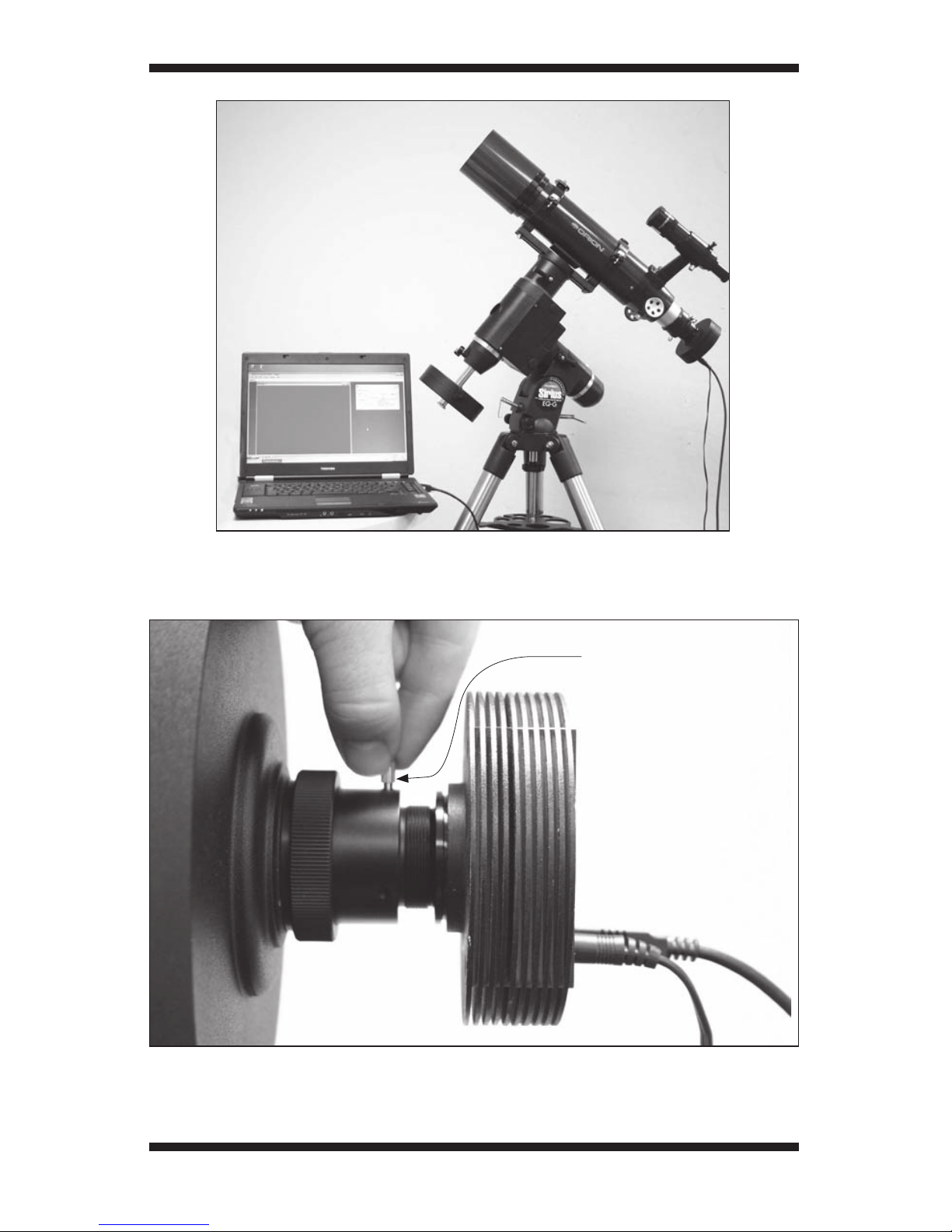
A computer is needed. For astro-imaging in the field at night, a laptop com-
puter is highly recommended. Maxim DL Essentials requires Windows 2000,
Windows XP, or Windows Vista.
The following hardware is also required:
• Processor – Pentium™ or equivalent, or higher
• Recommended minimum memory size is 64 MB.
• Disk Space – 67 MB for program installation, 100 MB swap file recom-
mended
• Video Display – 800 X 600, 16-bit color or higher. 1024x768 or higher is
recommended.
• Mouse
• Internet Explorer 4 or higher required to display on-line help
• USB port (USB 2.0 recommended)
Maxim DL Essentials benefits greatly from increased memory size.
Note: Some computers have USB ports that are known to not meet the USB
specification for the output voltage. These computers may not be able to run
the SSDSMI-2 without the use of an external powered hub. The vast majority of
computers, however, do meet the proper USB specification, and should have no
problems running the SSDSMI-2 off of regular USB power. The SSDSMI-2 itself is
fully USB compliant regarding its power requirements.
Power and the TEC
In order to provide power for the SSDSMI-2’s thermoelectric cooler (TEC), an
external 3VDC power supply is needed. The SSDSMI-2 camera itself runs off
the power supplied by your computer’s USB port; only the TEC requires exter-
nal power. So, if you happen to run out of external 3VDC power in the field, you
can still run the camera without the TEC.
The TEC is like a refrigerator in the camera. When the camera is running, it pro-
duces internal heat, which causes “noise” in images. The TEC counteracts this
by cooling the CCD chip, which reduces thermal noise. This produces better
quality images than similar uncooled cameras can provide. Also, cameras with
simple air-cooling (i.e. with an onboard fan) cannot reduce the internal cam-
era temperature below ambient (outside) temperature, and therefore produce
images that are inherently inferior. The TEC in the SSDSMI-2 will reduce the
temperature of the camera’s interior to approximately 36°F (20° C) below the
ambient outside temperature.
The included 3VDC power supply requires two D-cell batteries (not included).
To install the batteries, open the battery holder by pulling and lifting the tab
on the cover labeled “OPEN”. Then, insert the batteries so the polarity is as
indicated on the interior of the holder.

6
When the 3VDC power supply is plugged into the SSDSMI-2, the TEC is on
(Figure 3). It takes about a minute for the TEC to provide maximum cooling, so
wait a couple of minutes before you begin to capture images. When the power
source is not plugged in, the TEC is off. Remember to unplug the TEC when it
is not in use, or you will drain the power supply. Keeping a spare set of D-cell
batteries in your equipment case is also a good idea!
Software and Driver Installation
Before the camera can be used, software and camera drivers must be installed
onto your computer. Turn on your computer and allow the Windows operating
system to load as normal. Insert the included CD-ROM into your computer’s
CD-ROM drive, and the Launcher will appear (Figure 4). This allows you to
install the Maxim DL Essentials software. After the software is installed, the
drivers will install automatically once the SSDSMI-2 is initially connected to
the computer. Do not connect the camera to your computer before you have
installed the software.
Figure 4. The Launcher provides an
easy menu for software installation.
Figure 3. The 3V power supply (with two D-cell batteries installed) turns the TEC on
when it is plugged into the SSDSMI-2.
3VDC Power supply
Tab
D-cell batteries (2)
USB
cable
Input jack for
TEC power
- +

7
Software Installation
To install Maxim DL Essentials Edition:
1. Insert the CD-ROM into the drive. The Launcher will appear. For Windows
Vista computers, the AutoPlay window will appear. Select Run Launcher.exe,
then the Launcher will appear.
2. Click Install.
3. The InstallShield Wizard will start. Click Next.
4. Read the Maxim DL License Agreement. If you agree with the terms, then
select I accept the terms in this license agreement and click Next.
5. You are now ready to install. Click Install. The installation will proceed.
6. The installation is now complete. Click the Finish button.
You can start Maxim DL Essentials Edition using the desktop icon, or using the
Windows Start menu.
Camera Driver Installation
Now that the software is installed, the camera driver must also be installed.
The system will automatically guide you through driver installation when the
SSDSMI-2 is initially connected to the computer. You must plug-in the camera
before starting Maxim DL Essentials Edition, or the software and computer will
not recognize the camera.
To install the camera driver on a Windows XP computer:
1. Make sure the CD-ROM is in the computer.
2. Connect the Orion StarShoot Deep Space Imager II to a USB port on the
computer with the supplied USB cable. Windows will automatically detect
the camera and start the Found New Hardware Wizard (Figure 5a).
Note: For best results, use a USB 2.0 port. If you only have USB 1.1, the cam-
era will run slower. We highly recommend upgrading to USB 2.0 if you have
USB 1.1. A USB upgrade card can be found from a computer parts supplier.
Note: You do not need to connect the SSDSMI-2 to the external 3VDC power
supply at this time. The external power is for the camera’s thermoelectric
cooler (TEC) only, and normal camera operation does not require it to be on
(i.e. when the TEC is powered it is on, when it is not powered it is off). Use
of the TEC is highly recommended for long exposure astro-imaging, however
(see “Imaging Deep Sky Objects”).
3. Select No, not this time and click Next.
4. Select Install from a list of specific location (Advanced) and click Next.
5. Select Search removable media (floppy, CD-ROM...). Turn off the other
options. Click Next.
6. Windows will start looking for the driver files on the CD-ROM.

8
7. Windows will note that the driver has not passed Windows Logo testing.
This is normal. Click the Continue Anyway button.
8. When the Wizard has completed, click the Finish button. This completes the
driver installation process.
Now, start the Maxim DL Essentials Edition software. The camera will now be
recognized, and the Camera Control Window (Figure 6) will appear. Once the
driver is installed, the computer and software will recognize the SSDSMI-2
whenever it is plugged in.
To install the camera driver on Windows Vista computer:
1. Make sure the CD-ROM is in the computer.
2. Connect the SSDSMI-2 to a USB port on the computer with the supplied
USB cable. Windows will automatically detect the camera and display the
Found New Hardware window (Figure 5b.)
3. Select Locate and install driver software (recommended).
4. In the next window that appears, select Don’t search online.
5. The next window that appears will ask you to “Insert the disc that came
with your StarShoot Camera”. Click Next.
6. A Windows Security window will appear and mention that “Windows can’t
verify the publisher of this driver software”. Choose Install this driver soft-
ware anyway.
Figure 5a. When initially connecting the SSDSMI-2 to a
Windows XP computer, the Found New Hardware Wizard will
appear and guide you through driver installation.

9
7. When the window appears telling you “The software for this device has
been successfully installed”, click Close. This completes the driver instal-
lation process.
Now, start the MaxIm DL Essentials Edition software. The camera will now be
recognized, and the Camera Control Window (Figure 6) will appear. Once the
driver is installed, the computer and software will recognize the SSDSMI-2
whenever it is plugged in.
Note: If your computer (Windows XP or Vista) has multiple USB ports, you will need
to install the driver again if the SSDSMI-2 is connected to a different USB port.
Figure 6.
The Camera
Control Window
automatically
appears when the
SSDSI is connected
to the computer
and the Maxim DL
Essentials program
is started.
Figure 5b. When
initially connecting
the SSDSMI-2 to
a Windows Vista
computer, the Found
New Hardware
window will appear
and guide you through
driver installation.

10
Getting Started During Daylight
We recommend using the SSDSMI-2 for the first time during the day. This
way, you can become familiar with the camera and its functions without hav-
ing to stumble around in the dark. Setup your telescope and mount so the
optical tube is pointing at an object that is at least a couple of hundred feet
away. Insert an eyepiece and focus as you normally would.
Since the SSDSMI-2 camera is so sensitive to light, you will need to “stop
down” your telescope aperture to do any imaging in daylight. This can be done
by creating a simple aperture mask out of a piece of cardboard. The piece of
cardboard should be larger than the telescope’s aperture. Cut a circular hole in
the cardboard approximately 1⁄2" in diameter, and place the cardboard over the
front of the telescope so that it completely covers the aperture except for the
1⁄2" circle. If you are using a refractor telescope, then the hole should be cut so
it is centered on the piece of cardboard. If you are using a reflector that has a
central aperture obstruction, then the hole should be cut off to one side (in order
to bypass the central obstruction). Affix your aperture mask to your telescope
with tape (Figure 7).
Figure 7. Because the SSDSMI-2 is sensitive to light, an aperture mask is needed
on the telescope for any imaging during daylight. For a refractor, the hole should be
centered on the aperture mask. For a reflector, the hole should be off to one side of the
aperture mask.

11
Obtaining First Images
To obtain first images (in daylight) with the SSDSMI-2, follow these step-by-
step instructions:
1. With an eyepiece inserted in the telescope, center and focus an object
that is approximately 1⁄4 mile away. If you cannot focus your telescope this
closely (due to lack of back-focus travel), then you will need to utilize an
optional extension tube (available from Orion).
2. Plug the camera into your computer’s USB port.
3. Open Maxim DL Essentials by clicking on the icon now installed on your
computer’s desktop.
4. Once open, Essentials should connect directly to your camera with the
Camera Control Window.
5. To connect the camera to the telescope, simply replace the telescope’s
eyepiece with the camera. Make sure the securing thumbscrew on the
focuser drawtube is firmly tightened. If your telescope has built-in T-
threads, then remove the eyepiece from the telescope and the nosepiece
from the SSDSMI-2, and thread the camera onto the telescope (see Figures
2a-b).
6. You will now need to refocus the camera for the centered object. Focusing
will be the hardest thing to do in the initial stages. In the Camera Control
Window, set the mode to Light 1x1. Set the Seconds (exposure time) to
.01 to begin with. In the box underneath the Mode box, select Focus. Make
sure the Dark Subtract box is unchecked.
7. Press the Expose button in the Camera Control Window. The camera
will now rapidly take short exposures and display them on the computer
screen. For daytime imaging, open the Screen Stretch Window (in the
View menu), and set the stretch mode to Moon.
8. If the image brightness is too bright for the camera, an all (or mostly) black
screen will result. You will also notice that the Max Pixel (in the lower right
corner of the Camera Control Window, see Figure 6) will be at 65535,
which is the maximum pixel brightness value. Try to get a Max Pixel of
around 50000 to 60000 by increasing or decreasing exposure time (.002
sec is the minimum exposure time). If the (daytime) image is still too bright
to produce an acceptable image on your computer screen, you may need
to stop-down the aperture of your telescope further. Try making another
aperture mask with a diameter of only 1⁄4".
9. Now, turn the telescope’s focus knob so the focuser drawtube moves
slowly inward. The drawtube needs to go approximately 15mm inward from
where the eyepiece focuses (for most eyepieces). Look at the computer
screen and adjust the focus knob accordingly to determine best image
focus.

12
Note: The camera’s field of view is fairly small. It is approximately equivalent to
the field of view through the telescope when looking through a typical (i.e. not
wide-field) 10mm focal length eyepiece. So make sure the object to be imaged
is well centered in the telescope before connecting the SSDSMI-2, otherwise
it may not appear in the field of view of the camera.
10. Once focused, image orientation can be changed by rotating the camera
within the focuser drawtube. Simply loosen the thumbscrew on the draw-
tube and rotate the camera until the desired image orientation is achieved.
Retighten the thumbscrew on the focuser drawtube when done. You may
need to slightly refocus (using the telescope’s focus knob) if the focuser
drawtube has moved a bit inward or outward when the camera was rotated.
11. When the image is focused and the image looks acceptable, press the
Stop button in the Camera Control Window.
12. Beneath the Mode box in the Camera Control Window select Single.
13. Click the Expose button in the Camera Control Window. An image will
appear in a window.
14. You can now save the image for later processing, if you wish. This is done
by selecting Save from the File menu.
You have captured your first image with the SSDSMI-2! This simple method
of imaging is exactly how the camera could be used to capture terrestrial
subjects during daylight hours. Close-up images of birds and other wildlife or
faraway vistas can all be obtained in this way with the SSDSMI-2. Solar images
can also be taken during the day with an optional full-aperture solar filter over
the front of the telescope.
Take some time to use the camera and Maxim DL Essential software during the
day to become familiar and comfortable with their basic operation.
Note: All of the images taken with the SSDSMI-2 are black and white. To obtain
color images with this camera, see “Color Filter Imaging Using the SSDSMI-2
Monochrome”.
Note: In the Camera Control Window, there is a Setup button. Clicking on
this button will allow you to toggle the High Speed Readout Mode on and
off. High Speed Readout Mode should generally be left on unless there is a
specific reason (i.e. your computer system cannot process the higher speed
readout) to turn it off.
Screen Stretch Window
The function of the Screen Stretch Window (Figure 9) is to properly map the
image brightness levels captured by the camera into corresponding image
brightness levels on the computer screen. A typical camera image has each
pixel (light detecting site, over 437,000 pixels form a single SSDSMI-2 image)
represented as a number (from 1 to 65535) depending on brightness. This has
to be mapped into the video monitor’s brightness range (from 1 to 255). It is
important to set the screen stretch appropriately, or a great image may look
terrible!

13
When an image is displayed, you will notice a graph in the Screen Stretch
Window. This is called the “histogram” of the currently displayed image (Figure
10). A histogram is a simple bar graph that shows the range of brightness in
an image. Each bar in the graph represents a level of brightness; the bar to
the far left in the histogram represents the dimmest pixels, and the bar to the
far right is for the brightest pixels. The height of the bar is the total number of
pixels at that brightness level in the image. Every image has a different histo-
gram depending on how much of the image is bright or dark. Directly viewing
the histogram of your image in the Screen Stretch Window provides an easy
interface for making decisions on how the screen stretch should be set.
In Maxim DL Essentials, the two parameters entered in the Screen Stretch
Window are Minimum and Maximum. A pixel that is at the Minimum value
is set to zero (black), and a pixel at the Maximum value is set to 255 (white).
An easy way to adjust the Maximum and Minimum values is to move the
slider arrows located directly under the histogram of the image in the Screen
Figure 9. The settings in the Screen Stretch Window greatly determine how an
image will appear on your computer screen.
Figure 10. A histogram is a visual
representation of the range and levels
of brightness in an image.
Number of pixels
at brightness
level
Range of brightness levels

14
Stretch Window. The red slider arrow corresponds to the Minimum value and
the green arrow corresponds to the Maximum value. Simply left-click and then
drag each arrow to adjust it to the desired level. The best results are obtained
by adjusting the arrows (numbers) until the most pleasing display appears.
There are also seven automatic settings in the Screen Stretch Window.
Typically, Medium will give good results for deep sky objects, so the default
screen stretch setting is Medium.
Instead of using the Screen Stretch Window, it is faster to use the Quick
Stretch facility. This allows you to modify the image appearance instantly with
small up/down and left/right movements of the mouse. To do this, hold down
the Shift key, then left-click and drag the mouse on the image. You’ll find this
feature to be a great convenience when fine adjusting the screen stretch to get
an image to look its best.
The trick with stretching is determining exactly how to stretch the image for
best effect. Often there are several different possibilities for the same image.
Trial-and-error will be the best way to judge what the best screen stretch set-
ting is. Try several different settings until you find one you think looks best.
When the image is subsequently saved, the screen stretch setting information
will be kept when the image is next opened.
Astronomical Imaging
Now that you’re familiar with basic camera and software operation, it’s time to
take the SSDSMI-2 out at night under the stars to capture some astronomical
images. We recommend starting with the Moon, as it is easy to acquire into
the camera’s field of view, and typically does not require stacking of multiple
exposures as planetary and deep sky images do.
Imaging the Moon
Imaging the Moon is much like imaging terrestrial objects during the day. Since
the exposure is very short, it is not critical that the telescope mount be pre-
cisely polar aligned. Best focusing will be achieved by first focusing on a bright
star near the Moon. Start with short exposures of less than 0.1 seconds.
When the moon is past half full, it is hard to get detail due to the tremendous
glare off of the lunar surface. Most detail, even on a sliver of a moon, will be at
the terminator (the tiny thin line between the shadow and light, see Figure 12).
To get more of the moon in the image, a focal reducer will need to be used.
For close-ups of craters use a barlow lens (see “Using Focal Reducers and
Barlow Lenses”).
Imaging Planets
The best planetary images will be obtained by stacking (combining) many
individual images in order to improve image contrast, brightness, and detail.
Because the angular diameter of planets is quite small, you will need to use a

15
Figure 12. The Moon’s surface detail looks the best along the terminator.
barlow lens between the SSDSMI-2 and telescope to extend the effective focal
length of the system and increase image scale (see “Using Focal Reducers and
Barlow Lenses”).
Since you will be taking multiple images over a period of time, it is important
the mount be polar aligned in order to keep the planet within the field of view
of the camera and to prevent image blurring due to poor tracking during each
exposure. To this end, you should also have the right ascension (R.A.) motor
drive engaged. Do not bother trying to obtain a perfect polar alignment, as that
will only be important for taking longer exposure images of deep sky objects;
most planetary exposures will be less than a few seconds.
To take multiple images of a planet for stacking:
1. Acquire the planet into the field of view of your telescope (barlow lens
attached) with an eyepiece and center the planet in the eyepiece’s field of
view. Focus the eyepiece with the telescope’s focuser.
2. Now, remove the eyepiece and replace it with the SSDSMI-2.
3. In the Camera Control Window, set the Mode to Light 1x1. Set Seconds
(exposure time) to 0.5 seconds to begin with. In the box below the Mode
box, select Focus. Click the Expose button.
4. Focus the camera using the telescope’s focus knob. The focus point for the
SSDSMI-2 will be approximately 15mm inwards from the eyepiece’s focus
point. If you are having trouble determining best focus, try focusing on a
bright star near the planet. Use the Planet setting in the Screen Stretch
Window. You can also use the histogram functions for most accurate
focus; this will be explained later (see “Focusing”). Click the Stop button in
the Camera Control Window when camera focus is achieved.

16
5. Now, in the box beneath the Mode box, choose Autosave. Set the number
of images you would like the camera to take under Autosave (start with 10
or so), select the file folder in which you would like to save the images with
Folder, and enter in a Base filename for the captured images. Typically the
name of the object being imaged, such as “Mars1”, will be entered here.
If “Mars1” is the Base filename, and you choose to Autosave five images,
then the images will appear in the selected file folder as “Mars1_0001.fit”,
“Mars1_0002.fit”, “Mars1_0003.fit”, “Mars1_0004.fit”, and “Mars1_0005.
fit”.
6. Click Expose, and the camera will commence capturing and saving the
images.
Now that we have multiple images of the planet, we will combine the images
to form one high-quality resultant image. To do this:
7. Select Open from the File menu. Find the folder you indicated with Folder,
open it, and select all images for stacking using the mouse left-click and
the Shift key. All of the individual images selected will open in Maxim DL
Essentials.
Note: In order to combine images, the images must first be opened in Maxim
DL Essentials.
8. Select Combine from the Process menu. In the pop-up window, you will
see all of the images currently open in Maxim DL Essentials. Choose the
individual images you want to stack and press the >> button, or simply
click Add All. Click the OK button when done.
9. The Combine Images window will appear (Figure 13). For Align Mode,
choose Planetary. In the Output box, select Average.
10. Now, you can see how each individual image looks by using the Next
Image and Previous Image buttons. If you see an image that looks poor,
you can reject it from the stack by clicking the Reject Image button.
Note: At least one image must be used as the reference image for the stacked
images to be overlaid upon. The default uses the first image for the reference
image. If you reject the first image or otherwise want to use another image as
the reference, click the Set As Reference button when the desired reference
image is actively displayed. If the image currently chosen as the reference is
rejected from the stack, and another reference image is not selected, you will
not be able to Overlay All Images.
11. Now, click the Overlay All Images button. All of the selected images will
stack on top of each other to form one resultant image. Click OK.
You have now composed your first planetary image. Use Save under the File
menu to save your image at this time. To make it look its best, you will want
to adjust the Screen Stretch Window to Planet. You may also want to do
some image processing, see the section entitled “Image Processing” for more
information.

Figure 13. The Combine Images window allows “stacking” of individual images into
one high-quality resultant image.
17
Imaging Deep Sky Objects
To capture breathtaking images of deep sky objects, such as galaxies, nebu-
lae, and star clusters, much longer exposures are needed. As with planetary
imaging, you will take several individual images and stack them together to
form one high-quality resultant image. But while planetary images are formed
by stacking many exposures of less than 5 seconds, deep space images will
generally be comprised of individual images of a minute or longer!
Because of this, polar alignment and motor drive tracking must be very
accurate. If not, images will be blurred and stars will not appear round. Also,
because camera noise increases greatly over exposure time (due to internal
heat generation), you will need to suppress the inherent camera noise with
the built-in thermoelectric cooler (TEC). Make sure the 3VDC power supply is
plugged into the SSDSMI-2.
To start:
1. Acquire the deep sky object into the field of view of your eyepiece, and
center it in the eyepiece’s field of view. Focus the eyepiece with the tele-
scope’s focuser. Make sure your equatorial mount is well polar aligned, and
the R.A. motor drive is on and engaged.
2. Remove the eyepiece and replace it with the SSDSMI-2.

18
3. Precisely focus the camera by using the telescope’s focus knob and the
Focus setting in the Camera Control Window. Set the Mode to Light 1x1,
and try an exposure time of a few seconds to start. Use the Medium setting
in the Screen Stretch Window. The focus point for the SSDSMI-2 will be
approximately 15mm inwards from the eyepiece’s focus point. If you are
having trouble determining best focus, try focusing on a bright star near
the deep sky object. If there are no suitably bright stars in the camera’s
field of view, you may need to move the telescope away from the deep sky
object to a bright star, focus on the bright star, and then re-center the deep
sky object in the camera. When you have a good focus, press the Stop
button in the Camera Control Window
4. Now, in the box under the Mode box in the Camera Control Window,
select AutoSave. Set the number of images you would like the camera
to take under Autosave (start with 5 or so), select the file folder in which
you would like to save the images with Folder, and enter in a Base file-
name for the captured images. Typically the name of the object being
imaged, such as “OrionNebula1”, will be entered here. If “OrionNebula1”
is the Base filename, and you choose to Autosave five images, then the
images will appear in the selected file folder as “OrionNebula1_0001.fit”,
“OrionNebula1_0002.fit”, “OrionNebula1_0003.fit”, “OrionNebula1_0004.
fit”, and “OrionNebula1_0005.fit”. Try exposures of 30 Seconds to start.
5. Click Expose, and the camera will commence taking the images.
Note: When the camera is taking long exposure images, it is critically important
not to touch, shake, or otherwise disturb the telescope, or a blurred image will
result. Also, make sure no surrounding light shines into the telescope during
the exposure.
Now that you have multiple images of the deep sky object, we will combine the
images to form one high-quality resultant image. To do this:
6. Select Open from the File menu. Find the folder you indicated with Folder,
open it, and select all images for stacking using the mouse left-click and
the Shift key. All of the individual images selected will open in Maxim DL
Essentials.
Note: In order to combine images, the images must first be opened in Maxim
DL Essentials
7. From the Process menu, select Combine.
8. In the Select Images window, click Add All. Then click OK.
9. The Combine Images window will appear. For Align Mode, choose Manual
1 star – shift only. (If you have field rotation due to a poor polar alignment,
then you can use the Manual 2 stars align mode.) In the Output box, select
Average. Make sure the Use Centroid and Auto Next boxes are checked.

19
Note: In addition to Average mentioned above, 3 other different combining
methods can be chosen: Sum, Median, and Sigma-Clip. To learn more about
these combine methods, see “Image Processing – Combine Tips”.
10. Now, find a well-shaped (circular) star in the first image displayed. Use the
mouse to center the crosshairs on the selected star and left-click.
11. The next image will now be displayed; center the crosshairs on the same
star in this new image, and left-click again. Repeat this for all the open
images; a chime will sound when you have gone through all the open
images. (If you use the Manual 2 stars align mode, then select another
alignment star in the first image displayed after you hear the chime.)
12. If you find an image that looks poor, you can reject it by clicking the Reject
Image button. Use the Next Image (and/or Previous Image) button to con-
tinue going through the open images after an image is rejected.
Note: At least one image must be used as the reference image for the stacked
images to be overlaid upon. The default uses the first image for the reference
image. If you reject the first image or otherwise want to use another image as
the reference, click the Set As Reference button. If the image currently chosen
as the reference is rejected from the stack, you will not be able to Overlay All
Images.
13. Now, click the Overlay All Images button. All of the selected images will
stack on top of each other to form one resultant image. Click OK.
Adjust the Screen Stretch Window to Medium (or otherwise manually adjust
for best image appearance), and use Save under the File menu to save your
image. You can now perform any wanted imaging processing (see “Image
Processing”). To get the very best images, however, you should subtract “dark
frames” from images prior to stacking with the Combine function.
Dark Frames
To completely eliminate any remaining camera noise, you can take several
“dark frames”, average them, and subtract them from images before stacking.
A dark frame is an image taken with no external light coming into the camera.
What results is an image of the camera’s remaining background noise only.
When a dark frame containing the camera’s noise pattern is subtracted from
images (prior to combining them), the noise is essentially eliminated. The dark
frames can be taken before or after the “light” images are acquired, but if they
are taken beforehand, the dark frame subtraction process can be automated.
Note: To most effectively use dark frames to subtract noise out of resultant
SSDSMI-2 images, it is important to take dark frames close to the actual time
of taking the “light” images. This is because temperature changes will cause
the noise pattern in the SSDSMI-2 to change over time. So, it is best to take
some dark frames immediately before or after the “light” images are taken.

20
To take dark frames for subtraction from “light” images:
1. In the Camera Control Window, set the Mode to Dark 1x1.
2. Set the exposure time to whatever you set it to (or will set it to) for taking
actual (“light”) images.
Note: When taking dark frames, do not change any of the settings in the Setup
button from what they were (or will be) when “light” images are taken.
3. In the box beneath the Mode box, choose Autosave. Now set the number of
dark frames you would like the camera to take under Autosave (3 to 10 will
generally suffice, as these will be averaged together), select the file folder
in which you would like to save the dark frames with Folder, and enter in a
Base filename for the captured dark frames. Typically the name of the object
being imaged with the word “dark” added, such as “OrionNebula1dark”,
will be entered here. If “OrionNebula1dark” is the Base filename, and
you choose to Autosave five images, then the images will appear in the
selected file folder as “OrionNebula1dark_0001.fit”, “OrionNebula1dark_
0002.fit”, “OrionNebula1dark_0003.fit”, “OrionNebula1dark_0004.fit”, and
“OrionNebula1dark_0005.fit”. Using the word “dark” in the Base filename
will help you distinguish between light and dark frames when combining
later.
4. Click Expose, and Maxim DL Essentials will indicate the camera needs to
be covered to take a dark frame. Cover the front of the lens you are imaging
through, and then click OK. The camera will commence taking and saving
the dark frames.
Now that you have acquired several dark frames, combine them into a single
averaged dark frame for subtraction from “light” images:
5. In the Process menu, select Setup Dark Subtract.
6. In the window that pops-up, click Remove All if any filenames appear in
the window.
7. Click Add, and select the file folder location for the dark frames taken.
Select the dark frames and click Open.
8. The selected dark frames will now appear in the pop-up window. Click OK.
The dark frames have now been averaged and stored into memory.
You are now ready to subtract the averaged dark frame from “light” images.
This should be done to individual light images BEFORE combining them
together. There are two ways to do this. If you take dark frames first, before
taking light images (using Light 1x1), then you can automatically subtract the
averaged dark frame from each individual light image as it is captured. If you
take dark frames after you have already taken the light images (using Light
1x1), then you can subtract the averaged dark frame from each individual
image before you combine them into a single, final resultant image.
This manual suits for next models
1
Table of contents
Other Orion Digital Imaging Accessories manuals