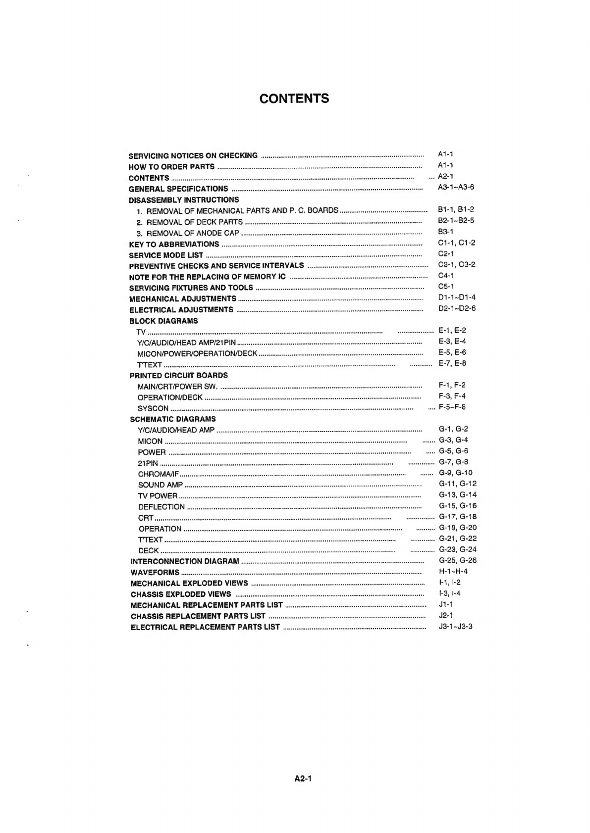
CONTENTS
SERVICING
NOTICES
ON
CHECKING
veccsseteeesee
AST
HOW
TO
ORDER
PARTS.
0...
esecsssssssesseeeesesenessscsnesneasrevenenecesssenenssecssecennecersnenesseseeans
Re
Ai-1
CONTENTS
a
.
A2-1
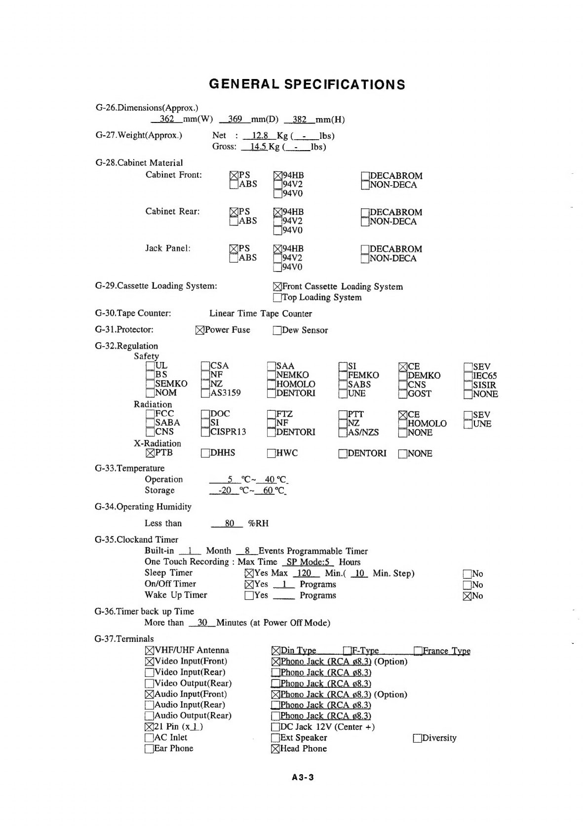
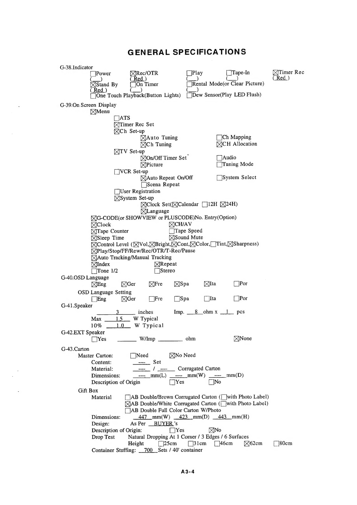
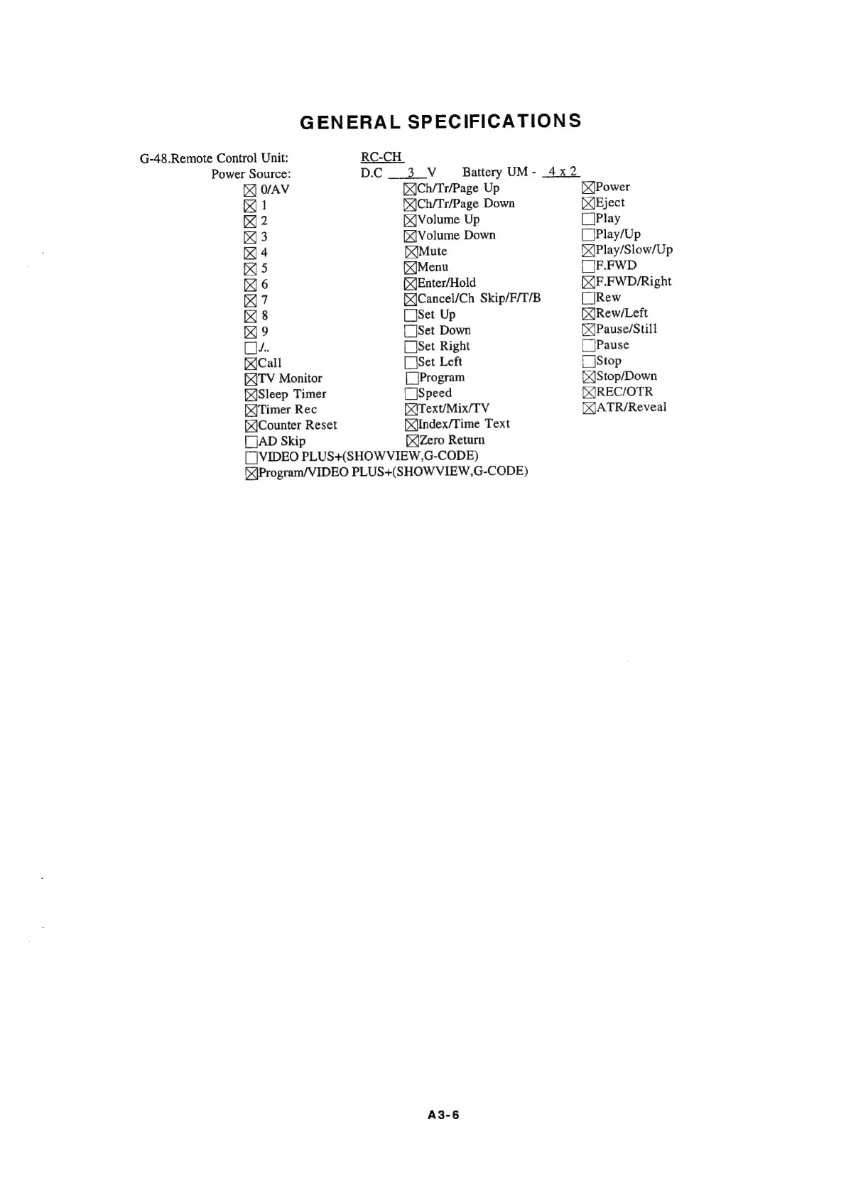
GENERAL
SPECIFICATIONS.
ou...
cscssssescsesssssesssssnecessesecnenensasvensentsssassceneracersnesenennsensneoess
A3-1~A3-6
DISASSEMBLY
INSTRUCTIONS
1.
REMOVAL
OF
MECHANICAL
PARTS
AND
P.
C.
BOARDS........ecsseseseerseseserensensssceneennees
Bi-1,
B1-2
2.
REMOVAL
OF
DECK
PARTS.
......cssssssssessssssresesesnesnssenracscensssscensnsrssecacasscseavavaneaescsseateeees
B2-1~B2-5
3.
REMOVAL
OF
ANODE
CAP
qu...
csssssssescsssseessesenenetensssnescesasseneneaeanansescesseneseneeaeeenesenenanans
B3-1
KEY
TO
ABBREVIATIONS
Qo...
cesscccessessssessssersssesrenseecsesnesessensuseesesenanenssusnssesareenessssseanesesscersees
C1-1,
C1-2
SERVICE
MODE
LIST
...........scecessesssesenscnescneeeenenserenee
‘
C2-4
PREVENTIVE
CHECKS
AND
SERVICE
INTERVALS
..................
wwe
63-1,
C3-2
NOTE
FOR
THE
REPLACING
OF
MEMORY
IC
.........eseeseeeeees
wee
C464
SERVICING
FIXTURES
AND
TOOLS.
...........csessssseeeterteseeseesesseeeescesennsessessenseneeseeeseets
.
C51
MECHANICAL
ADJUSTMENTS
...........ccccsesssssessesensssenensecssacensaessanenseneansscisseesnneneaes
i
D1-1~D1-4
ELECTRICAL
ADJUSTMENTS.
ou...
sssescesessssereecsesesenecsssssssesenensssnsereosoesarssenseesesisanenenseseesess
D2-1~D2-6
BLOCK
DIAGRAMS
To
rcssasecessbcutesSusout
eleveevssonsduosedickeacbiedicsencvdstatesdussecesedvaressussveasessavtoccdeceiaveneséeypaeasatands
|
|
gesndscaceedeenssee
E-1,
£-2
YICIAUDIO/HEAD
AMP/21PIN
uu...
sscssssesesssssesessrsnsssstsessenseeeeeenssssersesecnsasasanseneasceresscesseneaseseesene
E-3,
E-4
MICON/POWER/OPERATION/DECK
......sescssssssesscerssssesssseseesacsnenssnsssurnssneassesnscaenannrarssssecusenees
E-5,
E-6
TTEXT
u.cecessssessssssesessecsssesessessssesssnssssassevesesessencssscescsnsnsnnenennsgeassaseasdensvescansanssesssusossansets
senenenee
E-7,
E-8
PRINTED
CIRCUIT
BOARDS
MAIN/CRT/POWER
SW,
uu...
eesssssssssstssssrtsnscsessnseeessesarsesseasasenevenennesenecusnecnsnsseseananensaeransneesenense®
F-1,
F-2
OPERATION/DECK
.
a
F-3,
F-4
SYSCON
onvcscccsssssssesessssssecsvsscecsesscsscsesseeseensesseeesncsrsneessaceussessssenenseaesessegeenanseaenentananenenevenu
assert
wee
F-5~F-8
SCHEMATIC
DIAGRAMS
Y/CIAUDIO/HEAD
AMP
G-1,
G-2
MICO
.....c.ssescssccsossessscsscsesscessosscsennessusorsserssacoussscavensaneansnesetecosscanesescensensas
‘
G-3,
G-4
POWER
uu.
eeeesscssesessccscsessssssecssscsssoeensenessesnsossesssnenesnsenenssscansncosnseseeesesoasegusanensssecocssaranesenennenas
G-5,
G-6
QIPIN
vcsscesessssesscesseesesscsececsssoesssssnsarsenssuceesecaeseseseseessesnenseeracarsesesanseennsesssnesanarsnesensrseter
sraeanrareees
G-7,
G-8
CHROMA
SIF
........sscscscessssecsesesesessecsssvsessssssnsssessnssanesssonsneassesersnsecessesesecnesassnseensseazenanunanseneos
—
avenene
G-9,
G-10
SOUND
AMP.
......sssessssssessssssssesersssessssssessossssonessenvenssssansssnressacneaccanonassacsasenssesennonusoseraseuevseasorsee
G-11,
G-12
TV
POWER
...sscccsssesscessscesesnsssssssssssesacsnsevescersucesssnsesneassosnenecseaavencaecesesasnvsasaceuscecessssasnerrenstsenss
G-13,
G-14
DEFLECTION
......cssssessccsssssrssssessssrssesenessesesessesenssensusacestssserseneensscasoneasaveassscavansecsansustsesaneeanenegss
G-15,
G-16
CRT
cnesscsscssssscsesscssesscvsscssssososscssssssssnssacanssuesusnsorassesnsrauseescnsevensarsusssscucacsseseansonsesarasssess
—
sauseeananenaes
G-17,
G-18
OPERATION
......csssessssssessseesssssccsssssssnsesssessesessecessnesasssescnesersenerssecseansessnsneassassearanennescensns
—
aanseeseas
G-19,
G-20
TTS
TEXT:
Sissscsvecettcsan
ence
vssuectescvesvsssussosascnssesteveshscccsansssscuctecsessst
evsbucaebncoiveedisedisosesdvacuansdegesss
©
“ssetyZeedistee
G-21,
G-22
DEGK
sesocicdessctiicsasticesieteoscdsenccnsdensschssssdeinsebelasiaacesosdsiiecosobenstedoisosscosteobsbendeesdestnaielaescen:
©
oapbéterteedt
G-23,
G-24
INTERCONNECTION
DIAGRAN
.
ae
G-25,
G-26
WAVEFORMS
......
cc
cssessssessssesesessnsscsersseersesesesesennesssanensernasnenerensrennies
H-1~H-4
MECHANICAL
EXPLODED
VIEWS.
.........::scessssssssesseneesesseenseneneeses
a
1,
1-2
CHASSIS
EXPLODED
VIEWS.
.......usesssssesssesesserensenessenesssecaseenesnsssneeussssesensnenensnsoesegnenseneersaseats
1-3,
I-4
MECHANICAL
REPLACEMENT
PARTS
LIST
............ecccsecssssssesesssnsneesenesssensnenensssanseeerseencarenees
Jt-4
CHASSIS
REPLACEMENT
PARTS
LIST
...........:sscsssssssssssenscessensssenenssssereneesessnansscessnessenssonecsoes
J2-1
ELECTRICAL
REPLACEMENT
PARTS
LIST
............csssssssssseseessssesrenseseensersseenenenensensnenesecenenes
J3-1~J3-3
A2-1