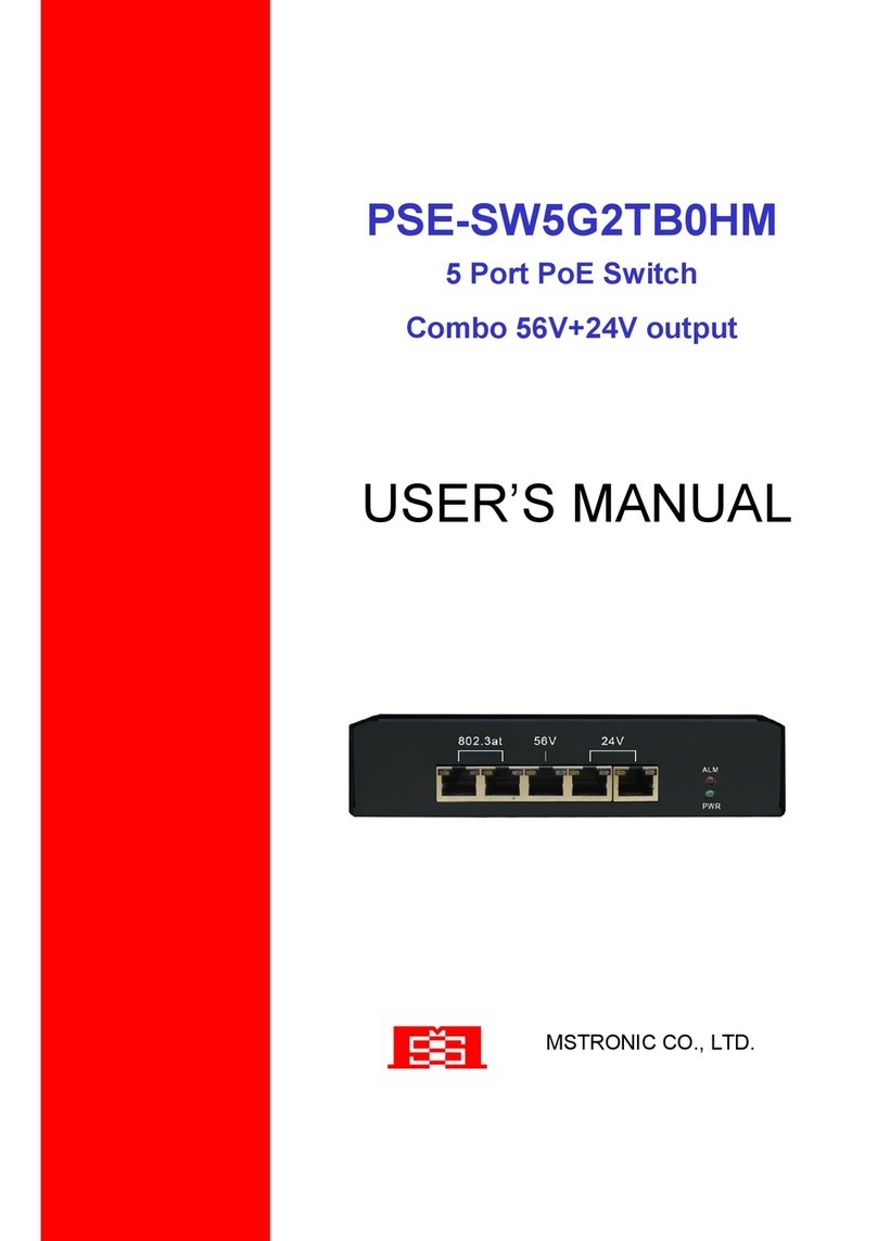
OSD Audio 2600P series User manual

OPERATOR MANUAL
OSD2600P SERIES
MANAGED
ETHERNET SWITCH


OPTICAL SYSTEMS DESIGN
DOC ID: 10112303
OSD2600 OPERATOR MANUAL
PAGE 3
INDEX 1
1
QUICK START GUIDE ............................................................................................................ 5
1.1
P
HYSICAL
D
ESCRIPTION
............................................................................................................ 5
1.2
F
UNCTIONAL
D
ESCRIPTION
....................................................................................................... 6
1.3
C
ONSOLE
C
ONFIGURATION
....................................................................................................... 7
1.3.1
C
ONNECT
T
O
T
HE
S
WITCH
C
ONSOLE
.................................................................................... 7
1.3.2
C
ONFIGURATION
S
ETTINGS
O
F
T
HE
T
ERMINAL
-E
MULATION
P
ROGRAM
............................... 7
1.4
W
EB
C
ONFIGURATION
............................................................................................................... 8
2
TECHNICAL SUMMARY...................................................................................................... 10
2.1
B
RIEF
D
ESCRIPTION
................................................................................................................ 10
2.1.1
P
REFACE
.............................................................................................................................. 10
2.1.2
O
VERVIEW
.......................................................................................................................... 10
2.1.3
A
PPLICATIONS
..................................................................................................................... 10
2.1.4
F
EATURES
A
ND
B
ENEFITS
................................................................................................... 10
2.2
T
YPICAL
C
ONFIGURATION
....................................................................................................... 11
2.3
T
ECHNICAL
S
PECIFICATIONS
................................................................................................... 12
2.4
OSD2600P
F
RONT
A
ND
R
EAR
P
ANELS
................................................................................... 13
2.4.1
OSD2600P
D
IMENSIONS
..................................................................................................... 13
3
INSTALLATION AND OPERATION................................................................................... 14
3.1
I
NTRODUCTION
........................................................................................................................ 14
3.2
I
NSTALLATION
......................................................................................................................... 14
3.2.1
W
ARNING
A
ND
P
RECAUTIONS
............................................................................................. 14
3.2.2
P
OWER
S
UPPLY
C
ONNECTIONS
............................................................................................ 15
3.2.3
LED
I
NDICATORS
................................................................................................................ 15
3.2.4
W
EB
-B
ASED
B
ROWSER
I
NTERFACE
..................................................................................... 15
3.2.5
A
DMINISTRATION
C
ONSOLE
V
IA
RS-232
S
ERIAL
P
ORT
(CLI) ............................................ 15
3.2.6
E
XTERNAL
SNMP-B
ASED
N
ETWORK
M
ANAGEMENT
A
PPLICATION
................................... 15
3.2.7
A
LARMS
F
OR
P
OWER
F
AILURE
............................................................................................ 16
3.3
OSD2600P
O
PERATION
........................................................................................................... 17
3.3.1
C
ABLE
C
ONNECTIONS
......................................................................................................... 17
4
SWITCH MANAGEMENT..................................................................................................... 18
4.1
M
ANAGEMENT
A
CCESS
O
VERVIEW
......................................................................................... 18
4.2
A
DMINISTRATION
C
ONSOLE
(CLI) .......................................................................................... 18
4.2.1
D
IRECT
A
CCESS
................................................................................................................... 18
4.3
W
EB
M
ANAGEMENT
................................................................................................................ 19
4.4
SNMP-B
ASED
N
ETWORK
M
ANAGEMENT
............................................................................... 19
4.5
P
ROTOCOLS
............................................................................................................................. 19
4.6
M
ANAGEMENT
A
RCHITECTURE
............................................................................................... 19
5
SNMP & RMON MANAGEMENT........................................................................................ 20
5.1
O
VERVIEW
.............................................................................................................................. 20
5.2
SNMP
A
GENT
A
ND
MIB-2
(RFC
1213).................................................................................. 20
5.3
RMON
MIB
(RFC
2819)
A
ND
B
RIDGE
MIB
(RFC
1493)....................................................... 21
5.3.1
RMON
G
ROUPS
S
UPPORTED
............................................................................................... 21
5.3.2
B
RIDGE
G
ROUPS
S
UPPORTED
.............................................................................................. 21
6
WEB-BASED BROWSER MANAGEMENT........................................................................ 22
6.1
L
OGGING
O
N
T
O
T
HE
S
WITCH
................................................................................................. 22
6.2
U
NDERSTANDING
T
HE
B
ROWSER
I
NTERFACE
.......................................................................... 23
6.3
S
YSTEM
................................................................................................................................... 24
6.4
P
ORT
....................................................................................................................................... 34
6.5
S
WITCHING
.............................................................................................................................. 39

OPTICAL SYSTEMS DESIGN
DOC ID: 10112303
OSD2600 OPERATOR MANUAL
PAGE 4
6.6
T
RUNCKING
............................................................................................................................. 44
6.7
STP
/
R
ING
.............................................................................................................................. 45
6.8
VLAN ..................................................................................................................................... 53
6.9
Q
O
S......................................................................................................................................... 58
6.10
SNMP ..................................................................................................................................... 61
6.11
802.1
X
..................................................................................................................................... 66
6.12
O
THER
P
ROTOCOLS
................................................................................................................. 70
7
COMMAND LINE CONSOLE MANAGEMENT................................................................ 75
7.1
A
DMINISTRATION
C
ONSOLE
.................................................................................................... 75
7.1.1
E
XEC
M
ODE
(V
IEW
M
ODE
) ................................................................................................. 76
7.1.2
P
RIVELEDGED
E
XEC
M
ODE
(E
NABLE
M
ODE
) ...................................................................... 81
7.1.3
C
ONFIGURE
M
ODE
(C
ONFIGURE
T
ERMINAL
M
ODE
)............................................................ 86
7.2
S
YSTEM
................................................................................................................................... 91
7.3
P
ORT
..................................................................................................................................... 100
7.4
S
WITCHING
............................................................................................................................ 104
7.5
T
RUNCKING
........................................................................................................................... 112
7.6
STP ....................................................................................................................................... 113
7.7
VLAN ................................................................................................................................... 125
7.8
Q
O
S....................................................................................................................................... 130
7.9
SNMP ................................................................................................................................... 133
7.10
802.1
X
................................................................................................................................... 141
7.11
O
THER
P
ROTOCOLS
............................................................................................................... 145
8
APPENDIX A.......................................................................................................................... 154
9
MAINTENANCE.................................................................................................................... 155
9.1
INTRODUCTION ................................................................................................................ 155
9.2
EXTERNAL
INSPECTION ................................................................................................. 155
9.3
ROUTINE
MAINTENANCE............................................................................................... 155
10
WARRANTY .......................................................................................................................... 156
10.1
WARRANTY
PERIOD........................................................................................................ 156
10.2
REPAIRS.............................................................................................................................. 156
10.2.1
W
ARRANTY
R
EPAIRS
......................................................................................................... 156
10.2.2
O
UT
-
OF
-W
ARRANTY
R
EPAIRS
........................................................................................... 156
10.2.3
S
ITE
R
EPAIRS
.................................................................................................................... 156
10.2.4
E
XCLUSIONS
...................................................................................................................... 156
FIGURE 1: OSD2600P FRONT AND REAR PANELS ......................................................................... 5
FIGURE 2: CLI SETUP ........................................................................................................................... 7
FIGURE 3: CLI SETUP ........................................................................................................................... 8
FIGURE 4: WEB CONFIGURATION (1) .............................................................................................. 8
FIGURE 5: WEB CONFIGURATION (2) .............................................................................................. 9
FIGURE 6: OSD2600P TYPICAL CONFIGURATION ....................................................................... 11
FIGURE 7: OSD2600P FRONT AND REAR PANELS ....................................................................... 13
TABLE 1: OSD2600P LED FUNCTIONS.............................................................................................. 5
TABLE 2: TECHNICAL SPECIFICATIONS ....................................................................................... 12
TABLE 3: OSD2600P LED INDICATORS .......................................................................................... 15
TABLE 4: CABLE SPECIFICATIONS ................................................................................................ 17

OPTICAL SYSTEMS DESIGN
DOC ID: 10112303
OSD2600 OPERATOR MANUAL
PAGE 5
1QUICK START GUIDE
This quick start guide describes how to install and use the Hardened Managed PoE (Power over
Ethernet) Ethernet Switch. This is the switch of choice for harsh environments constrained by space.
1.1 PHYSICAL DESCRIPTION
The Port Status LEDs and Power Inputs
FIGURE 1: OSD2600P FRONT AND REAR PANELS
Table 1: OSD2600P LED FUNCTIONS
LED State Indication
10/100Base-TX
Link/ACT
Steady A valid network connection established.
Flashing Transmitting or receiving data.
ACT stands for ACTIVITY.
10/100
Steady Connecting at 100Mbps speed.
Off Connecting at 10Mbps speed.
PoE
Steady Power Device (PD) is connected.
Off Power Device (PD) is disconnected.
100Base-FX/BX
Link/ACT
Steady A valid network connection established.
Flashing Transmitting or receiving data.
ACT stands for ACTIVITY.
100
Steady Connecting at 100Mbps speed.
Off No connection.
10/100/1000Base-TX, 1000Base-SX/LX/BX
Link/ACT
Steady A valid network connection established.
Flashing Transmitting or receiving data.
ACT stands for ACTIVITY.
1000
Steady Connecting at 1000Mbps speed.
Off Not connecting at 1000Mbps speed.

OPTICAL SYSTEMS DESIGN
DOC ID: 10112303
OSD2600 OPERATOR MANUAL
PAGE 6
Power Input Assignment
Power2
+
47~55VDC
Terminal
Block
-
Power Ground
Power1
+
47~55VDC
-
Power Ground
Earth Ground
Relay Output Rating 1A @ 250VAC
Relay Alarm Assignment
FAULT
*Warning signal disable for following:
The relay contact closes if Power1 and Power2 are both failed.
1.2 FUNCTIONAL DESCRIPTION
•Meets NEMA TS2 Environmental requirements such as temperature, shock, and vibration for
traffic control equipment.
•Meets EN61000-6-2 & EN61000-6-4 EMC Generic Standard Immunity for industrial
environment.
•RS-232 console, Telnet, SNMP v1 & v2c & v3, RMON, Web Browser, and TFTP
management.
•Supports Command Line Interface in RS-232 console.
•Supports 8192 MAC addresses. Provides 2M bits memory buffer.
•Supports IEEE802.3af Power over Ethernet (PoE) Power Sourcing Equipment (PSE).
•Supports IEEE802.3/802.3u/802.3ab/802.3z/802.3x. Auto-negotiation: 1000Mbps-full-duplex;
10/100Mbps-full/half-duplex; Auto MDI/MDIX.
•100Base-FX: Multi mode SC or ST type, Single mode SC or ST type; 100Base-BX: WDM
Single mode SC type.
•1000Base-SX/LX: Multi mode SC type, Single mode SC type; 1000Base-BX: WDM Single
mode SC type.
•Provides up to two combo Gigabit ports.
•Store-and-forward mechanism. Full wire-speed forwarding rate.
•Alarms for port and power failure by relay output.
•Power Supply: Redundant 47~55VDC Terminal Block power inputs.
•Field Wiring Terminal: Use Copper Conductors Only, 60/75°C, 12-24 AWG torque value 7
lb-in.
•Operating voltage and Max. current consumption: 0.25A @ 48VDC. Power consumption:
262W Max. (Full load with PoE), 12W Max. (Without PoE).
•-40℃to 75℃(-40
℉
to 167
℉
) operating temperature range. Tested for functional operation
@ -40℃to 85℃(-40
℉
to 185
℉
). UL508 Industrial Control Equipment certified Maximum
Surrounding Air Temperature @ 75
℃
(167
℉
).
•For use in Pollution Degree 2 Environment.
•Hardened metal case.
•Supports Rack Mounting installation.
•<Note> Make sure to readjust RTC Time of this switch to function accurately after this switch
has been powered off for over 72 hours.

OPTICAL SYSTEMS DESIGN
DOC ID: 10112303
OSD2600 OPERATOR MANUAL
PAGE 7
1.3 CONSOLE CONFIGURATION
1.3.1 CONNECT TO THE SWITCH CONSOLE
Connect the DB9 straight cable to the RS-232 serial port of the device and the RS-232 serial port
of the terminal or computer running the terminal emulation application. Direct access to the
administration console is achieved by directly connecting a terminal or a PC equipped with a
terminal-emulation program (such as HyperTerminal) to the switch console port.
1.3.2 CONFIGURATION SETTINGS OF THE TERMINAL-EMULATION PROGRAM
Baud rate: 115,200bps
Data bits: 8
Parity: none
Stop bit: 1
Flow control: none
Press the “Enter” key. The Command Line Interface (CLI) screen should appear as below
Logon to Exec Mode (View Mode):
At the “switch_a login:”prompt just type in “root” and press <Enter> to logon to Exec Mode (or
View Mode). And the “switch_a>” prompt will show on the screen.
FIGURE 2: CLI SETUP
Logon to Privileged Exec Mode (Enable Mode):
At the “switch_a>” prompt just type in “enable” and press <Enter> to logon to Privileged Exec
Mode (or Enable Mode). And the “switch_a#” prompt will show on the screen.
Logon to Configure Mode (Configure Terminal Mode):
At the “switch_a#” prompt just type in “configure terminal” and press <Enter> to logon to
Configure Mode (or Configure Terminal Mode). And the “switch_a(config)#” prompt will show
on the screen.
Set new IP address and subnet mask for Switch:
At the “switch_a(config)#” prompt just type in “interface vlan1.1” and press <Enter> to logon to
vlan 1 (vlan1.1 means vlan 1). And the “switch_a(config-if)#” prompt will show on the screen.
Command Syntax: “ip address A.B.C.D/M”. “A.B.C.D” specifies IP address. “M” specifies IP
subnet mask. “M”= 8: 255.0.0.0, 16:255.255.0.0, or 24: 255.255.255.0.
For example, At the “switch_a(config-if)#” prompt just type in “ip address 192.168.1.10/24” and press
<Enter> to set new IP address (192.168.1.10) and new IP subnet mask (255.255.255.0) for Switch.

OPTICAL SYSTEMS DESIGN
DOC ID: 10112303
OSD2600 OPERATOR MANUAL
PAGE 8
FIGURE 3: CLI SETUP
1.4 WEB CONFIGURATION
•Login the switch:
Specify the default IP address (192.168.1.10) of the switch in the web browser. A login
window will be shown as below:
FIGURE 4: WEB CONFIGURATION (1)
•Enter the factory default login ID: root.
Enter the factory default password (no password).
Then click on the “Login” button to log on to the switch.

OPTICAL SYSTEMS DESIGN
DOC ID: 10112303
OSD2600 OPERATOR MANUAL
PAGE 9
FIGURE 5: WEB CONFIGURATION (2)

OPTICAL SYSTEMS DESIGN
DOC ID: 10112303
OSD2600 OPERATOR MANUAL
PAGE 10
2TECHNICAL SUMMARY
2.1 BRIEF DESCRIPTION
2.1.1 PREFACE
This manual describes how to install and use the OSD2600P Hardened Managed PoE (Power Over
Ethernet) Ethernet Switch. The OSD2600P switch is designed to deliver full scalability with
SNMP/RMON web-based management functions. To get the most out of this manual, you should have
an understanding of Ethernet networking concepts.
2.1.2 OVERVIEW
The OSD2600P is a managed 16-port PoE 10/100BASE and 2-port Gigabit Ethernet switch designed to
operate in tough industrial applications providing real-time redundant performance. It has 16
10/100Base RJ45 copper ports, two 1000Base RJ45 copper ports, and two optical ports (LC or SC).
The unit may be purchased to operate on either 850nm, 1310nm and/or 1550nm. 1310nm operation up
to 550m on multimode fiber is possible. 850nm operation up to 220m on OM1, 500m on OM2, or
860m on OM3 fiber types. Operation of over 20km is possible on singlemode fiber @1310nm, and
70km on singlemode fiber @1550nm. It normally requires two fibers per port but is optionally
available for one fiber operation.
A major benefit of the OSD2600P is its reliable and consistent performance over the -40°C to +75°C
temperature range that allows it to be used in uncontrolled environments such as roadside cabinets,
mine sites and factories.
2.1.3 APPLICATIONS
▲
Any network utilizing a mix of
copper and fiber
▲
Industrial IP communications
▲
Self-healing Gigabit Ethernet
backbone networks
2.1.4 FEATURES AND BENEFITS
▲
Complies with IEEE802.3i/802.3u/
802.3ab 10/100/1000Base-T,
IEEE802.3z 1000Base-LX standards.
▲
Supports RSTP/MSTP/STP for
Ethernet redundancy IP Multicast
Filtering through IGMP Snooping V1,
V2 & V3
▲
Supports port-based VLAN and
IEEE802.1Q VLAN Tagging and
GVRP
▲
IEEE802.1p QoS with four priority
queues
▲
RS232 console, Telnet, SNMP V1,
V2c & V3, RMON, Web Browser,
and TFTP Management
▲
Full wire-speed forwarding rate
▲
Supports IEEE802.1x Security
▲
Bandwidth Rate Control
▲
Per-port programmable MAC address
locking
▲
Up to 24 Static Secure MAC
addresses per port
▲
Port mirroring
▲
Supports NTP
▲
1000Mbps-Full-duplex, 10/100Mbps-
Full/Half-duplex, Auto-Negotiation,
Auto-MDI/MDIX
▲
Operates over the temperature range
of -40°C to +75°C

OPTICAL SYSTEMS DESIGN
DOC ID: 10112303
OSD2600 OPERATOR MANUAL
PAGE 11
2.2 TYPICAL CONFIGURATION
Figure 6 below indicates a possible set-up for an OSD2600P system.
FIGURE 6: OSD2600P TYPICAL CONFIGURATION

OPTICAL SYSTEMS DESIGN
DOC ID: 10112303
OSD2600 OPERATOR MANUAL
PAGE 12
2.3 TECHNICAL SPECIFICATIONS
TABLE 2: TECHNICAL SPECIFICATIONS
SPECIFICATION PERFORMANCE
Electrical Data Interface IEEE802.3i, IEEE802.3u, IEEE802.3ab, Base-T Ethernet at 10, 100 or
1000Mbps
Electrical Data Connector RJ45 on the fixed copper ports
Configuration Connector DB9
PoE IEEE802.3af: 47 to 55V @ 0.35Amp maximum
Optical Data Interface IEEE802.3z, 1000Base-Lx, 1000Base-Sx
Optical connector LC or SC
Optical Port Options 1000Base-Lx, 1000Base-Sx
Operating Mode
Half or full duplex for 10/100
Full duplex for 1000
Store-and-Forward
Half-duplex back-pressure and IEEE802.3x full-duplex flow control
Transmitter Wavelength 1310nm ±30nm
Transmit Optical Power >-10dBm to –4dBm (-6dBm and 0dBm @ 1310nm and 1550nm are optional)
Receiver Sensitivity <-21dBm
Standard Optical Link Budget
>11dB: >550m on multimode fiber @ 1310nm (Fiber bandwidth limited)
>20km on singlemode fiber @ 1310nm
>70km on singlemode fiber @ 1550nm
Optional Optical Link Budget >23dB: >100km on singlemode fiber with optional 1550nm devices
Indicators
1x Power
16x 10/100Base-T, 100BaseFx: Link/Activity
16x 10/100Base-T: Speed
16x 10/100Base-T: PoE
2x 10/100/1000Base-T, 1000Base-Sx, 1000Base-Lx: Link/Activity
2x 10/100/1000Base-T, 1000Base-Sx, 1000Base-Lx: Speed
Dimensions (mm) 442W x 250D x 44H
Weight 6.2kg
Power Requirements 47-57V
DC
@ 45VA Max (without PoE)
PoE Power Budget 246.4W maximum
Operating Temperature -20°C to +75°C
Relative Humidity 10 to 95% non-condensing
1022600P01

OPTICAL SYSTEMS DESIGN
DOC ID: 10112303
OSD2600 OPERATOR MANUAL
PAGE 13
2.4 OSD2600P FRONT AND REAR PANELS
There are 16 fixed copper ports for 10/100Base-T PoE, two Gigabit fixed copper ports and two optical
ports on the front panel. The rear panel consists of a terminal block connector. Each section will be
described further throughout this manual.
FIGURE 7: OSD2600P FRONT AND REAR PANELS
2.4.1 OSD2600P DIMENSIONS
The OSD2600P is designed to be mounted onto a 19” rack unit occupying 1RU space or can be free
standing on an even surface.
442
44

OPTICAL SYSTEMS DESIGN
DOC ID: 10112303
OSD2600 OPERATOR MANUAL
PAGE 14
3INSTALLATION AND OPERATION
3.1 INTRODUCTION
This section outlines the methods required to install and operate the OSD2600P successfully. It should
be studied carefully if damage to the equipment or poor results are to be avoided.
This equipment has been fully tested prior to dispatch and is ready for immediate operation. However it
is advisable to check for external transportation damage before operation. If damage is evident, return
the unit with the packaging to your supplier immediately.
3.2 INSTALLATION
3.2.1 WARNING AND PRECAUTIONS
▲
ELECTROMAGNETIC COMPATIBILITY
WARNING: This is a Class A product. In a domestic environment this product may cause radio
interference in which case the user may be required to take adequate measures.
▲
OPTICAL OUTPUT OPERATION
WARNING: Laser Safety: Class 1 Laser Product per IEC/EN 60825-1:20011 standard.
Class 1
The OSD2600 is a Class 1 laser product.
PRECAUTIONS
▲
All service personnel should be provided training as to the hazards of direct viewing of laser
radiation and of the precautionary measures during servicing of equipment
▲
Areas where laser products are installed should be restricted in access to trained service
personnel only and appropriate warning signs posted in the work area.
▲
All laser apertures should be covered by protective covers when not connected to optical
fibers. Never leave outputs uncovered.
▲
Laser equipment should be positioned above or below eye level where possible. Apertures
should be positioned away from personnel.
▲
Protective eyewear should be worn in the vicinity of laser equipment.

OPTICAL SYSTEMS DESIGN
DOC ID: 10112303
OSD2600 OPERATOR MANUAL
PAGE 15
3.2.2 POWER SUPPLY CONNECTIONS
The OSD2600P requires external 47 to 57V
DC
@ 45VA Max power. There are two pairs of power
inputs with redundant power sources. You only need to have one power input connected to run the
switch. Power should be connected to the terminal block located at the back of the unit. First make the
power connections to the OSD2600P then plug into a standard DC outlet. Always ensure that the power
is off before any installation.
3.2.3 LED INDICATORS
TABLE 3: OSD2600P LED INDICATORS
LED State Description
10/100Base-TX
Link/ACT
Steady A valid network connection established.
Flashing Transmitting or receiving data.
ACT stands for ACTIVITY.
10/100
Steady Connecting at 100Mbps speed.
Off Connecting at 10Mbps speed.
PoE
Steady Power Device (PD) is connected.
Off Power Device (PD) is disconnected.
100Base-FX/BX
Link/ACT
Steady A valid network connection established.
Flashing Transmitting or receiving data.
ACT stands for ACTIVITY.
100
Steady Connecting at 100Mbps speed.
Off No connection.
10/100/1000Base-TX, 1000Base-SX/LX/BX
Link/ACT
Steady A valid network connection established.
Flashing Transmitting or receiving data.
ACT stands for ACTIVITY.
1000
Steady Connecting at 1000Mbps speed.
Off Not connecting at 1000Mbps speed.
3.2.4 WEB-BASED BROWSER INTERFACE
The OSD2600P also boasts a point-and-click browser-based interface that lets user access full switch
configuration and functionality from a Netscape or Internet Explorer browser
3.2.5 ADMINISTRATION CONSOLE VIA RS-232 SERIAL PORT (CLI)
The OSD2600P also boasts a point-and-click browser-based interface that lets user access full switch
configuration and functionality from a Netscape or Internet Explorer browser
3.2.6 EXTERNAL SNMP-BASED NETWORK MANAGEMENT APPLICATION
The switch can also be configured via SNMP.

OPTICAL SYSTEMS DESIGN
DOC ID: 10112303
OSD2600 OPERATOR MANUAL
PAGE 16
3.2.7 ALARMS FOR POWER FAILURE
Step 1: There are two pins on the terminal block used for power failure detection. It provides the
normally closed output when the power source is active. Use this as a dry contact application
to send a signal for power failure detection.
Power Input Assignment
Power2
+
47~55VDC
Terminal
Block
-
Power Ground
Power1
+
47~55VDC
-
Power Ground
Earth Ground
Relay Output Rating 1A @ 250VAC
Relay Alarm Assignment
FAULT
*Warning signal disable for following:
The relay contact closes if Power1 and Power2 are both failed.
Special Note:
The relay output is normal open position when there is no power to the switch. Please do not
connect any power source to this terminal to prevent shorting your power supply.

OPTICAL SYSTEMS DESIGN
DOC ID: 10112303
OSD2600 OPERATOR MANUAL
PAGE 17
3.3 OSD2600P OPERATION
When using the OSD2600P for the first time, check that the unit is in good condition with no visible
damage.
Connect the unit to an appropriate power source and check that the indicators illuminate accordingly on
power up (see Table 3) after all other connections have been made.
3.3.1 CABLE CONNECTIONS
It is necessary to follow the cable specifications below when connecting the switch to your network.
Use appropriate cables that meet your speed and cabling requirements.
TABLE 4: CABLE SPECIFICATIONS
Speed Connector Port Speed
Half/Full Duplex
Cable Max.
Distance
10Base-T RJ-45 10/20 Mbps 2-pair UTP/STP Cat. 3, 4, 5 100m
100Base-TX RJ-45 100/200 Mbps 2-pair UTP/STP Cat. 5 100m
1000Base-T RJ-45 2000 Mbps 4-pair UTP/STP Cat. 5 100m
100Base-FX ST, SC 200 Mbps MMF (62.5µm) 2km
100Base-FX ST, SC 200 Mbps SMF (10µm) 20, 40, 75, 100km
100Base-BX SC 200 Mbps MMF (62.5µm) 2, 5km
100Base-BX SC 200 Mbps SMF (10µm) 20, 40km
1000Base-SX SC 2000 Mbps MMF (62.5µm) 220m
2km
1000Base-SX SC 2000 Mbps MMF (50µm) 550m
1000Base-LX SC 2000 Mbps SMF (10µm) 10, 20, 50km
1000Base-BX SC 2000 Mbps SMF (10µm) 20, 40km
Optical
1000Base-SX Duplex LC 2000 Mbps MMF (62.5µm) 550m
2km
1000Base-LX Duplex LC 2000 Mbps SMF (9µm) 10, 40, 60km
1000Base-BX Duplex LC 2000 Mbps SMF (9µm) 70km
Step 1: First, ensure the power of the switch and end devices are turned off.
Step 2: Prepare cable with corresponding connectors for each type of port in use.
Step 3: Consult Cable Specifications Table on previous page for cabling requirements based on
connectors and speed.
Step 4: Connect one end of the cable to the switch and the other end to a desired device.
Step 5: Once the connections between two end devices are made successfully, turn on the power and
the switch is operational.

OPTICAL SYSTEMS DESIGN
DOC ID: 10112303
OSD2600 OPERATOR MANUAL
PAGE 18
4SWITCH MANAGEMENT
This chapter explains the methods that can be used to configure management access to the switch. It
describes the types of management applications and the communication and management protocols that
deliver data between your management device (workstation or personal computer) and the system. It
also contains information about port connection options.
This chapter covers the following topics:
•
Management Access Overview
•
Key Concepts
•
Key Guidelines for Implementation
•
Web Management Access
•
Administration Console Access
•
SNMP Access
•
Standards, Protocols, and Related Reading
4.1 MANAGEMENT ACCESS OVERVIEW
The switch gives you the flexibility to access and manage the switch using any or all of the following
methods.
The web browser interface and administration console (CLI) support are embedded in the switch
software and are available for immediate use.
4.2 ADMINISTRATION CONSOLE (CLI)
The administration console is an internal, character-oriented, Command Line Interface (CLI) for
performing system administration such as displaying statistics or changing option settings.
Using this method, you can view the administration console from a terminal, personal computer, Apple
Macintosh, or workstation connected to the switch’s console port.
4.2.1 DIRECT ACCESS
Direct access to the administration console is achieved by directly connecting a terminal or a PC
equipped with a terminal-emulation program (such as HyperTerminal) to the switch console port.
When using the management method, configure the terminal-emulation program to use the following
parameters (you can change these settings after login):
[Default parameters]
•115,200bps
•8 data bits
•No parity
•1 stop bit
This management method is often preferred because you can remain connected and monitor the system
during system reboots. Also, certain error messages are sent to the serial port, regardless of the
interface through which the associated action was initiated. A Macintosh or PC attachment can use any
terminal-emulation program for connecting to the terminal serial port. A workstation attachment under
UNIX can use an emulator such as TIP.

OPTICAL SYSTEMS DESIGN
DOC ID: 10112303
OSD2600 OPERATOR MANUAL
PAGE 19
4.3 WEB MANAGEMENT
The switch provides a browser interface that lets you configure and manage the switch remotely.
After you set up your IP address for the switch, you can access the switch’s web interface applications
directly in your web browser by entering the IP address of the switch. You can then use your web
browser to list and manage switch configuration parameters from one central location, just as if you
were directly connected to the switch’s console port.
4.4 SNMP-BASED NETWORK MANAGEMENT
You can use an external SNMP-based application to configure and manage the switch. This
management method requires the SNMP agent on the switch and the SNMP Network Management
Station to use the same community string. This management method, in fact, uses two community
strings: the get community string and the set community string. If the SNMP Network management
station only knows the set community string, it can read and write to the MIBs. However, if it only
knows the get community string, it can only read MIBs. The default get and set community strings
for the switch are public.
4.5 PROTOCOLS
The switch supports the following protocols:
Virtual terminal protocols, such as Telnet
A virtual terminal protocol is a software program, such as Telnet, that allows you to establish a
management session from a Macintosh, a PC, or a UNIX workstation. Because Telnet runs over
TCP/IP, you must have at least one IP address configured on the switch before you can establish access
to it with a virtual terminal protocol.
<Note> Terminal emulation is different from a virtual terminal protocol in that you must connect a
terminal directly to the console port.
Simple Network Management Protocol (SNMP)
SNMP is the standard management protocol for multivendor IP networks. SNMP supports transaction-
based queries that allow the protocol to format messages and to transmit information between reporting
devices and data-collection programs. SNMP runs on top of the User Datagram Protocol (UDP),
offering a connectionless-mode service.
4.6 MANAGEMENT ARCHITECTURE
All of the management application modules use the same Messaging Application Programming
Interface (MAPI). By unifying management methods with a single MAPI, configuration parameters set
using one method (e.g. console port) are immediately displayed the other management methods (e.g.
SNMP agent of web browser).
The management architecture of the switch adheres to the IEEE open standard. This compliance
assures customers that the switch is compatible with, and will interoperate with other solutions that
adhere to the same open standard.

OPTICAL SYSTEMS DESIGN
DOC ID: 10112303
OSD2600 OPERATOR MANUAL
PAGE 20
5SNMP & RMON MANAGEMENT
This chapter describes the switch’s Simple Network Management Protocol (SNMP) and Remote
Monitoring (RMON) capabilities.
5.1 OVERVIEW
RMON is an abbreviation for the Remote Monitoring MIB (Management Information Base). RMON is
a system defined by the Internet Engineering Task Force (IETF) document RFC 2819, which defines
how networks can be monitored remotely.
RMONs typically consist of two components: an RMON probe and a management workstation:
•The RMON probe is an intelligent device or software agent that continually collects statistics
about a LAN segment or VLAN. The RMON probe transfers the collected data to a
management workstation on request or when a pre-defined threshold is reached.
•The management workstation collects the statistics that the RMON probe gathers. The
workstation can reside on the same network as the probe, or it can have an in-band or out-of-
band connection to the probe.
The switch provides RMON capabilities that allow network administrators to set parameters and view
statistical counters defined in MIB-II, Bridge MIB, and RMON MIB. RMON activities are performed
at a Network Management Station running an SNMP network management application with graphical
user interface.
5.2 SNMP AGENT AND MIB-2 (RFC 1213)
The SNMP Agent running on the switch manager CPU is responsible for:
•Retrieving MIB counters from various layers of software modules according to the SNMP
GET/GET NEXT frame messages.
•Setting MIB variables according to the SNMP SET frame message.
•Generating an SNMP TRAP frame message to the Network Management Station if the
threshold of a certain MIB counter is reached or if other trap conditions (such as the
following) are met:
oWarm start
oCold start
oLink up
oLink down
oAuthentication failure
oRising alarm
oFalling alarm
oTopology Alarm
MIB-II defines a set of manageable objects in various layers of the TCP/IP protocol suites. MIB-II
covers all manageable objects from layer 1 to layer 4, and, as a result, is the major SNMP MIB
supported by all vendors in the networking industry. The switch supports a complete implementation of
SNMP Agent and MIB-II.
Table of contents
Popular Network Router manuals by other brands

TP-Link
TP-Link TL-WA820RE Quick installation guide
Asus
Asus RT-AX86S quick start guide
Cisco
Cisco NCS 5501 Hardware installation guide

Accton Technology
Accton Technology ES3508-TX Quick installation guide
KELCOM
KELCOM RevolutionIP MERCKU M6 installation guide

Wavlink
Wavlink WL-WN578R2-A Quick installation guide
