QUTBACKER JOEY MANUAL
INTRODUCTION
Thank you for purchasing th OUTBACKER Joey- Pl as tak a f w mom nts and car fully r ad th s instructions before
installing your ant nna. This will nsur your mobil s tup works and works w ll!
Lik all OUTBACKER ant nna, th Jo y is construct d of a v ry tough y t fl xibl , fib rglass cor . This cor is th n h lically
wound with copp r wir , which is hand-tun d to th various "tap" points. A coating of d ar poxy r sin is th n appli d. Finally
a lay r of color d polyur than is appli d as a prot ction against th l m nts. All fittings on th ant nna ar solid brass and
nick l-plat d, including th PL259 mounting sock t.
DESCRIPTION OF COMPONENTS
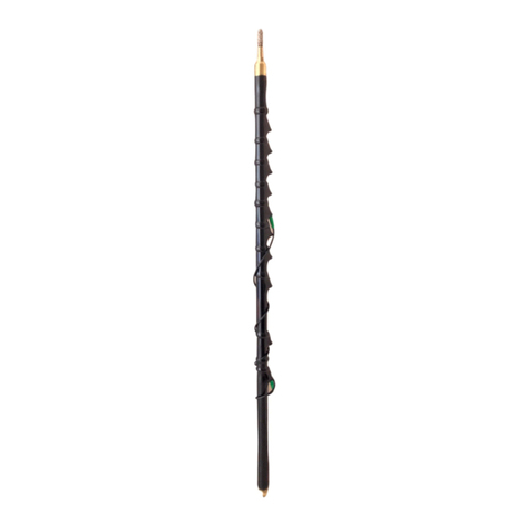
1. FIBERGLASS MAIN SHAFT - Location of h lical coils. Bas mounting PL259 brass nick l-plat d.
2. BAND SOCKETS - Non-corrosiv and silv r-piat d sock ts ar cl arly ngrav d with band markings. Th s sock ts ar
us d for s l cting a band of op ration.
3. WANDER LEAD - Insulat d 32" l ngth of strand d wir with banana plug on ach nd. Us d for 80m through to 2m
op rations. On nd should b plugg d into th WL-32 sock t and th oth r into th d sir d band sock t. Must b wound
(count r/clockwis ) from th bottom up, with coils v nly spac d and n ith r taut, nor hanging loos ly. R mov compl t ly
from ant nna for 75m op ration.
4 STINGER/ TIP/ TUNING ROD or SPIKE - St l rod which xt nds up to 15" out of ant nna shaft. Us d for fin tuning
SWR.
5 KNURLED LOCKING NUT - Locat d at th top of th ant nna shaft. Us d for holding STINGER in plac - finger tighten
only.
TUNE-UP AND OPERATION
Th Outback r Jo y ant nna is d sign d to b us d in conjunction with low pow r portabl transc iv rs (20 Watts PEP
Max). On most transc iv rs a right angl PL259 adapt r to mount th ant nna on th r ar of th transc iv r is
r comm nd d. It is not r comm nd d that th ant nna b us d portabl wh n conn ct d to front mount d BNC typ
sock ts. Physical damag to th front pan l may occur
B st r sults will b obtain d wh n th transc iv r is plac d on th ground with th ant nna plac d v rtical to th ground and
a 12 foot count rpois wir is conn ct d th arth tag on th transc iv r.
1 . Wh n att mpting to tun th ant nna, stand as far away from th unit as possibl as th proximity of th human body
to th ant nna will alt r ant nna r sonanc . NB. Wh n using an ant nna such as th Outback r Jo y on a portabl
abov ground typ transc iv r it is always difficult to obtain constant r sonanc . All m asur m nts at manufactur
w r achi v d with th unit plac d on dry-hard ground with a 12' count rpois attach d.
2. S t th STINGER to th scrib point which is mark d on th STINGER (l ngth from scrib point to tip of STINGER
is 13"). This position (l ngth) stays th sam for all bands oth r than 6m. When sing the O tbacker Joey on 6m
it is necessary to lower the t ning stinger down into the mainshaft ntil only 4" of stinger remains o t A
scribe mark indicates this position as well.
a. For op ration on 40m, tun your transmitt r to 7,250MHz.
b. K y th transmitt r and r ad th SWR m asur d at th transmitt r. If SWR r ads gr at r than 2:1, go to St p
C. If l ss than 2:1, go to St p D.
c. If SWR is gr at r than 2:1, tun your transmitt r to 7.295MHz and ch ck th SWR th r . If th SWR
incr as s at this fr qu ncy, this indicat s th anl nna is too long and is r sonating "low." You will want to
short n th STINGER about 1/4 inch, by loos ning th KNURLED LOCKING NUT and making th
adjustm nt. Th n r -tight n with fingers only. If th SWR d cr as s at this fr qu ncy, your ant nna is too
short and you will n d to l ngth n th STINGER by following th sam proc dur s as for short ning.
Continu this proc ss until th SWR, as m asur d at th transmitt r, is as low as passibl at your d sir d
op rating fr qu ncy on 40m.
d Provid d your SWR is suffici ntly low (l ss than 2:1 at th middl of th 40m phon band), in most cas s all
that is n c ssary to do wh n changing bands, is lo mov th top banana plug on th WANDER LEAD into th
d sir d sock t for 20m, 17m, 15m tc. B sur to wrap th WANDER LEAD v nly and count r clockwis ,
but not too tightly against th shaft. You can mak fin -tuning adjustm nts by moving th STINGER up or
down.


