Outbacker OB8 User manual

INSTALLING THE OUTBACKER
OB8 / OB8-500 / SPLIT / TRI - SPLIT / OB8JR
INTRODUCTION
Thank you for purchasing th OB8. Pl as tak a f w mom nts to car fully r ad these instructions before installing
your ant nna. This will nsur that your mobil s t-up works and works w ll!
Lik all OUTBACKER® ant nna, th OB8 is construct d of a v ry tough, y t fl xibl , fib rglass cor . This cor is
th n h lically wound with copp r wir , which is hand-tun d to th various "tap" points. A coating of cl ar poxy r sin
is th n appli d. Finally a lay r of colour d polyur than is appli d as a prot ction against th l m nts. All fittings on
th ant nna ar solid brass and nick l-plat d. Th 3/8" x 24tpi stud is mad of tough, high-str ngth, stainl ss st l.
DESCRIPTION OF COMPONENTS
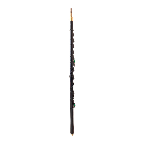
1. FIBERGLASS MAIN SHAFT - Location of h lical coils. Bas mounting stud is stainl ss st l with
standard 3/8" x 24 thr ads.
2. BAND SOCKETS - Non-corrosiv and silv r-plat d sock ts ar cl arly ngrav d with ba d markings.
Th s sock ts ar us d for s l cting a band of op ration,
3. WANDER LEAD - Insulat d 51" l ngth of strand d wir with banana plug on ach nd. Us d for 75m
through to 10 m op ration (80m to 10m if a te a is fitted with 160m). On nd should b plugg d into th
WL sock t and th oth r into th d sir d band sock t. Must b wound (count r- clockwis ) from th bottom
up. with coils v nly spac d and n ith r taut, nor hanging loos ly. R mov compl t ly from ant nna for 80m
op ration (applicable to 160m if fitted).
4. STINGER/ TIP/ TUNING ROD - St l rod which xt nds up to 6" out of ant nna shaft. Us d for fin
tuning SWR.
5. KNURLED LOCKING NUT - Locat d at th top of th ant nna shaft. Us d for holding STINGER
in plac -fi ger tighte o ly!
MOUNTING YOUR OB8
Corr ct mounting of your OB8 is of utmost importanc to obtain succ ssful ant nna p rformanc .
Tru k Lip a d Hatch Mou ti g
Wh n mounting in ith r of th s typ s of configurations, pl as mount th ant nna as far from th roof lin of your
v hicl as possibl . B sur that th surfac of th trunk lip and und rn ath th lip is cl an and that th r is solid
l ctrical contact from th mount to th trunk lip. H r is an asy way to do that.
Fit th mount in plac and tight n its s t-scr ws, th n "back out" s t-scr ws and r mov mount. Look at
ind ntation points l ft by s t-scr ws. Us your pock t knif to scrap off pain! at thos points, xposing shiny m tal.
R install mount, nsuring s t-scr ws fit into scrap d-cl an-of-paint points and ar in contact with shiny m tal. Ch ck
your mount and ant nna occasionally to nsur v rything r mains snug. OUTBACKER® assumes no liability for
antennas lost as a result of loose mounts, or luirchvure.
Luggage compartme t / Tru k lip mou ti g arc not recomme ded for a te a over 4ft i le gth.
INSTALLATION
The OB8 can b i stalled on cars, trucks, RVs. and for fix d op ration (condos, apartm nts, tc.). As with any
ant nna syst m, th r ar no sp cific rul s to follow. How v r, h r ar som h lpful sugg stions.
1 Mount as high as possibl , a d as far away from oth r v rtical m tal ar as as possibl . If mounting in a condo,
us a m lal balcony rail wh r possibl , or thr -inch wid copp r foil (minimum 20 ft. l ngth) for count rpois .
2. Th optimum mounting location for any mobil , is d ad c ntr of th v hicl roof. How v r, sinc this is not
usually practical for most HF ant nnas, mount your ant nna on th driv rs sid trunk of the v hicl to avoid tr
limbs, tc. (s Tru k Mounting s ction).
3. Us high grad 52-ohm RG-58cu coax, or similar, with at l ast 95% shi ld. Marin grad coax is the b st. Do not us foam
coax as il will d form in h at and absorb moistur . Avoid solid c ntr conductor-typ coax as il br aks asily.

7$//0B# %()!%!,)!%! ' !-! !' #
!.!% ! )%!&!! &!! ! ' #
4# %( !%! % ( )% ! !! ! ( !% ! !'!# ! '
' ! !-!%!( !%%')% ! %% #7$77
6 ? 7 0 $8 ? 7C 7
#7+
%% &(! ( )! &!! )% ! !( D '! ( ! ( % 0 (#
(2'! )% %% % !( )!( D (# ! (2'! )% % !( !! !
! %! <% (! ! )% =# %! %% % ( &%% !' E
! <(!!'-%=#
! %' ,&(!( %(%)!((!(' ! %<'' (
! = (2'!)% (! ! !# !!! ! %!%! %%! !( !
D )(, ! % !( ) # ! )'! ' , (( '% ( %
!!(<')'!!% !() !2))!=# %!''!(!( (
%! ! !%!(!%!,! #
9# !''!(!( .&' !6<! %6(%!=(!. -!%!
!%! % !')%!#
!''! ! !&#''! !F%%!(! !( (!$ !%% ,!!
& (! !)!!( !! #
55
!%%& !!' ((!(!,&!%,'! !(!%!,!&
!( ! !*#
5# ! !!!(*%! !-!,'! ! !!%(!( !-!%!)( !
!)!#
3# ! ! ! )! & '!( ! <%! ' )!
1/=#
# 0! 4;', ! ' ! :#39;6G#
)# ! ! ' !(!( !8'!!( ! ' !#8!(! ! 3H5, !
#%! 3H5, !7#
# 8 ! ! 3H5, ! ' ! :#3@96G ( ! ! 8 !!# ! 8
!! !E!, ( ! ! ! %(! /%&#IJ&%%&
! ! ) 524 , ) %! ! 7 ( ' !
(K '! #!!* !$%!*"!(+# !8(!!! !E!, !
( &%% !!( %! ! ! ) %%& ! '! !(! !#
! ! % !8,'!!( ! ' !, %&)%! (!!(
! !E!,4;'#
( $-(!(8! %%&,<%! 3H5 !'((%! !4;'!)(=,' !
%% !! (&!)(, '-! ! )% !877,
!(!!(! 3;',5:',59',! #!! & !877!-!%( !
%&!, ) % ! # J '! !* (K '! ) '- !
(&#
1# ";' <&=! ) !()'%! !!'-% !877# &%%%)!!! ! !
(K %&! 8 !(!!(! !E!#J' (K ! !
%&! 8";'<&=#8 !! !)! , !! !E!.' !%
1#"9;6G<617=#! !! !E!, !#
%(!*%%$ !#( #"%/(#! (# !+ "!4
1-
B6J8*!%%! !, #6!! !877!. !('
!8! (!!()(! #6!! !877!-!%!( &(
! !, !%&!,' !) '#,!'!')!,( & %#%,!'!')!
E !&-!-! %!!(%!'! %2()!! !!#

MODERATELY HIGH SWR - Make sure the antenna is not unusually close ( arallel) to any metal such as the trunk,
or side of an RV or van (see INSTALLATION). Recheck the integrity of your grounding. Try retuning the STINGER
at the desired o erating frequency.
Remember there are more im ortant as ects of mobile installations than having a 1:1 SWR. It is okay and fully
acce table if your SWR should vary from 1:1 to 1:8. Pay s ecial attention to grounding and antenna lacement.
CARE AND MAINTENANCE
All OUTBACKER® antenna are fitted with a rubber "O" ring inside the ti to revent water entering the mainshaft,
however, condensation will accumulate on the inside of the shaft, do not be alarmed. This condensation will not harm
the antenna, nor will it cause inferior erformance. Just remove the KNURLED LOCKING NUT and shake out any
water. Check your antenna after heavy rain.
To clean your antenna, wash it with warm, soa y water and wi e dry with a soft cloth. A ly a thin coating of non-
abrasive, car wax. Buff the antenna to a shine. Do not use cleaners with an acetone base as this will stri the shiny
coating.
Specifications
Model: OB8 / OB8-500 / SPLIT / TRI-SPLIT / OB8JR
Band Coverage: (160m*)-80m-75m-40m-30m-20m-17m-15m-12m-10m
Feed Im edance: 48-52 Ohms
Power : 100 watts ( e )
Construction: Brass - Stainless Steel - Urethane, 1/4 wave helical.
Mounting: 3/8"x24tpi (UNF) Male thread (Stainless Steel)
Wander ead ength: OB8.OB8-SP IT plug tip to plug tip 51" OB8-500. plug tip to plug tip 55" OB8-TRISP IT plug tip
to plug tip 43" OB8-JR plug tip to plug tip 36"
* OPTIONAL
Supplied with OB8 antenna
Qty Part* Description
1
1x
1x
OBW
OBSP15
Main shaft (Black)
Wander lead
6" short tuning spike. (installed at manufacture)
Optional Part#
OBSB Heavy Duty fixed mount.
OBADP 3/8" unf to 112" bsw Stainless steel adapter.
OBQD 3/8" TO 3/8" Quick disconnect adapter (brass & stainless)
OBMT M-Type to 3/8" adapter, (brass)
Should you discover your OUTBACKER® antenna has been da aged in transit, please notify your supplier, or write to
the anufacturer within seven days. Clai s ade ore than 7 days after delivery will not be recognized.
Outbacker North America, Inc.
214 Second Street
Manchester, KY 40962
Phone (606)598-2029
Fax (606)598-4413
OUTBACKER!®! the renowned HF Amateur Mobile Antenna bridging the gap in worldwide communications.
This manual suits for next models
4
Table of contents
Other Outbacker Antenna manuals
Popular Antenna manuals by other brands
Digital Antenna
Digital Antenna PowerMaxTM 18" Specification sheet

ZyXEL Communications
ZyXEL Communications ZoneDAS user guide

Light Beam Antenna
Light Beam Antenna LBM-17M+20M installation instructions

Amphenol
Amphenol RETU-Ex01 installation guide

ConcealFab
ConcealFab 900134 installation manual
Beam
Beam RST703 installation guide
