Outland Technology UWS-3210 User manual

38190 Commercial Court
Slidell, LA U.S.A. 70458
Ph.(985)847-1104, Fax 1106
Email: [email protected]
WEB: www.outlandtech.com
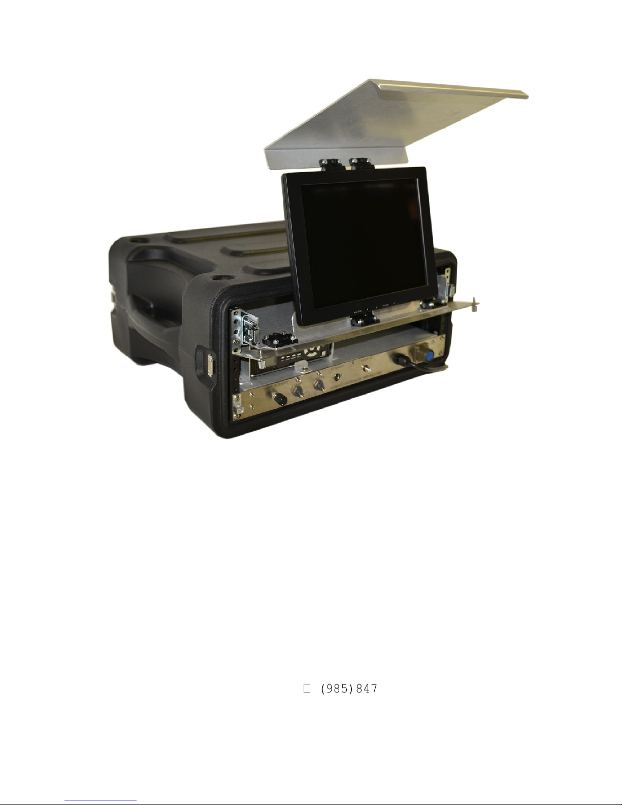
UNDERWATER VIDEO SYSTEM
MODEL UWS-3
2
10

PAGE LEFT BLANK

38190 Commercial Court
Slidell, LA U.S.A. 70458
Ph.(985)847-1104, Fax 1106
Email:
UWS-3210
OPERATING INSTRUCTIONS
1. To operate Camera System, all interconnections from the Control
Unit, VCR & Monitor, should already be connected but in the
event there is a problem drawing # 0010550 shows how those
items connect.
CAUTION:
Insure voltage does not exceed 250 volts AC to
the Console. Also power source must be properly
grounded.
2. Power requirements, Typically 110 VAC to 250 VAC (50 or 60 Hz).
3. Plug Camera Umbilical into Camera and light (Be sure to use a
good quality silicon grease for lubrication). Plug topside
end of umbilical into Control Unit connector on front panel.
4. After verifying supply power is correct, insure camera, light
switches are in off position. Plug into power source.
5. Turn Monitor, Recorder and Camera switches on. A picture should
appear within a few secs.
6. Insure "Light Intensity" is at "Min" position. Turn light
switch on. Turn control up to test light. Turn back to Min.
and Turn switch off.
CAUTION:
" Light can be operated out of water but will
throttle back automatically if the temperature exceeds 50c.
However the Light will never shut off completely.
7. The CON-3200 console only outputs 28 VDC maximum.

8.) To Use the recorder please refer to the DVR manual.
Note:
Read the recorder manual for more details
concerning the operation of these recorders.
Any problems Please Contact: Outland Technology Inc.
38190 Commercial Ct.
Slidell, La. U.S.A. 70458
-1104, Fax (985)847-1106
EMAIL: sales@outlandtech.com
Website: http://www.outlandtech.com

QUICK START TO THE NEW DVR 883b
1) With camera and monitor connected, and on, push the DVR power button.
This takes about 30 secs, to show the main menu. Please wait.
2) To show the camera live, scroll down to “TV”, with the arrow keys and
push the center/enter arrow button to select.
3) If the camera and monitor are connected and on, a picture will appear
quickly.
4) To record, hit the “REC/stop” button and 4 lines will appear:
a. Path, could be C or USB (if a USB device is plugged into the front)
b. Memory size of drive plus how much is available.
c. Video Quality, High is normally selected. Med and low are available.
d. OK and Cancel.
5) “C” is usually highlighted and if you want to record to the internal Hard
drive Just leave it alone.
6) Skip past video quality to OK and select enter (center) button.
7) The unit will start recording and a tiny red dot will appear on the bottom
left side of the screen indicating it is in record.
8) To stop, hit the “REC/stop” button again. It may take a few seconds to
actually say stop on the screen. It is closing the file and if it is large
enough may take 5-10 secs.
9) To playback the video hit the menu button and scroll up to “Recorded files”
Hit the select (center) button to select “Recorded files”.
10) Select which file to play by using the arrow buttons.
Hit the select (center) button to play.
11) To stop the playback hit the “Rec/stop” button.
For more detailed operation of this DVR see the manual supplied with the
system.
Once you get the video files to your computer see the folder VLC in the DVR
hard drive. Download it into your computer and use it to play and pull stills
from the video. This program is free to distribute and use.
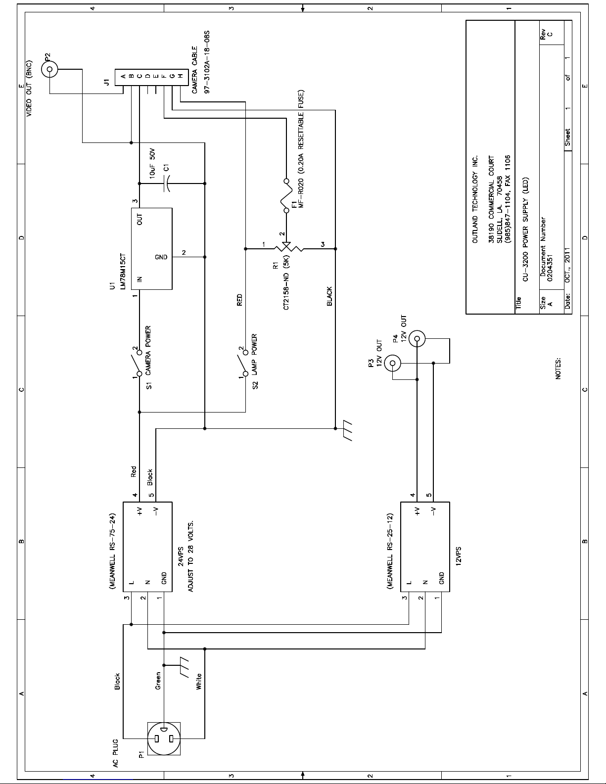
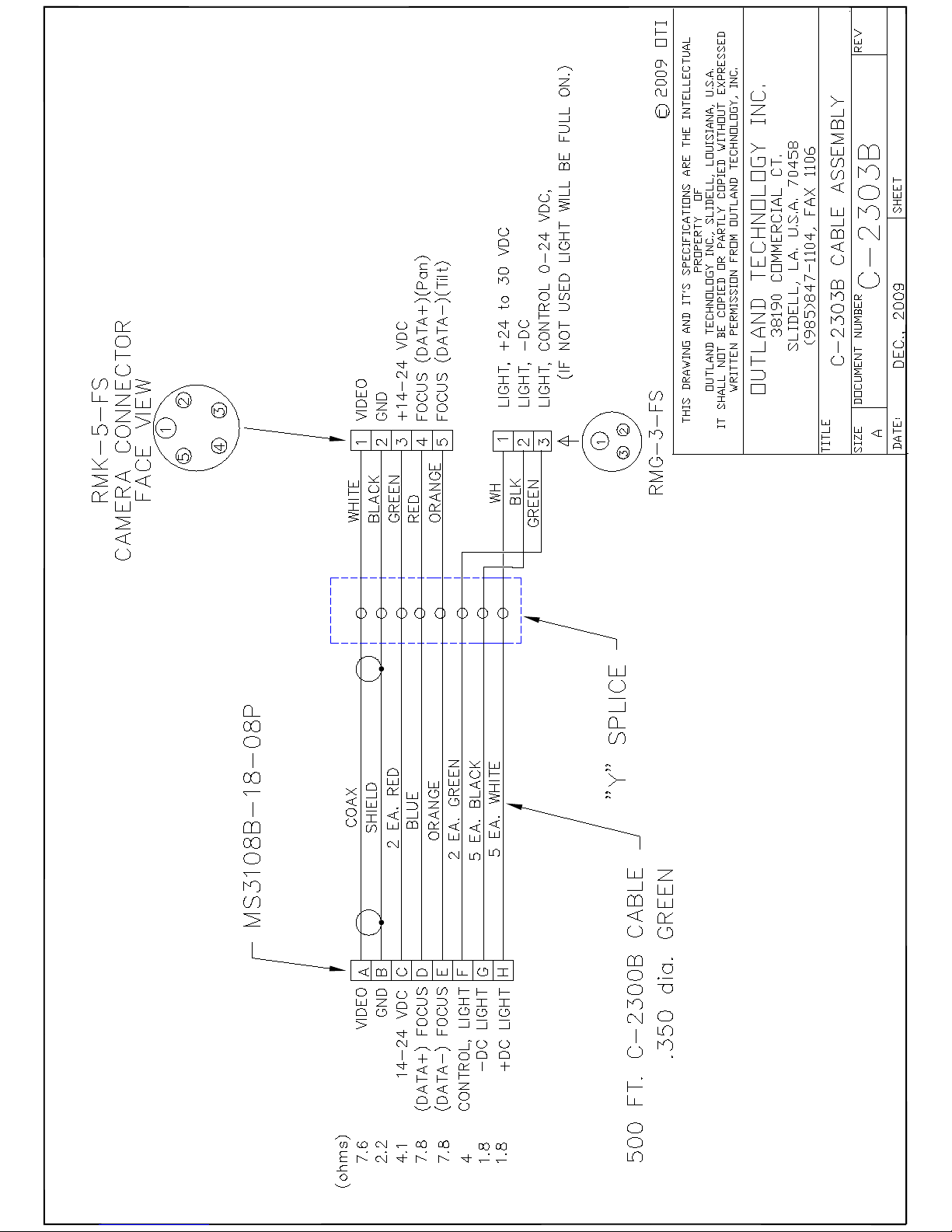


OUTLAND TECHNOLOGY INC.
UWL-401UNDERWATER LIGHT
Operating and Maintenance Procedures
Reference: DRAWING UWL-401
Installation and Operation:
A. The UWL-401, can be mounted to your Camera, ROV, Helmet or Hand
bracket by using DHM-60 OR HM-300 helmet bracket.
B. With Power Off, lubricate the light mating connector with a
light coating of silicon lubricant. Slide the locking sleeve of the
mating connector back. Align the raised dot on the connector with the
large connector pin on the light connector and plug in. Securely
tighten the locking sleeve.
THERE ARE NO USER SERVICEABLE PARTS INSIDE. PLEASE SEND BACK TO THE FACTORY FOR
SERVICE.
The only maintenance required is to flush with fresh water and dry for storage.

38190 Commercial Court
Slidell, LA U.S.A. 70458
Ph.(985)847-1104, Fax 1106
Email: [email protected]
WEB: www.outlandtech.com
LIMITED WARRANTY
Outland has a strong commitment to high quality production. Each product has a twelve (12) month limited
warranty against defects in workmanship or materials with the exception of those outlined in the limitations
and exclusions. Outland will repair or replace at its discretion the defective components.
Limitations and Exclusions
The limited warranty does not cover damage caused by improper use, poor maintenance or
accidental damage of the product or its components.
The limited warranty does not cover items subject to wear including but not limited to view ports,
o-rings, umbilical, unless found to be defective in workmanship and/or materials.
The limited warranty does not cover any modification made to these products without
authorization from Outland Technology Inc.
The limited warranty does not cover lamps.
The limited warranty does not cover components damaged due to incorrect power connection per
user’s manual.
The limited warranty does not cover items not actually built by Outland. Example (DVR recorder,
Monitor etc.). That would be covered by the manufacturer's warranty.
Advertising claims made by us represent our honest opinion of the qualities and features offered by the
products described. We disclaim any warranties expressed or implied, including warranties of merchantability
and fitness for a particular purpose, except as provided herein. In no event shall Outland Technology be
liable for consequential damages of any kind.
Shipping
All returns for warranty service must be authorized by Outland. You must call or email Outland for a
RMA#. The assigned RMA (Returned Materials Authorization) number which must be clearly indicated on
each item returned for service.
NOTE: To submit a product or its components for warranty a RMA form must be completed.
Please complete as best and detailed as possible.
For warranty shipping within the first 30 days, Outland will pay for ground shipment on domestic orders
incoming and outgoing to a maximum of $75.00 each way. International shipments will be credited up to
$75.00 US for incoming and outgoing freight charges to Outland Technology Inc.
After 30 days the client is solely responsible for shipping to and from Outland Technology Inc.
During the first 30 days of the warranty period, should faster delivery service be requested, a $75.00 US
credit towards expedited freight for each applicable leg will be given.
If you have any questions regarding the installation and operation of this equipment, or if more
information is needed contact:
OUTLAND TECHNOLOGY,INC.,
38190 Commercial Ct.,Slidell, LOUISIANA USA 70458
(985)847-1104 FAX (985)847-1106
(Email) sales@outlandtech.com
(Website) http://www.outlandtech.com

TROUBLESHOOTING GUIDE
CAMERA DOES
CAMERA
UMBILICAL NOT
PLUGGED IN AT
CONSOLE OR
MONITOR NOT ON
CAMERA POWER
SWITCH NOT ON.
RECORDER NOT ON
OR IN PLAY MODE
POWER CORD NOT
PLUGGED IN
PLUG IN
NO
YES
NO
CONNECT
YES
NO
TURN ON
NO
TURN ON/
YES
YES
NO
TURN ON
YES
CAMERA
DEFECTIVE
YES
TRY ANOTHER CAMERA.
NO
UMBILICAL HAS A
SHORT OR
BROKEN WIRES
YES
CHECK FOR
CONTINUNITY AND/OR
SHORTS USING
DRAWING #C-2303
NO
CAMERA POWER
SUPPLY IS BAD.
YES
CHECK FOR 12-16 VDC
AT PINS B&C ON POWER
SUPPLY.
LIGHT
DOES NOT
POWER CORD NOT
NO
PLUG IN
LIGHT UMBILICAL
NOT PLUGGED IN
AT CONSOLE OR
CAMERA
YES
NO
CONNECT
UMBILICAL HAS A
SHORT OR
BROKEN WIRES
CHECK FOR
CONTINUNITY AND/OR
SHORTS USING
DRAWING #C-2303
YES
YES

12” TFT-LCD MONITOR
WITH
VIDEO INPUTS
288 Video Series
USER’S MANUAL

The monitor digital control functions are located on the front panel. They
are shown in the figure below and described in the following paragraphs.
1. Power indicator LED
2. Power switch
3. Function keys
Function Selection
1. Press the knob “MENU/SELECT” to show the OSD menu. Then use the
“▲” and “▼” to select a function. Press the knob “AUTO/EXIT” to close
the OSD menu.
2. With the knob “▲” and “▼” , you can adjust the speaker volume on the
monitor.
When you press the “▼”, the speakers are mute. Press the “▲” and
then the speakers are active.
When you press the knob “▲” , the speaker volume OSD is shown.
You can increase or decrease the volume by pressing the “▲” and
“▼”.
3. You can hold the knob “AUTO/EXIT” for more than 1 second to adjust the
image quality automatically.
The OSD menu will close automatically after 3-10 seconds without operation
and saves any changes you have made.
Function Adjustments
1. Signal Select
When there is no OSD menu display the knob “AUTO/EXIT” can select
VGA / DVI / CVBS / S-VIDEO.
1. Control Functions

2. Video
Contrast -Adjust the difference in luminance between light and dark
areas of the image.
Brightness - Adjust the luminance level of the image.
Colour -Adjust the Color level of the image

Tint - Adjust the Tint level of the image
Sharpness - Adjust the Sharpness level of the image
Video Mode - Adjust the Video Mode for
Normal/Nature/Cinema/Sport/Vivid

Reset -
Recall the factory setting of the Vide menu.
ontrast -Adjust the difference in luminance between light and dark
areas of the image.
VGA
C
Brightness - Adjust the luminance level of the image.
8

9
harpness - Adjust the Sharpness level of the image
olor Temperature
Cool(9300k)/User/Warm(6500k)/Nature(7500k)
User RGB -
S
C -Adjust Color Temperature
Adjusting R/G/B level of the image

Image
uto Tune -
osition - Adjust the vertical & horizontal position of the image.
hase - Adjust the horizontal sync phase of signal.
- Adjust the horizontal sync size of signal.
Reset
3. Audio (Video &
V
A Adjust geometry of the image automatically.
P
P
Clocks
- Recall the factory setting of the VGA menu.
VGA)
olume - Adjust the speaker volume.
Table of contents