OXTS GPS-Base User manual

Confidently. Accurately.
GPS-Base
GPS
Base
Station
GPS-Base
User Manual

2 Oxford Technical Solutions
Legal Notice
Information furnished is believed to be accurate and reliable. However, Oxford
Technical Solutions Limited assumes no responsibility for the consequences of use of
such information nor for any infringement of patents or other rights of third parties
which may result from its use. No license is granted by implication or otherwise under
any patent or patent rights of Oxford Technical Solutions Limited. Specifications
mentioned in this publication are subject to change without notice and do not represent
a commitment on the part of Oxford Technical Solutions Limited. This publication
supersedes and replaces all information previously supplied. Oxford Technical
Solutions Limited products are not authorised for use as critical components in life
support devices or systems without express written approval of Oxford Technical
Solutions Limited.
All brand names are trademarks of their respective holders.
Copyright Notice
© Copyright 2013, Oxford Technical Solutions.
Revision
Document Revision: 131025 (See Revision History for detailed information).
Contact Details
Oxford Technical Solutions Limited
77 Heyford Park
Upper Heyford
Oxfordshire
OX25 5HD
England
Tel: +44 (0) 1869 238 015
Fax: +44 (0) 1869 238 016
http://www.oxts.com
mailto:[email protected]

GPS-Base User Manual
Revision: 131025
3
Table of contents
Introduction 5
Overview 5
Correction types 6
File logging 7
Features 7
Scope of delivery 9
Specification 11
Warranty 12
Conformance notices 13
Regulatory testing standards 13
Operation and configuration 14
Choosing a suitable location 14
Connections 14
GPS-Base software 16
Choosing the connection 16
Choose port 17
Scan ports 17
Remember this port selection 18
Configuring the GPS-Base 18
Average position 19
Restore position from file 19
Enter antenna position 20
Leave unchanged 20
Advanced 20
Status page 21
Status 22

4 Oxford Technical Solutions
Communication 23
Latitude, longitude, altitude 23
Base Station ID 23
Logging Novatel binary 23
Logging RTCM V3 24
Save position to file 24
Start logging 25
LED status 26
SATEL radio status 26
Freewave radio status 26
Discussion on repeatability 28
Differential correction format details 30
Revision history 32

GPS-Base User Manual
Revision: 131025
5
Introduction
The GPS-Base is a GPS Base Station suitable for transmitting differential corrections to
the OxTS RT3000, RT4000, RT2002, RT2004, Survey+ and OEM products that use
GPS. The position accuracy of differential and RTK GPS receivers is improved when
using the GPS-Base.
Four models of the GPS-Base exist, as listed in Table 1. All models are identical in
their operation but are able to track different satellite signals.
Table 1. GPS-Base Models
Model Measurement
GPS-Base-20 L1 GPS corrections suitable for 20cm positioning
GPS-Base-20G L1 GPS and L1 GLONASS corrections suitable for 20cm positioning. Some RT
products can achieve 2cm accuracy using this model.
GPS-Base-2 L1/L2 GPS corrections suitable for 2cm positioning
GPS-Base-2G L1/L2 GPS and L1/L2 GLONASS corrections suitable for 2cm positioning
The GPS-Base is available with several different radio options. Different radios are
required for license free operation in different countries.
Overview
Figure 1 gives an overview of how differential GPS works. The information from each
satellite is measured by both the GPS-Base and by the GPS in the car. The GPS-Base
works out the error in the satellite’s information and transmits it to the car using a radio
link. The GPS in the car then applies the correction to each satellite’s measurement
before it computes position and time.

6 Oxford Technical Solutions
Figure 1. Differential GPS overview
For RTK (Real-Time Kinematic) carrier-phase measurements the principle is the same,
but the GPS in the car also has to figure out the difference in the number of carrier-
phase cycles between the GPS-Base and the car. The GPS-Base measures the carrier-
phase of the signals from each satellite and transmits it to the car.
Differential GPS works in real-time because the corrections from each satellite vary
slowly and predictably. The GPS in the car uses a model to predict the error from each
satellite. It can update its model when the radio link transmits new data. It is not
necessary for the GPS in the car to wait until the radio has transmitted the correction
before it outputs its latest value.
Correction types
The GPS-Base can transmit differential corrections in different formats. The
recommended format for OxTS products is RTCA (GPS-only) or RTCA2 (GPS and
GLONASS). The RTCM V3 format can also be used. Table 2 lists the different formats
supported by the GPS-Base and gives their suitability to other OxTS products.

GPS-Base User Manual
Revision: 131025
7
Table 2. Differential correction formats supported by the GPS-Base
Format Purpose
RTCA The RTCA format is suitable for GPS differential corrections for the RT3000,
RT4000 and RT2002 products. The RTCA format is compatible with older RT3000
products (serial numbers below about 150). The RTCA format is not suitable for
GLONASS.
RTCA2 The RTCA2 format is suitable for GPS and GLONASS differential corrections for
the RT3000, RT4000, RT2002 and RT2004 products. It is not compatible with older
RT3000 products (serial numbers below about 150).
RTCM V3 The RTCM V3 format is suitable for GPS and GLONASS differential corrections for
the RT3000, RT4000 and RT2002 products. It is not suitable for RT2004 products.
More detailed information on the different formats is given at the end of the manual in
the section called “Differential correction format details”.
File logging
The GPS-Base software can log data on to the hard disk of the PC. Files can be logged
in Novatel binary format and in RTCM V3 format.
Features
The GPS-Base is a self-contained unit that includes:
The Base-Station GPS receiver.
External Radio Modem.
GPS Antenna, 15m Cable and Tripod.
Radio Modem Aerial, Cable and Magnetic Mount.
All that is needed to operate the GPS-Base is an external power source (normally a
battery) and a PC or Laptop.
The GPS-Base also includes a radio modem and antenna for use on the vehicle.
The radio modem in your GPS-Base will be factory configured for use in a particular
country or territory. Typically the radio can transmit between 2 km and 5 km line-of-
sight. Trees, buildings, hills and other obstructions limit the range that can be used.
Table 3 lists the different radio options that are commonly used with the GPS-Base.

8 Oxford Technical Solutions
Table 3. Overview of different radios
Radio Specification
SATEL 380 - 480 MHz band, up to 1 W, typically 5 km. License free bands
available for many European countries. Radio will typically cover 8 bands
with 25 kHz channel spacing.
SATEL 869 MHz band, up to 500 mW, typically 2 km. License free across most of
European Union.
Freewave 900 MHz band, up to 1 W, typically >10 km. License free in USA, Brazil,
Canada.
Futaba 2.4GHz band, 10mW, typically more than 1km. License free in Japan.

GPS-Base User Manual
Revision: 131025
9
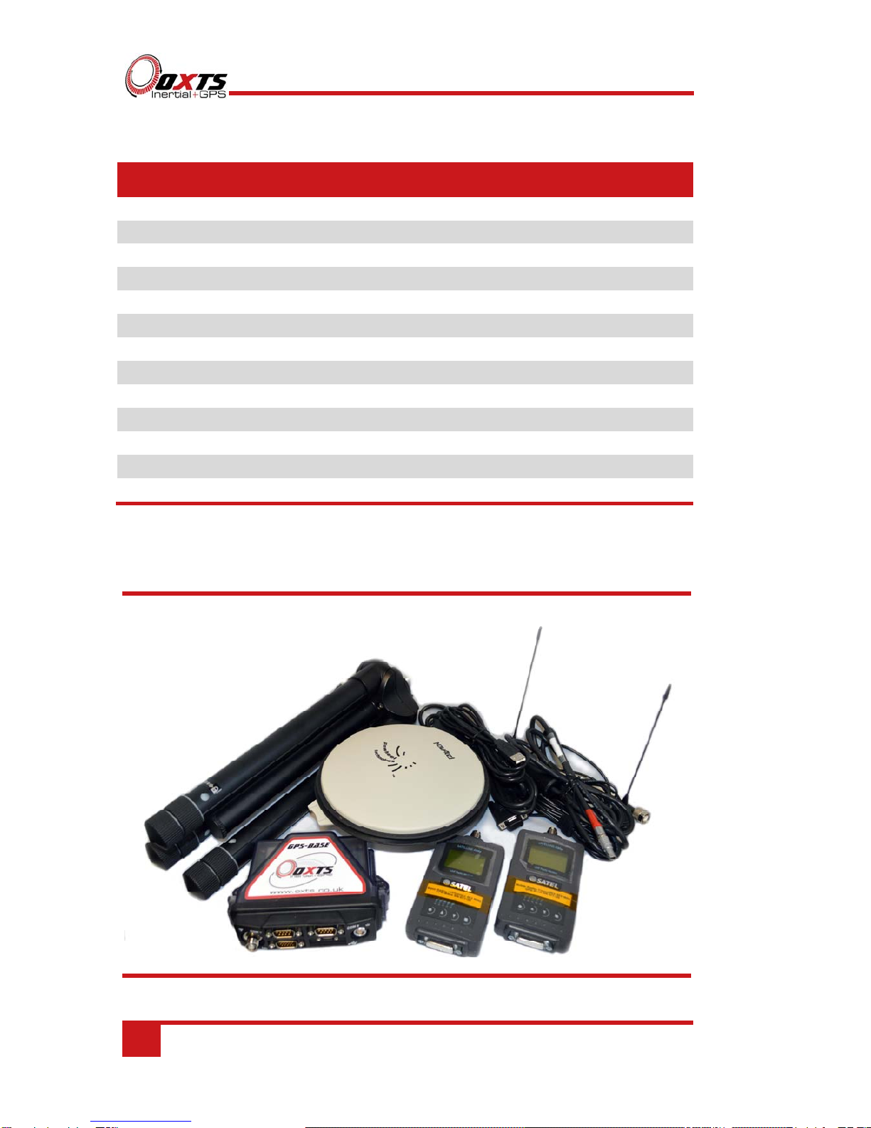
Scope of delivery
Table 4, and Table 5, list all the items that are delivered with a GPS-Base and the
respective radio modem.
The customer must check that the radio can be used without a license or obtain a
suitable license before using the GPS-Base. Oxford Technical Solutions cannot be held
responsible for using this equipment illegally without the correct radio license.
Table 4. Summary of the GPS-Base components with SATEL radio
Qty Description
1 GPS-Base Unit
1 GPS-C006 15m GPS Antenna Cable
1 GPS-702-GG GPS Antenna
2 SATEL Satelline-3ASd Radio Modem
2 Radio Modem Aerial/Antenna with 3m cable and Magnetic Mount
1 Tripod
1 Power cable
1 Radio modem cable
1 PC-USB cable
1 GPS-Base User Manual
1 GPS-Base Quick Guide
10 Oxford Technical Solutions
Table 5. Summary of the GPS-Base components with Freewave radio
Qty Description
1 GPS-Base unit
1 GPS-C006 15m GPS antenna cable
1 GPS-702-GG GPS antenna
2 Freewave FGR-115RC 900 MHz radio
2 14C0044B Freewave radio cable
1 Car antenna (short) with 20ft cable
1 Base-station antenna (long) with 20ft cable
1 Lightweight tripod
1 Power cable
1 Radio modem cable
1 PC-USB cable
1 GPS-Base user manual
1 GPS-Base quick guide
Figure 2. GPS-Base components with SATEL radios
Table of contents
Other OXTS GPS manuals


