5
Introduction
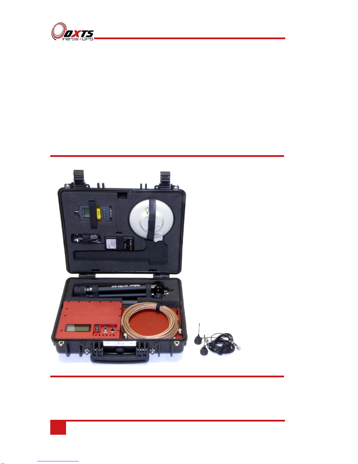
The RT-Base S is a self-contained, weatherproof and portable GNSS base station. It is
designed to be quick and easy to set-up, and transmits corrections to local receivers via
radio modem or (optionally) via Wi-Fi.
In addition to outputting differential corrections for use in real-time, the RT-Base S has
the ability to log corrections internally—allowing them to be used in post-processing.
This is especially useful when operating in challenging real-world environments
because it means no data is lost where the reliability of radio transmissions cannot be
guaranteed.
There are two versions of the RT-Base S:
RT-Base S
Supplies L1/L2 GPS corrections down to 1 cm accuracy.
RT-Base S G
Supplies GLONASS and L1/L2 GPS corrections down to 1 cm accuracy.
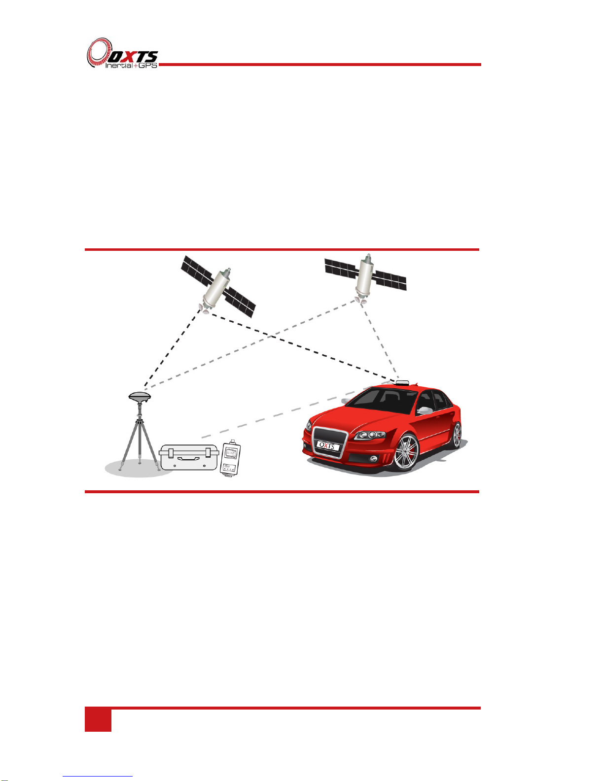
How do base stations work?
A base station significantly increases the position accuracy of other GNSS receivers by
sending them corrections. The base station does this by independently identifying the
errors affecting the signal from each GNSS satellite it can see. Information about those
errors is then broadcast using a radio modem, or something similar. Other GNSS
receivers in the area—which are also connected to similar radio modems—receive the
correction information and take it into account when calculating their own position
measurements. Removing the errors results in more accurate position estimates.
A base station identifies the errors affecting GNSS signals in one of two ways. If the
base station is placed at a precisely surveyed location, it calculates a GNSS position
measurement in the normal way, then compares that calculated position to the known
location. If the position measurements match exactly, no correction is required. If there
is a difference however, the base station calculates the length of time each satellite
signal would need to be delayed by, in order to cause the difference between the
surveyed location and the GNSS measurement being produced.
Alternatively, if the base station is not placed at an accurately surveyed location, the
only way for it to estimate the errors is to measure its own position as accurately as
possible. It does this by averaging the GNSS measurements over a period of time
before settling on one location. It then compares all further measurements to that
chosen location in order to identify the errors in the same way as before.
In both cases the base station calculates the errors affecting the signal from each
satellite it can see, and shares that information with other GNSS receivers in the local