Ozone Solutions ES-600 User manual

Ozone Solutions
sales@ozonesolutions.com
(888) 892‐0303
Ozone Controller, Model ES-600
User Manual, Rev. 1.0
1
OZONE SWITCH
Model ES-600
ES-600 Features
The ES-600 is an industrial grade ozone controller and monitor. The ES-600 design is optimized
foraccuracy and ease of installation, setup and operation.
•Front panel digital LCD displays ozone level.
•Rugged, splash resistant NEMA 4X enclosure for
industrial environments.
•Easily accessible connection terminals and
controls allow the unit to be setup after it is
mounted.
•LED indicators display when ozone exceeds the
0.1 ppm OSHA limit and a variety of other
important ozone control parameters.
•Set points for ozone generator control relays are
digitally controlled with numeric set points. This
makes precise ozone control easy to set up, even
when ozone is not present.
•Ozone generator failure mode detection warns when the connected ozone generator is not
maintaining the desired ozone set points. This option can be disabled.
•“Monitor Mode” can be enabled on the ES-600 panel. This mode disables the ozone generator
controller and generator failure mode status indicators while maintaining ozone measurement
and limit warning indicators.
•Analog outputs (4-20 mA and 0-2 VDC) are compatible with PLCs and other process
controllers.
•Digital serial output (RS-232) allows for convenient connection to a computer. Data output:
ozone (ppb), temperature (°C), and relative humidity (%).

Ozone Solutions
sales@ozonesolutions.com
(888) 892‐0303
Ozone Controller, Model ES-600
User Manual, Rev. 1.0
2
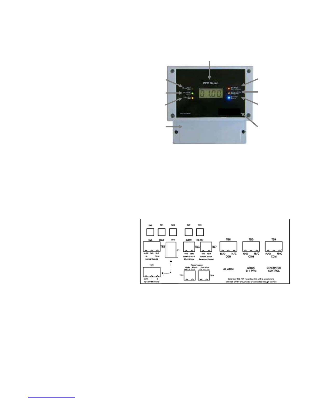
ES-600 Indicator Lights and Display
PPM Ozone: Auto ranging digital display in ppm (parts
per million).
Above MAX Limit: Illuminates when ozone reading is
above the MAX set point.
Data From Sensor: Illuminates and blinks at 1-second
intervals when powered on and receiving data from the
sensor.
Below MIN Limit: Illuminates when ozone reading is
below the MIN set point.
Unable to Control Ozone: Illuminates when the ozone
generator (TB4) is not maintaining the desired set
points. A relay (TB6) engages with this indicator to
provide remote alarm capability. This option may be
disabled by setting the FAIL time to 0999. Refer to “Set
Point and Alarm Condition Settings” for more details.
This option is also disabled when the instrument is in
Monitor Mode. Refer to “External Connections – TB7:
Generator Enable” for more details.
PPM Ozone
Unable to
Control Ozone
Above 0.1 PPM
Safety Limit
Generator
Control
Display
Compartment
Above 0.1 PPM Safety Limit: Illuminates when the measured ozone exceeds 0.1 ppm (OSHA 8-hour time-weighted average safety limit). A
relay (TB5) engages with this indicator to provide remote alarm capability.
Generator Control: Illuminates when the ozone generator relay (TB4) is engaged, indicating the ozone generator is on.
Wiring Compartment: Contains buttons for adjusting set point and alarm conditions as well as wiring terminals for sensor module
connections, ES-600 power input, analog outputs, relay outputs, and Monitor Mode selector.
Display Compartment: Contains jumper pins for selecting the analog output full-scale range.
External Connections
The wiring terminals for the sensor module connections,
ES-600 power, analog outputs, relay outputs, and Monitor
Mode selector are located in the Wiring Compartment. For
access, disconnect the ES-600 from power and remove
the two screws and cover. The connection board will
resemble this diagram.
TB1: 12-24 VDC POWER: Power input and earth
grounding for the ES-600
TB2: ANALOG OUTPUT: 4-20 mA and 0-2 VDC to
external control equipment. Refer to “Analog Range
Selection” for details. Default range is 0-20 ppm. NOTE:
the 4-20 mA output is a DRIVER rather than a current-sink
type output.
TB3: RS-232 OUTPUT: Serial data output. Refer to “Data Connection” for details.
TB4: GENERATOR CONTROL: Relay contacts with user adjustable control limits for operating an ozone generator. Refer to “Set Point and
Alarm Condition Settings” for details.
TB5: ABOVE 0.1 PPM: Relay contacts tied to OSHA human safety limit (for remote indicator/alarm).
TB6: UNABLE TO CONTROL OZONE: Relay contacts tied to Unable to Control Ozone error condition (for remote indicator/alarm).
TB7: GENERATOR ENABLE: A jumper is installed at the factory to enable Generator Control (TB4). If the jumper is removed and these
terminals are not connected, an ozone generator connected to TB4 will never run. Remove the jumper or replace it with a switch to disable the
ozone generator when performing maintenance. Also remove the jumper to operate the ES-600 in “Monitor Mode”. In this state, when the
jumperis removed, the Generator Control relay (TB4) will be disabled, as well as the “Generator Control” indicator and the “Unable to Control
Ozone” indicator.
TB8: SENSOR DATA AND GROUND: Connect data and ground (black) conductors from SM-module, TB1 to ES-600, TB8. Refer to Appendix
Afor an illustration and more details.
Use either
Above MAX
Limit
Data From
Sensor
Below MIN
Limit
Wiring
Compartmen
[Gra
b
your
read
er’s
atten
tion
with
a
great
quot
e
from
the
docu
ment
or
use
this
spac
e to
emp
hasiz
e a
key
point
. To
place
this
text
box
anyw
here
on
the
page
, just
drag
it.]

Ozone Solutions
sales@ozonesolutions.com
(888) 892‐0303
Ozone Controller, Model ES-600
User Manual, Rev. 1.0
3
TB9: SENSOR POWER: Refer to Appendix A for an illustration and more details. Connect power conductor (red) from either:
+5 V out to SM-module TB1 +5 V
OR
+12-24 V out to SM-module TB2 +12-24 V
WARNING: Do not connect ‘+12-24 V Out’ terminal on the ES-600 to the SM-module TB1 ‘+5 V’. This will damage the SM-module
and void the warranty.
Power Connection
Disconnect power before opening the case to access the ES-600. Use only one of the following two methods to power the ES-600:
1.
AC Adapter (included): 12-24 VDC, 300 mA (minimum), barrel connector. Refer to Tech Note P-101 at
www.ecosensors.com/support for additional AC adapter specifications.
2.
TB1: 12-24 VDC, 300 mA (minimum), wired connection (16-26 gauge)
Initial Operation & Warm-Up
All standard connections between the ES-600 and the SM-module are made at the factory. Once power is connected to the ES-600 using one
of the methods described above, the green power/data LED will illuminate and then blink at a 1-second interval as data is received from the
SM- module. The LCD will display digits.
Power the ES-600 and connected SM-module for 1-hour before response testing. Prior to on-site process integration, operate on power for 24
hours. We recommend testing the instrument for positive response with an ozone generator when the instrument is received and again at the
site where the instrument is installed.
Set Point and Alarm Condition Settings
Five push-buttons are mounted on the circuit board
behind the wiring compartment cover. Remove the cover
(two screws) and locate the buttons in the upper-left
corner. From left to right, they are: FAIL, MAX, MIN,
INCR and DECR.
FAIL: Time (in minutes) that the ozone level can remain
above MAX set point or below MIN set point before the
'‘Unable to Control Ozone” indicator and relay engage. To
disable the “Unable to Control Ozone” indicator and relay
(TB6), set FAIL to 0999 (available on instruments shipped
after 2012-10-15, call us for details).
MAX: Maximum ozone set point at which the generator is
turned off.
FAIL MAX MIN INCR DECR
MIN: Minimum ozone set point at which the generator is turned on.
INCR: Increase set point value.
DECR: Decrease set point value.
Change a set point by pressing FAIL, MAX, or MIN. The current value of that set point will appear on the display. Press INCR or DECR to
adjust the value. MIN will not adjust higher than MAX.
Use either

Ozone Solutions
sales@ozonesolutions.com
(888) 892‐0303
Ozone Controller, Model ES-600
User Manual, Rev. 1.0
4
Data Connection
Data from the ES-600 and connected SM-module can be received by a computer via RS-232
serial cable. Basic communication parameters are listed in the table to the right. For more
details please consult the RS-232 Communication Manual, available at
www.ecosensors.com/support.
Serial data is updated from the SM-module approximately once per second. An example serial
data output stream is given below for 1 ppm ozone, 23 °C, and 33% relative humidity:
Ozone (ppb), Temperature (°C), and Relative Humidity (%):
1000, 23, 33
Analog Output Full Scale Selection
The full-scale range for the 0-2 V and 4-20 mA analog outputs may be
selected by adding or removing up to three push-on jumpers on header
J4, located on the back of the display circuit board. Access this area by
removing four screws from the display bezel.
Changing the analog output full-scale range will not change the ES-600
display, which will always read in the within range 00.00 to 99.99 ppm.
The actual measurement range of the ES-600 display is determined by
the attached SM-module. Refer to the specification sheet of the attached
SM-module to determine the measurement range.
The ES-600 is shipped from the factory with the Analog Output Full Scale
Range set to match the installed SM-module. For further details, refer to
the specification sheet of the attached SM-module.
Specifications
Enclosure: Wall mounted polycarbonate enclosure resists water spray and splash (NEMA 4X).
Size: H = 6.3”/160mm, W = 6.5”/166mm, D = 4.6”/118mm.
Wiring: Conduit or cable gland knock-outs along bottom of enclosure.
Power in: 12-24 VDC.
Power out: +5 or +12-24 VDC to sensor.
Data in: RS-232 serial data from remote sensor module (SM-module).
Data out: RS-232, 9600 baud, 8N1 format.
Analog out: 0-2 V and 4-20 mA, internal jumpers select full scale ppm range.
Control in: Generator enable (contact closure).
Control out: Relays: 12 A @ 30 VDC (resistive load), 12 A @ 250 VAC (resistive load).
Relay functions: Ozone generator control, >100 ppb safety limit, failure to control ozone.
User controls (internal): MAX set point, MIN set point, FAIL time, increase, decrease.
Numeric display: 4-digit, 0.5” (12 mm), auto-ranging, backlight.
LED indicators: Sensor, above MAX, below MIN, >100 ppb, O3generator control, failure.
Serial Communication Parameters
Parameter
Speed (baud)
Data bits
Stop bits
Parity
Flow Control
Value
9600
8
1
None
None
J4 Jumper Positions
A B C
OFF OFF OFF
ON OFF OFF
OFF ON OFF
ON ON OFF
OFF OFF ON
ON OFF ON
OFF ON ON
ON ON ON
Analog Output Full-
Scale Range (ppm)
0-2
0-5
0-10
0-20
0-50
0-100
0-200
0-500

Ozone Solutions
sales@ozonesolutions.com
(888) 892‐0303
Ozone Controller, Model ES-600
User Manual, Rev. 1.0
5
Notes and Precautions
•
Disconnect power before connecting or disconnecting wires in the case.
•
After connecting power, allow 1 hour for warm-up before testing. Allow 24 hours for warm-up before continued use.
•
Keep the instrument dry.
•
Do not drop the instrument or subject it to continuous vibration.
•
Do not store or use the instrument in areas with high levels of dust.
•
Do not clean the instrument with cleaning chemicals or solvents. If necessary, wipe clean with a damp cloth.
•
Do not operate the instrument in environments with combustible gases and materials.
•
Call a qualified electrician if you have any questions regarding electrical wiring codes.
Service and Maintenance
•Tampering with the unit or attempting repairs will void the warranty. Repairs should only be performed by Ozone Solutions or an
Ozone Solutions authorized service representative.
•Instruments with problems during the warranty period should be returned as a system to the factory or authorized service representative
for diagnosis and repair.
•We recommend checking the calibration monthly and changing the user replaceable sensor annually. It is generally more cost effective to
replace sensors than to recalibrate them.
•Always remove power from the ES-600 and SM-module before opening the case. Follow the Wiring Diagram in Appendix A.
Warranty
This product is warranted against defects in materials and workmanship for one year following the date of purchase by the original owner. This
warranty does not include damage to the product that results from misuse, accident, dropping, modifications or alterations, and it does not
apply if the instructions in this manual are not followed, or if the unit is otherwise used outside its intended specifications.
If a defect develops during the warranty period, Ozone Solutions, in its sole discretion, will repair the instrument or replace it with a new or
reconditioned model of equivalent quality. In the event of replacement with a new or reconditioned instrument, the replacement unit will
continue the warranty of the original unit.
If the product should become defective during the warranty period, please return it through your distributor, or call Ozone Solutions at (888)
892-0303 or e-mail at sale[email protected] to receive return instructions and a Return Materials Authorization (RMA) number.
Except as provided herein, Ozone Solutions makes no warranties, express or implied, including warranties of merchantability and fitness for a
particular purpose. Ozone Solutions shall not be liable for loss of use of this instrument or other incidental or consequential damages,
expenses oreconomic loss, or claims for such damage or economic loss.
RECORD YOUR SERIAL NUMBER HERE
KEEP THIS MANUAL AND WARRANTY FOR YOUR RECORDS.
Ozone Solutions is a registered trademark of Ozone Solutions, Division of KWJ Engineering, Inc.
© Ozone Solutions, Division of KWJ Engineering, Inc. 2013.
For brochures, application and tech notes, and other useful information, visit our extensive website at www.ecosensors.com. E-mail us at
sales@ozonesolutions.com.

Ozone Solutions
sales@ozonesolutions.com
(888) 892‐0303
Ozone Controller, Model ES-600
User Manual, Rev. 1.0
6
OS-6 Wiring Compartment Panel
Appendix A
SM-Module Wiring Illustration #1
(Typical)
ES-600 Wiring Compartment Panel
Use either
Power In 3-Wire Cable
GND 12-24 VDC
Power Out
Data In GND 5VDC
User Replaceable
Sensor Connects Here
WARNING: Never connect ES-
600 TB9: +12-24 V to SM-module
TB1.This will damage the SM-
module and void the warranty
SM-Module
SM-Module Wiring Illustration #2
(Alternate)
Use either
Power In 3-Wire Cable
GND 12-24 VDC
Power Out
Data In GND 12-24 VDC
User Replaceable
Sensor Connects Here
WARNING: Never connect ES-
600 TB9: +12-24 V to SM-module
TB1.This will damage the SM-
module and void the warranty SM-Module

Ozone Solutions
sales@ozonesolutions.com
(888) 892‐0303
Ozone Controller, Model ES-600
User Manual, Rev. 1.0
7
ES-600 Wiring Options Illustration
Analog Outputs to
Process Controller
4-20 mA Out
0-2 VDC Out
Serial RS-232
ES-600 Wiring Compartment Panel
Use either
Refer to SM-Module Wiring Illustrations
TB7 Options:
No Connection Monitor Mode
Jumper Generator Control
Switch Selectable Monitor
Mode or Generator
Control
N/O COM N/C
Generator Control Relay
N/O COM N/C
Alarm Relay:
Above 0.1 ppm OSHA Safety Limit
N/O COM N/C
Alarm Relay:
Unable to Control Ozone
(ozone level outside set-points)
Appendix B
ES-600 Application Diagram
(for reference only)
ES-600 SM-module Connection * A power relay is required if the load exceeds the
ES-600 relay ratings
Computer (Optional)
Ozone Generator
Ozone Area
Power Relay*
Exhaust Fan
(optional)
RS-232 Output
Relay Output*
Power Relay*
Table of contents
Popular Switch manuals by other brands

Pilz
Pilz PSEN cs6.2p operating manual

Festo
Festo SME-1 Series operating instructions

D-Link
D-Link DGS-1216T - Switch manual

Zigen
Zigen SW-42Plus quick start guide

Blendom
Blendom di3g.yriafu.01.02.zb instruction manual

Brocade Communications Systems
Brocade Communications Systems Brocade 6520 Hardware reference manual