PAC PAC-350WM Guide

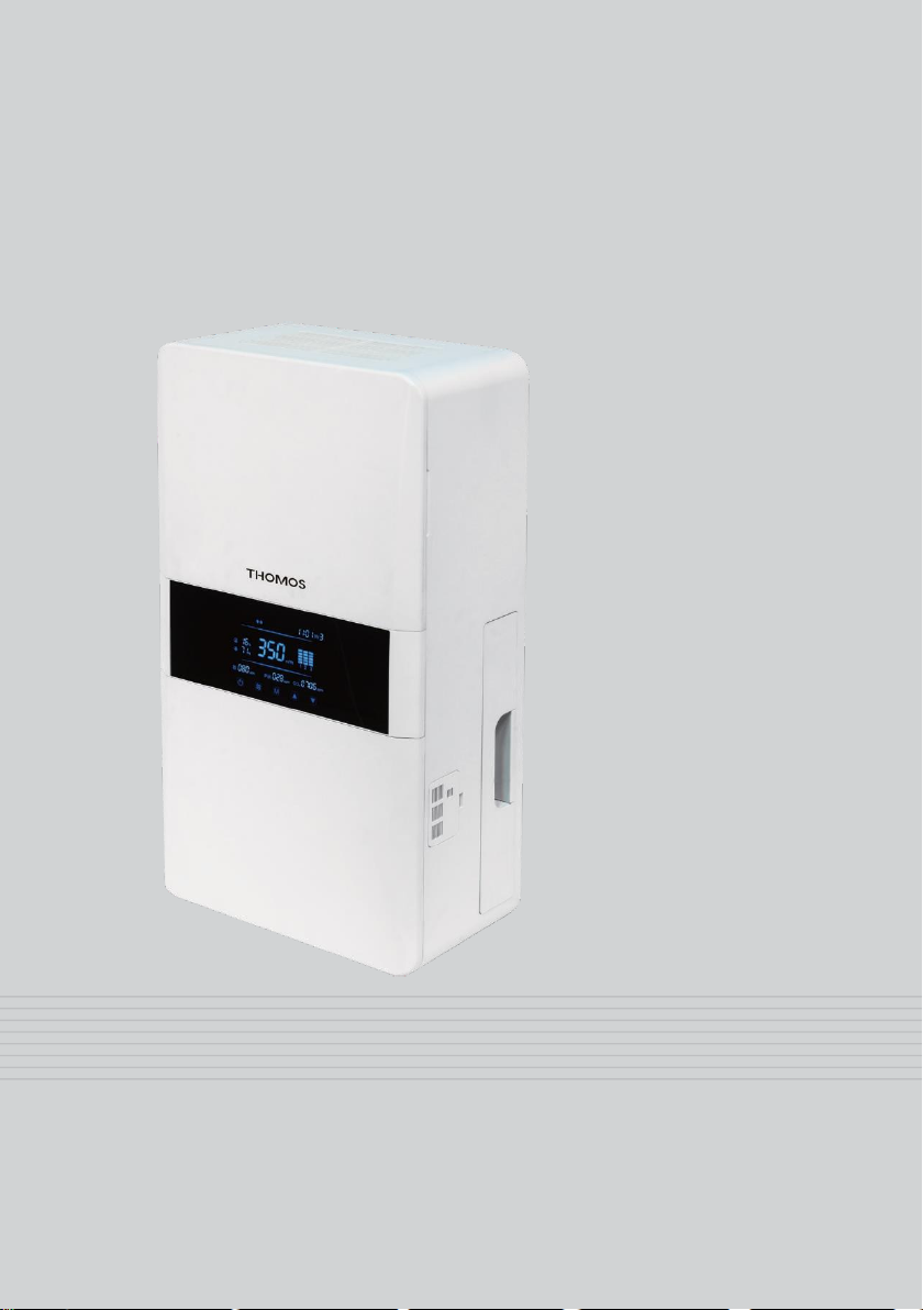
PAC-350WM
Installation, operation & maintenance instructions
DO NOT THROW AWAY

IMPORTANT SAFETY INFORMATION –PLEASE READ THESE INSTRUCTIONS
CAREFULLY PRIOR TO COMMENCING INSTALLATION
Responsibility for the correct and safe installation rests with the installer.
Read through the full manual prior to installation.
Make sure there is sufficient space to install the unit for effective operation and to
ensure access for maintenance and servicing.
Take care to ensure the external air intake is positioned so that it is not near
combustion gases, boiler vents or other open flues.
Any electrical work must be done by a qualified and licensed electrician.
If the power cable is damaged, do not use the unit and contact the supplier.
Use at the rated voltage.
Install the unit to a sufficiently strong wall surface with appropriate anchors for the
weight.
Do not use is excessively hot temperatures (above 40C) or excessively cold
environments (less than -20C).
In areas prone to strong winds, install a 90-degree bend on the wall termination kit if
the prevailing winds are liable to blow directly at the external intake or extract louvre.
This appliance is not intended for use by persons (including children) with reduced
physical, sensory or mental capabilities, or lack of experience and knowledge, unless
they have been given supervision or instruction concerning use of the appliance by a
person responsible for their safety.
Young children should be supervised to ensure they do not play with the appliance.
Turn the unit off whilst undertaking any building renovations.
Before doing any maintenance work, including changing or cleaning filters, the unit
must be isolated from the electrical supply.
Introduction
The PAC-350WM is a wall mounted heat recovery ventilation unit designed for use
within small commercial environments. It provides fresh air for building occupants (as
determined by building regulations) in addition to having the boost functionality to
provide a purge ventilation cycle when required.
The supply and extract fans within the unit simultaneously supply fresh air and extract
stale air whilst transferring the heat from the dirty air to the fresh air intake airflow.
To minimise fallow time, the unit will provide 10 air changes for a room with a volume
of 35m3 or less. The room volume is simply calculated by multiplying the width of the
room by the length of the room by the height of the room (in metres).
The unit is to be installed directly on an external wall. 2 holes will need to be drilled
through the wall with ducting pushed through the holes from outside and an air
termination device installed externally to both the supply and extract duct.
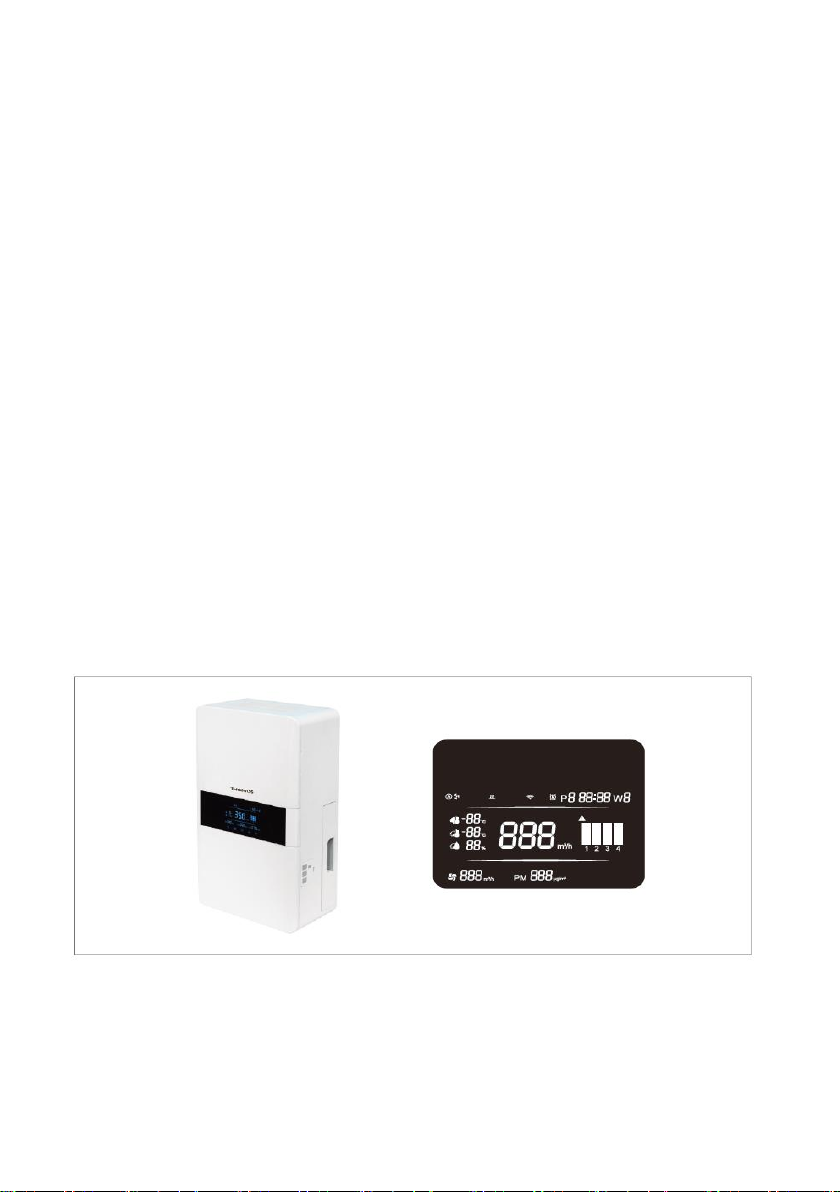
The unit has an integral LCD touch screen controller which provides all functionality
and shows the internal air conditions as the unit has inbuilt particle, CO2 and humidity
sensors.
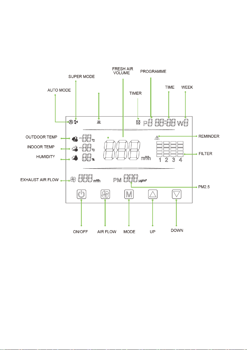
Control panel layout

Unit diagram
Key
1 Supply air discharge
2 LCD touch screen control panel
3 Supply air filter housing (primary and secondary air filters)
4 CO2, humidity, PM2.5 & temperature sensors
5 Extract air intake
6 Supply air blank panel for changing the filter handing
7 Supply air discharge filter
8 Extract air filter
9 Heat exchange unit
Unit dimensions
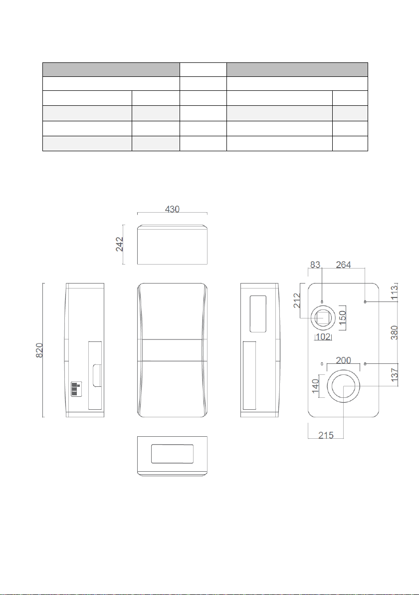
Dimensions
Duct sizes
Height –mm
820
Supply air –mm
160
Depth –mm
230
Exhaust air –mm
120
Width –mm
430
Weight –kg
21
Installation
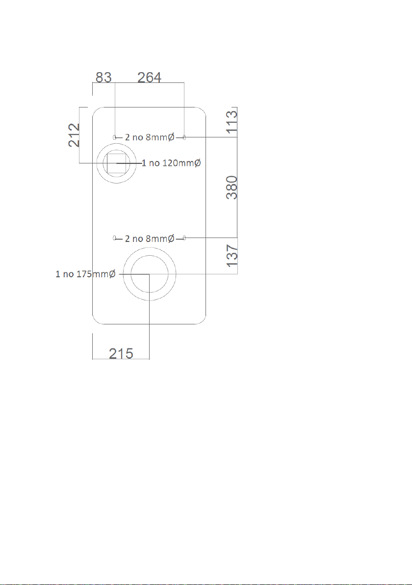
Use the supplied template to mark and make the holes in the external wall for the
ducts from the rear of the unit.
Use the template to make the 4 no holes for the fixing screws for the unit.
Ensure the screws and fixings have the strength to support the weightof the unit and
check that the wall is strong enough to hang the unit.
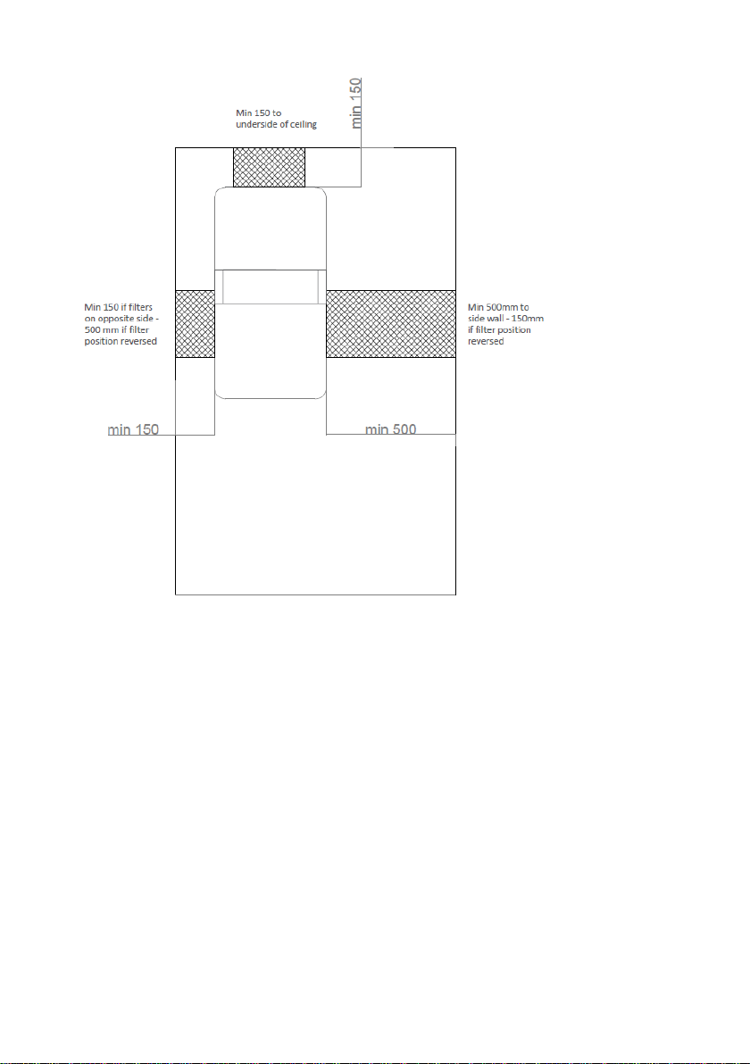
Unit setting out
Minimum clearance for installing the unit are to be as per the diagram above
Changing the filter access
The filter access can swap sides if maintenance access is a problem with the filter
housing in its default factory location.
Remove the supply air filter by sliding out the filter housing on the side of the unit.
Remove the blanking panel on the LHS of the unit and slide in the filter housing
ensuring the same orientation of the filter box (ie the airside filter on the external
facade side of the unit). Put the blanking plate on the RHS.
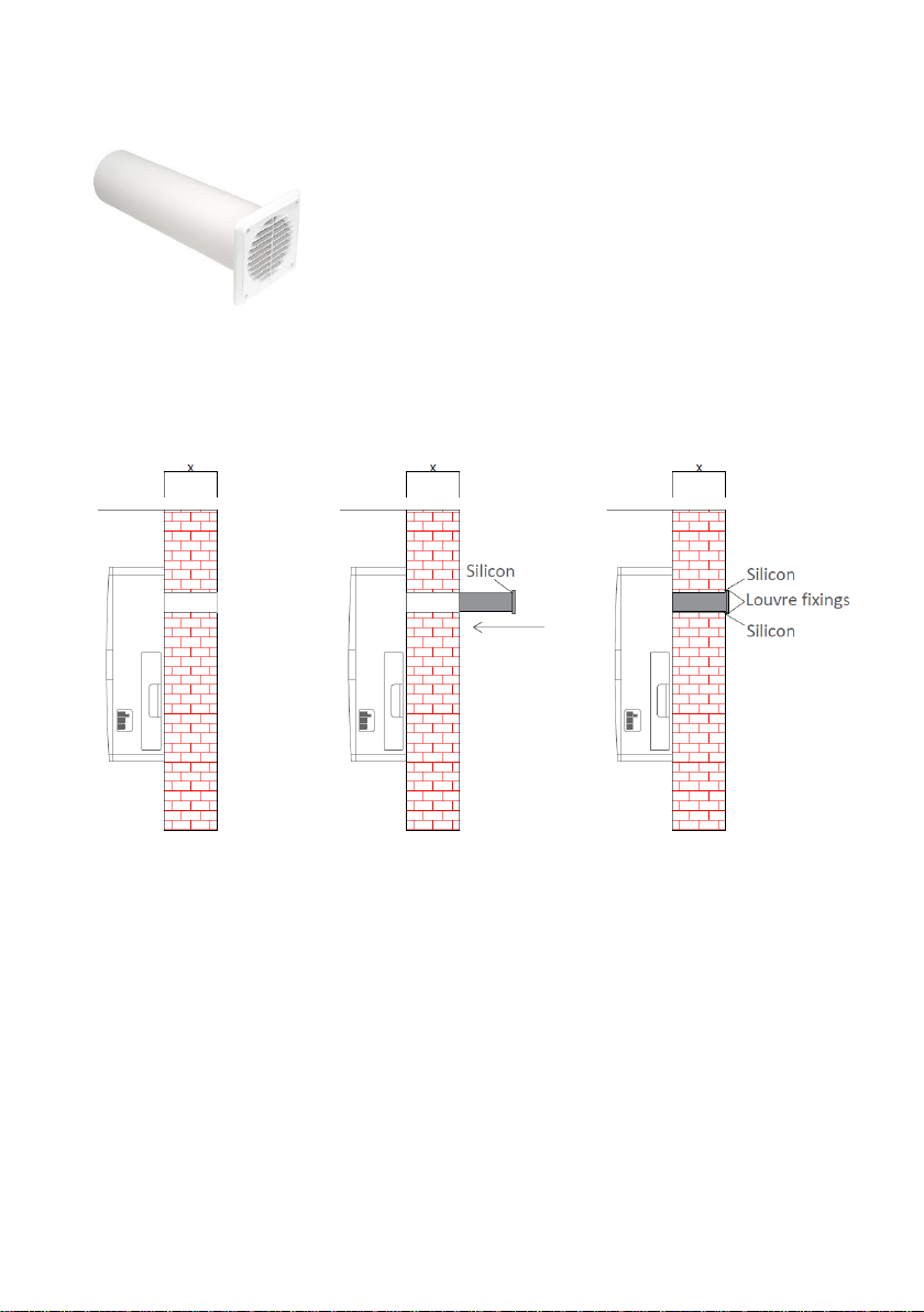
Installation of duct wall termination kit:
Supply air duct: 150 width with external louvre
Extract air duct: 125 width with external louvre
Measure the width of the wall through the hole formed for either duct:
Cut the plastic ducts (supply & extract) to size (length x) with a hacksaw.
Fix the external louvres to the plastic ducts with silicon.
Push each duct and louvre through the hole.
Secure the louvres with 4 no screws and appropriate anchors.
Seal around the louvres with an external sealant.
Table of contents
Popular Fan manuals by other brands

ELTA FANS
ELTA FANS H03VV-F installation guide

Hunter
Hunter 20714 Owner's guide and installation manual

Emerson
Emerson CARRERA VERANDA CF542ORB00 owner's manual

Hunter
Hunter Caraway Owner's guide and installation manual

Panasonic
Panasonic FV-15NLFS1 Service manual

Kompernass
Kompernass KH 1150 operating instructions


