IMPORTANT INFORMATION
ELECTRICIANS MUST READ PRIOR TO INSTALLATION
1. Distributor and installer details and purchase receipts are essential for on-site warranty claims
and must be presented to repair personnel, make sure you record your details in the Fan Owner
Warranty and Operations Manual.
2. Fans and fixed wiring products must only be installed by persons who are appropriately licensed
by the applicable State regulatory body. Therefore, to protect our repair personnel, on-site
warranty claims will not be accepted if products have been installed by unlicensed persons.
3. Damage caused by incorrect installation, force-majeure, electrical surges, lightning, power grid
fluctuations, water or by connection to alternative power supply sources (such as solar inverters,
etc.) is not eligible for warranty repair.
4. Blades must be replaced only as a complete set. Blades are supplied only as a pre-balanced set
and the replacement of individual blades may void the warranty by causing mechanical
damage to the motor, excessive noise or premature wear.
5. When products are installed in a location requiring special access equipment (such as
scaffolding or scissor lifts, etc) the cost of providing, installing and operating special access
equipment must be borne by the site owner.
For safety, and to protect your customers warranty, the following must be taken into
account when installing and operating the product (s):
IF THERE ARE ANY PROBLEMS WITH THE PRODUCT AT TIME OF
INSTALLATION THE INSTALLER MUST CONTACT THE WARRANTY
HOT LINE NUMBER 1300 360 280. BEFORE LEAVING THE JOB
SITE. PLEASE DO NOT REMOVE THE FAN FROM THE CEILING
ONCE INSTALLED UNLESS INSTRUCTED TO DO SO.
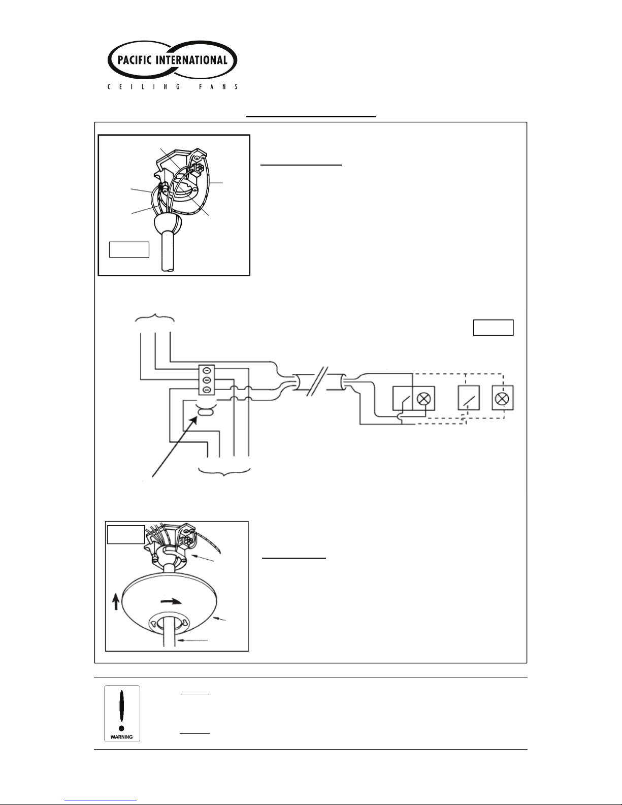
(a) DO NOT USE SOLID-STATE WALL CONTROLLERS. Neither leading nor lagging edge
controllers will give satisfactory performance. Wall controls must only be types approved
for use by Pacific International Ceiling Fans.
(b) The fan, light and bracket must be earthed.
(c) Fan and light must be run from the same phase and preferably the same final circuit.
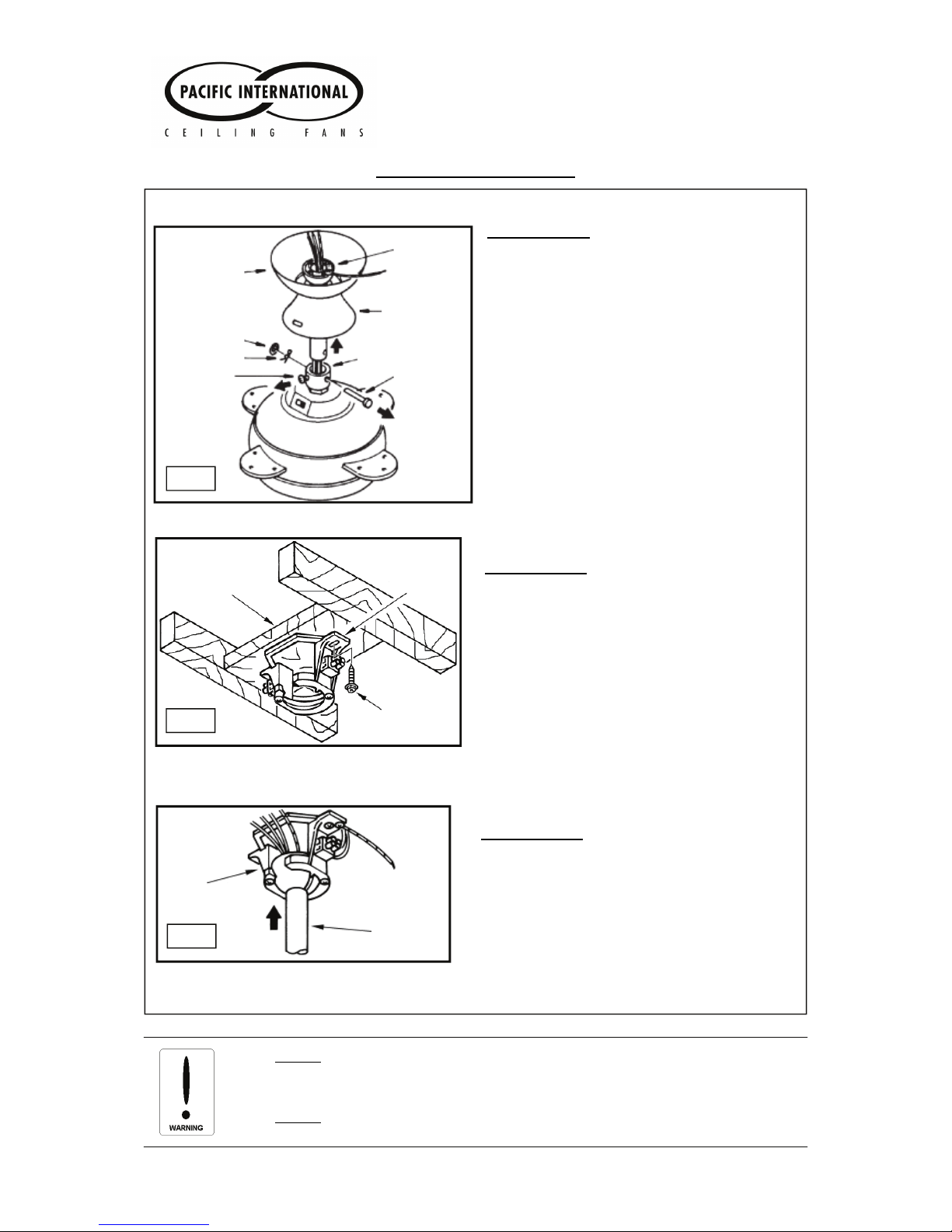
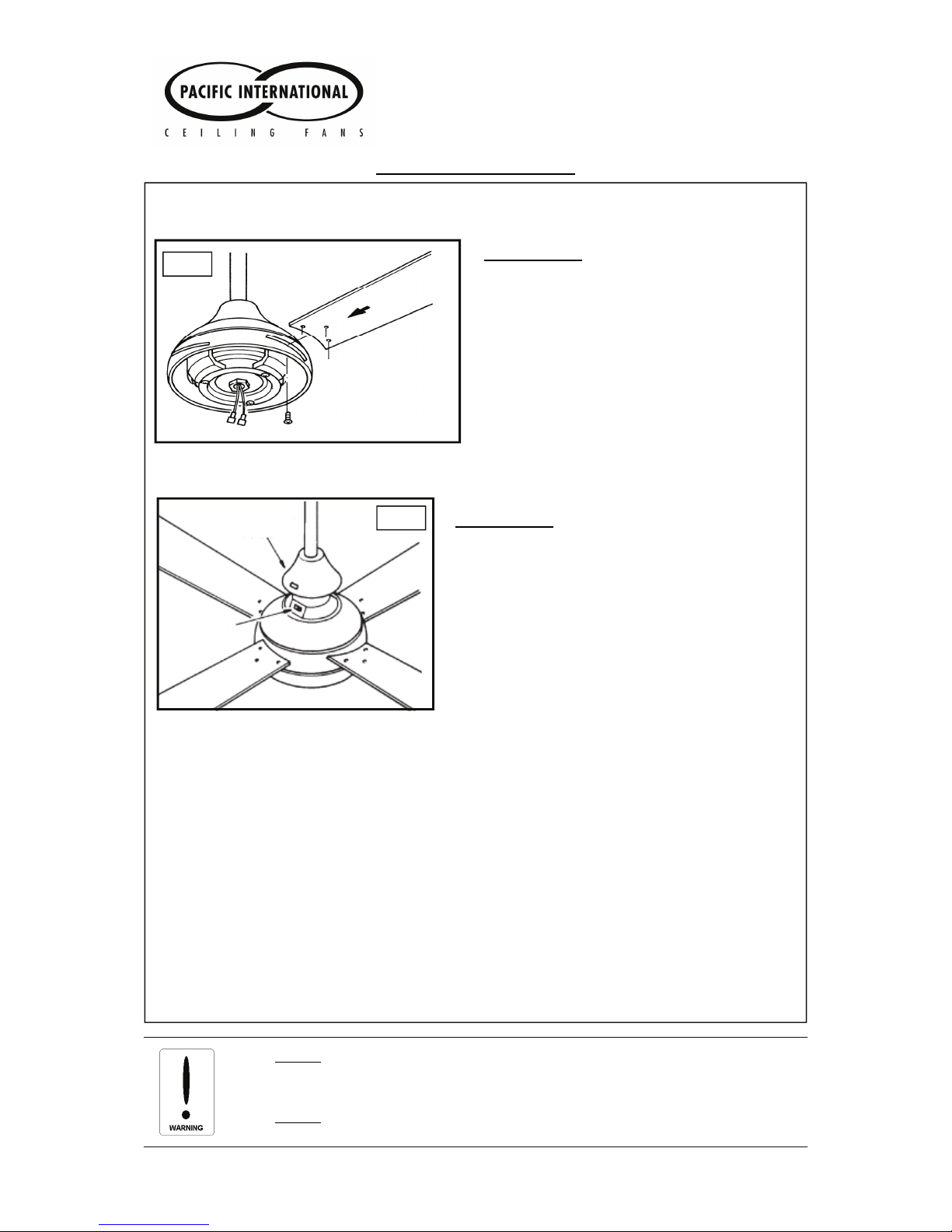
(d) Mounting bracket must be firmly screwed to a solid structure such as a concrete ceiling,
steel structure or timber framing. If additional bracing is added it must be firmly secured to
the rafters and not left floating on the ceiling. Special mounts, such as T-hooks, are
available for certain types of installation.
(e) After installation, fan blades must be at least 2.1 m (7 feet) above floor level.
(f) The use of these products by children and the infirm must be under supervision.
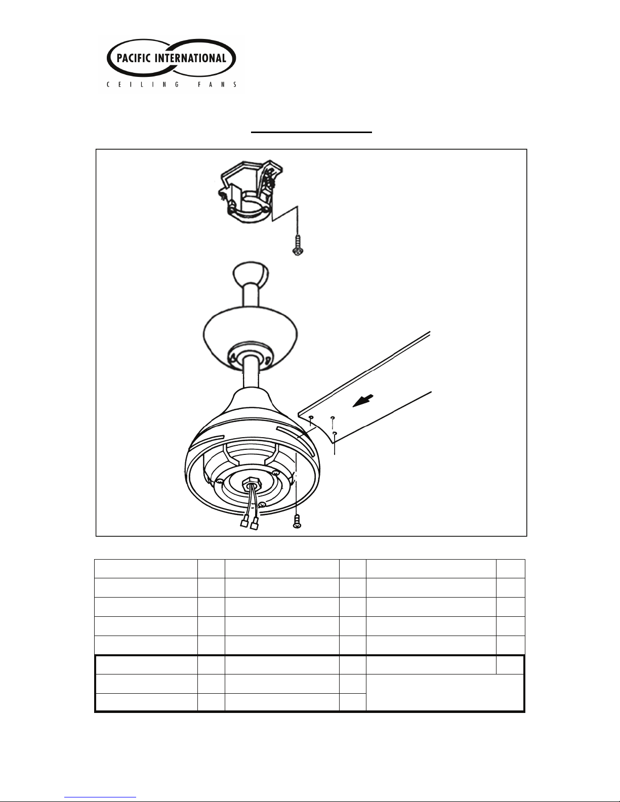
Electrician Installation Manual
EM-E Ceiling Fan
2