manuals.online logo
Brands
  1. Home
  2. •
  3. Brands
  4. •
  5. Panasonic
  6. •
  7. Microcassette Recorder
  8. •
  9. Panasonic RQ-J20X User manual

Panasonic RQ-J20X User manual

ORDER
NO.
ARD82080186C2-09
Service
Manual
Mini
Cassette
World's
First
dbx
-Equipped
RQ-J2
OX
Stereo
Cassette
Player
(Dark
Gray)
This
is
the
Service
Manual
for
the
following
areas.
sage
aaa
For
all
European
areas.
RQ-2720
MECHANISM
SERIES
Specifications
Power
requirements:
AC;
with
optional
AC
adaptor
RP-31
Battery;
3V
(two
R6
size
dry
batteries)
Rechargeable
battery;
with
optional
rechargeable
battery
pack
RP-009
Track
system:
4-track
2-channel
stereo
playback
with
included
stereo
headphones
Tape
speed:
4.8cm/s
Dynamic
range:
More
than
97
dB
(at
1kHz),
with
dbx
in
Signal-to-noise
ratio:
dbx
in;
81dB
dbx
out;
56dB
(A
weighted,
3%
THD
at
1
kHz)
Fast
forward
and
rewind
time:
Approx.
120
seconds
with
C-60
cassette
tape
Input:
DC
in;
3V
Output:
Headphones;
output
level
630
mV
(162)/CH
Head:
1
LH
head
for
stereo
playback
Dimensions:
88.0mm(W)
X
138.0mm(H)
x
27.1mm(D)
Weight:
340
g,
without
batteries
Specifications
are
subject
to
change
without
notice
*
The
term
dbx
is
a
registered
trademark
of
dbx
Inc.
Pas)
a *
5
Panasonic
Metab
Sects
hatyee
te
nL
OLN
10>
CONTENTS
ITEM
PAGE
ITEM
PAGE
LOCATION
OF
CONTROLS
AND
COMPONENTS
:--
2
SCHEMATIC
DIAGRAM
cvrresserrereeeceeeceeeectete
reece
ones
9
DISASSEMBLY
INSTRUCTIONS
-=-+++-++*+--+++-+++++<-
2
CIRCUIT
BOARDS
AND
WIRING
CHIP
PARTS
REPAIR
PROCEDURE
<-*:-:***eeeeeee+*
el
CONNEGTION
DIAGRAM
cjsecssessesseeonsesmrsce
mn
ccene
11
MEASUREMENT
AND
ADJUSTMENT
MECHANICAL
PARTS
LOCATION
c-r-rerereereeeer
teres
15
MAE
TOUS
ese
ee
toc
cSt
oneteiacdansuweievesseuenasents
4
SPRING
LOCATION
Si
Gecteee-essssicstansessssenenacsvviees
17
ELECTRICAL
PARTS
LOCATION
srrrereeeeeeeeeeteeeeees
6
CABINET
PARTS
LOCATION
2i-ce0tGeiersdectectasccss
18
BOC
DING
RING
oats
ete
neccarsicesnoneonscncsances
7
LOCATION
OF
CONTROLS
AND
COMPONENTS
@
dbx
IN/OUT
switch
@
Playback
button
@®
Fast
forward/cue
button
@®
Rewind/review
button
®
Stop/eject
button
©
Built-in
microphone
@
Battery-check
lamp
@®
Headphones
jack
@
Tape
selector
(Metal
L/Metal
H,
Normal
L/
Normal
H)
Pause/mic
on
switch
@
Volume
control
@
Cassette
compartment
cover
@®
Battery
cover
DC
IN
jack
DISASSEMBLY
INSTRUCTIONS
Bottom
case
y
24assembly
ROQ-J20X
is
I
|
Fr
1
(IW
Epc!
Cassette
_"—_———
_
compartment
T
eat
SO
eel
|
Fig.
4
Procedure
To
remove
——
Remove
——
Shown
in
fig.
——
.
-
Battery
cover
1
+
2
screws
1
+
3
black
screws
2
-
As
shown
in
fig.
1,
push
the
claw
in
the
direction
of
arrow
©,
then
lift
bottom
case
assembly
in
the
direction
of
arrow
@).
Bottom
case
assembly
+
2
screws
*
1
red
screw
-
First,
press
the
stop/eject
button,
and
open
the
cassette
compartment
cover.
Main
case
assembly
Press
the
playback
button,
and
push
the
mechanical
assembly
up
in
the
direction
of
arrow
@)
while
pulling
portion
@)
in
the
direction
of
arrow
@),
as
shown
in
Fig.
3.
Then,
the
main
case
assembly
can
be
removed.
>
1
red
screw
+
2
screws
+
2
black
screws
-
Unsolder
the
soldered
portion
of
the
brush
holder
assembly
CHIP
PARTS
REPAIR
PROCEDURE
(transistor,
diode,
resistor
and
capacitor,
etc.)
Main
circuit
board
and
motor
governor
circuit
board
A.
Removal
1.
Remove
all
solder
from
both
ends
of
chip
using
a
solder
sucker
(RP8062)
or
desoldering
wick.
Tweezers
2.
While
the
chip
is
hot
remove
it
by
turning
with
tweezers,
as
shown
in
fig.
1.
*
Make
sure
that
the
unit
is
turned
OFF
when
checking
the
resistance
and
polarity
of
a
chip.
Soldering
iron
Unsolder
B.
Mounting
Place
solder
on
the
foil
chip
mounting,
and
solder
the
chip
while
applying
Soldering
iron
the
soldering
iron
in
the
direction
of
the
arrow,
as
shown
in
the
diagram
y
&
(point
must
(fig.
2).
be
clean)
Fig.
2
Solder
C.
Precautions
in
mounting
the
chip
1.
Do
not
heat
the
chip
beyond
3
seconds.
2.
Do
not
rub the
electrode.
3.
Use
tweezers
to
prevent
any
damage
to
the
surface.
4.
It
is
recommended
that
a
pencil-type
soldering
iron
be
used.
5.
Maintain
temperature
control
under
260°C
(500°F)
when
soldering.
*
Chip
resistance
(of
not
more
than
100Q)
may
vary
greatly
with
the
direction
of
mounting;
therefore,
mount
the
white
side
on
the
pattern
side.
6.
Do
not
re-use
the
tantalum
capacitors
or
ceramic
capacitors
after
removal
(use
new
components).
7.
Do
not
subject
the
components
(chips)
to
excessive
stress.
ok,
3
—
RO-J20X
MEASUREMENT
AND
ADJUSTMENT
METHODS
Condition:
Equipment:
*
VTVM
*
Stereo
M3
Tape
speed
adjustment
Condition:
Equipment:
*
Test
tape-
*
Stereo
M3
adjustment
Condition:
Equipment:
*
VTVM
*
Test
tape
-
Head
azimuth
adjustment
*
Playback
mode
*
Test
tape
(azimuth)
*
Resistor
(16Q)
*
Playback
mode
*
Digital
electronic
counter
or
frequency
counter
++
QZZCWAT
*
Resistor
(16Q)
Attack
recovery
time
*
Playback
mode
«+
QZZCFM
NOTES:
@
Make
sure
head
is
clean.
@
Make
sure
capstan
and
pressure
roller
are
clean.
e
Judgeable
room
temperature:
20£5°C
(68+9°F)
ITEM
MEASUREMENT
&
ADJUSTMENT
L-CH/R-CH
output
balance
adjustment
1.
Make
connections
as
shown
in
fig.
1
and
2.
2.
Playback
the
8
kHz
signal
from
the
test
tape
(QZZCFM).
Adjust
screw
(B)
in
fig.
3
for
maximum
output
L-CH
and
R-CH
levels.
When
the
output
levels
of
L-CH
and
R-CH
are
not
at
maximum
at
the
same
time,
readjust
as
follows.
Turn
the
screw
shown
in
fig.
3
to
find
angles
A
and
C
(points
where
peak
output
levels
for
left
and
right
channels
are
obtained).
Then,
locate
the
angle
B
between
angles
A
and
C,
i.e.,
a
point
where
L-CH
and
R-CH
output
levels
come
together
at
maximum
(Refer
to
figs.
3
and
4).
*
Oscilloscope
+++
QZZCFM
plug
L-CH/R-CH
phase
adjustment
4.
Make
connections
as
shown
in
fig.
2
and
5.
and
a
waveform
as
illustrated
in
fig.
6
is
obtained
on
L-CH
peak
level
R-CH
peak
level
accuracy
Tape
speed
accuracy
1.
Test
equipment
connection
is
shown
in
fig.
2
and
7.
2,
playback
signal
to
frequency
counter.
3.
Take
measurement
at
middle
section
of
test
tape.
4.
Measure
this
frequency.
5
f—3,000
3,000
where,
f
=measured
value
“e
Tape
speed
accuracy
=
Standard
value:
+2.5%
.
If
measured
value
is
not
within
standard,
adjust
tape
location),
so
that
frequency
becomes
3,000
Hz.
Test
equipment
connection
is
shown
in
fig.
8.
Set
dbx
switch
to
IN.
Playback
the
test
tape
(QZZCFM:
315Hz/0
dB).
Read
voltage
on
VTVM.
PWN
Reference
value:
15+0.5mvV
Playback
head
UNIT
Dummy
\y
2
load
(16.2)
iB
Sees
-
r
S
eee
Insert
A
Dummy
i i
load
(160)
Shield
wire’
Black
R-CH
5.
Playback
the
8kHz
signal
from
the
test
tape
(QZZCFM).
(B)
shown
in
fig.
3
so
that
pointers
of
the
two
VTVMs
swing
to
maximum
Playback
test
tape
(QZZCWAT
3,000Hz),
and
supply
.
On
the
basis
of
3,000Hz,
determine
value
by
following
formula:
X
100
(%)
e
Volume
control:
Maximum
©
Tape
select
switch:
Normal
(Hi)
@
Pause
switch:
OFF
©
dbx
switch:
OUT
Headphones
jack
Es
ee
ee
16
Playback
mode
Fig.
1
a
“VIVM
Oseilloscope
Shield
wire
L-CH
Fig.
2
c
Playback
head
\
Adjust
screw
A
Screw
(B)
Fig.
3
the
oscilloscope.
jack
Playback
mode
Digital
electronic
counter
Fig.
7
speed
adjustment
VR
(shown
in
electrical
parts
ITEM
MEASUREMENT
&
ADJUSTMENT
Level
difference
adjustment
for
pre-amp
and
dbx
IC
(AN6291)
1.
Test
equipment
connection
is
shown
in
fig.
9.
2.
Set
volume
control
(VR2)
to
maximum
and
dbx
switch
to
IN.
3.
Playback
the
test
tape
(QZZCFM:
315Hz/O
dB),
and
using
VTVM
measure
the
output
level.
Channel
balance
adjustment
Condition:
*
Playback
mode
Equipment:
+
VTVM
*
Test
tape
---
VR2-1
(L-CH)
—O-
Ground
—_
VR2-2
QZZCFM
<©—
<9
(R-CH)
"y
.
Perform
measurement
for
both
channels.
.
Check
that
the
measured
values
for
both
channels
are
in
a
range
of
22.4mV
(—33dB)
to
31.6mV
(—30<B),
and
that
the
level
difference
between
channels
is
3
dB
or
:
less.
Fig.
9
.
lf
the
measured
values
do
not
meet
the
above
requirements,
the
following
adjustment
is
required.
The
playback
output
and
level
difference
between
channels
of
the
RQ-J20X
can
be
adjusted
by
control-
ling
the
playback
gain
of
the
pre-amp.
Procedure:
L-CH
and
R-CH
playback
gains
change
as
shown
in
table
1
according
to
open/short
circuit
at
connection
points
®),
©,
©,
©,
©
and
@
on
the
main
circuit
board
(fig.
10).
For
level
difference
adjustment,
open
or
short
the
connection
points
by
soldering
so
that
the
output
level
difference
between
L-CH
and
R-CH
is
minimal.
Connection
point
Connection
point
©
Connection
point
©
Open
Short
Open
Short
—_—_}—__
Open
Open
Short
Short
Short
Open
Open
Open
R-CH
output
level
2dB
up
4dB
up
6
dB
up
9dB
up
Connection
point
©
Open
SEER
Connection
point
©
Connection
point
@
L-CH
output
level
Open
Short
Open
Short
Open
Short
Short
Short
Open
Open
Open
2
dB
up
4dB
up
6
dB
up
9dB
up
Table
1
we
(Se
GD
omc
point
©
R
|
oe
re
we
Se
Connection
point
©.
Connection
point
©)
Main
circuit
board
(back
side)
Connection
point
@)
Connection
point
©
Connection
point
Connection
point
©
Fig.
10
Level
difference
adjustment
for
headphones-amp
.
Test
equipment
connection
is
shown
in
fig.
1
and
2.
.
Set
volume
control
to
5,
tape
selection
switch
to
normal
(Hi)
and
dbx
switch
to
OUT.
.
Playback
frequency
response
test
tape
(QZZCFM),
and
using
VTVM
measure
the
output
level
at
headphones
jack.
.
Make
measurement
for
both
channels.
.
Check
output
if
level
difference
between
L-CH
and
R-CH
is
within
2
dB.
L-CH
output
level
—
R-CH
output
level
=
+2dB
If
the
measurement
value
do
not
meet
the
standard
value
range,
adjust
as
described
below.
.
L+CH
and
R-CH
playback
output
balance
adjustment
of
RQ-J20X
is
done
by
adjusting
the
gain
of
the
L-CH
and
R-CH
headphones
amplifier.
Procedure:
L-CH
and
R-CH
output
level
changes
as
shown
in
table
2
by
opening
or
shorting
connection
points
@)
and
©
on
the
main
circuit
board
(fig.
10)
by
soldering.
So
open
or
short
the
connection
points
so
that
the
output
level
difference
between
L-CH
and
R-CH
is
minimized.
Channel
balance
adjustment
Condition:
*
Playback
mode
Equipment:
*
VTVM
*
Oscilloscope
*
Test
tape
---
QZZCFM
*
Stereo
M3
plug
*
Resistor
(16Q)
Connection
point
@
R-CH
output
level
Connection
point
@)
L-CH
output
level
Open
Up
Open
Up
t t
Short
Short
Table
2
Confirmation
of
dbx
decode
effect
Condition:
*
Playback
mode
Equipment:
*VTVM
*
ATT
*
AF
oscillator
*
Stereo
M3
plug
.
Supply
315
Hz
signal
from
AF
oscillator
through
4
estilator
.
Remove
three
lead
wires
of
head
by
desoldering.
.
Test
equipment
connection
is
shown
in
fig.
2
and
11.
.
Set
dbx
switch
to
IN.
.
Load
a
cassette
tape
(to
defeat
auto-stop
function),
and
set
the
unit
to
playback
mode.
=
ATT
(for
—78dB
attenuation)
to
head
lead
wire
terminal
(on
FPC)
(for
both
channels)
as
shown
Head
lead
wire
terminal
Headphones
jack
Playback
mode
*
Resistor
(16.Q)
in
fig.
12.
control
(VR2).
signals
are
inputted.
.
At
this
time,
measure
output
level,
and
adjust
measured
value
to
50
mV
by
adjusting
volume
.
Next,
attenuate
315
Hz
signal
by
—66dB
and
—86
dB,
and
measure
output
levels
when
these
.
Perform
measurement
for
both
channels.
.
Check
that
the
measured
values
meet
the
requirements
in
the
dbx
decode
eftect
table.
dbx
decode
effect
table
Input
signal
|
Measured
value
~76dB
(315Hz)
|
OdB
(50
mV)
—66
dB
(315Hz)
|
+2043
dB
(500mvV)
—86
dB
(315Hz)
ELECTRICAL
PARTS
LOCATION
REPLACEMENT
PARTS
LIST
Part
Name
&
Description
ELECTRICAL
PARTS
E1
QWY4142Y
Playback
Head
E2
QES1533
Brush
Holder
Assembly
E3
WM034BZ103
Condenser
Microphone
E4
QKJ0502
Microphone
Holder
E5
QKJ0501
Holder
E6
QGT1562
Switch
Knob
(for
Pause)
E7
QYTO639W
Volume
Knob
E8
QQC1735
Shelter
EQ
QTS1590
Shield
Plate
E
10
QBHO0081
Insulating
Sheet
Et
QTD1258
Lug
Terminal
E
12
XQN16+A3FZ
Screw
@1.6x3
E13
XQN16
+
A35FR
Screw
@1.6x3.5
E14
XQN16+C4FY
Screw
@1.6x4
E15
XTNQI6C4FFR
Screw
@1.6x4
E16
QHQ1320
Step
Screw
E17
-
QBH0180
Protection
Sheet
E
18
QYT0654
Switch
Knob
(for
dbx)
E19
XTNQ16C28F
Tapping
Screw
@1.6x2.8
E
20
XTNQ16A3F
Screw
@1.6x3
E21
QTW1242
Insulating
Sheet
—20+3dB
(5mV)
E20
E5
£19
6002
6002
Main
circuit
board
(back
side)
Fig.
12
Ett
‘E13
E18
E12
E15
E9
EA,
E16
Tape
speed
adjustment
VR
BLOCK
DIAGRAM
B+ B+
(2.8V)
(28V)
DE
EMPHASIS
(dbx)
$62
S71
i
=
z
Output
level
O
contro!
CR
BETWEES
CR
NETWORK
:
i
VR2-1
ve) v~)
ad
=
=>
==
ON:
|
Vee
RMSIN
[TIMING
|CCAIN
|caP1
cAP2
v
ouT
OFF
I
TIME
ENCODE
RMS
‘aA
4
DETECTOR
CONNECTION
POINTS
C)
|
MUTING
(FORCHANNEL
BALANCE
—
(iii
E
Of
Le
EH
HH
(FOR
P.B
ADJUSTMENT)
=
_
Logic
out)
a7,8
PLAYBACK
HEAD
P.BEQ
.
2
aS
i
RMS
OP
AMP
til
$7-3
DETECTOR
ny
6
He
{nF
I
in
‘
:
bid
=
d
OO)
OOOO
OO)
tt
@®
CCA
IN
VOUT
‘ON-
NA
DECODE
|
|
vAt
~~
OFF
i
rtot-ta
Q
O-Ftime
$
~
(iil
ei
bh
INSTA\
iea@e6)
ode
fas
it
Lt.
-—
BS
ADJUST-
CR
NETWORK
ORK
:
CRINETHORKC
\
og
: |
vR2-2
=
MENT
VR
v-0
v=
|
Output
level
CONNECTION
POINTS
Jey
Control
(FOR
CHANNEL
BALANCE
ADJUSTMENT)
De
EMPHASIS
(Gon)
;
|
1
=
ly
4
+
———
|
(2.8V)
[=e
Sa
ul
i
eS
SS
te
i
sw
7
D
!
ELECTRET
CONDENSER
CONNECTION
POINT
(H)
MICROPHONE
i]
[J]
a
Qi0
+
gies
MICROPHONE
MUTING
MUTING
(FOR
P.B
OUT)
Qn
POWER
ON/OFF
(FOR
MOTOR)
J
MOTOR
GOVERNOR
CIRCUIT
MOTOR
WITH
MOTOR
GOVERNOR
CIRCUIT
BOARD
\C3
AN6257
AUTO
STOP
CONTROL
(FOR
CHANNEL
BALANCE
ADJUSTMENT)
“AN
WD
POWER
STAGE
1C2
BAF5204
POWER
AMP
HEADPHONES
JACK
fae
Ns
W\—{1DConnecrion
Point
(1)
(FOR
CHANNEL
BALANCE
ADJUSTMENT)
O
OC
IN
JACK
O
Q——=!
“ake
mel
BATTERY
(3V)
=
=
Ce
ee
ro
7
NOTES:
ROTARY
SWITCH
(ROTATING
DETECTION).
PLAYBACK
SWITCH
(shown
in
OFF
position).
.-FAST
FORWARD/REWIND
SWITCH
(shown
in
OFF
position).
..POWER
ON/OFF
SWITCH
(shown
in
OFF
position).
..
TAPE
SELECT
SWITCH
((1)
Normal
Hi,
(2)
Normal
Low:
Metal
Hi,
(3)
Metal
Low).
..dbx
IN/OUT
SWITCH
(shown
in
IN
position:
(4)
OUT,
(6)
IN).
PAUSE
&
MIC
SWITCH
(shown
in
OFF
position).
(
==>)
this
arrow
indicates
the
flow
of
the
playback
signal.
(
---B
)
this
arrow
indicates
the
flow
of
the
control
signal.
—-7-—
S2
$3.
S4.
$5.
S6.
ROQ-J20X
NOTES:
RESISTORS
CAPACITORS
ERD...Carbon
EGBA:
<<
i.33
Ceramic
ECEON
ERG...Metal-oxide
ECGD......
Ceramic
ECOS
2...
Polystyrene
ERS
...Metal-oxide
ECKD......Ceramic
ECSO......Tantalum
ERO...Metal-film
ECCBe..03.
Ceramic
QCS
sis.
Tantalum
ERX
...Metal-film
EGED
5.22
Ceramic
CHIP
RESISTORS
ERQ...Fuse
type
metallic
ECQM......Polyester
film
RRD
......
Carbon
ERC...Solid
ECOQE
......Polyester
film
CHIP
CAPACITORS
ERF
...Cement
ECOQF
......Polypropylene
QCUD......
Ceramic
ECEO......Electrolytic
ECSE
......Tantalum
REPLACEMENT
PARTS
LIST
reine
[penne
|
woe
|
Part
No.
Ref
No.
...Non
polar
electrolytic
Part
No.
TERMINATIONS
RESISTORS
|
VARIABLE
RESISTORS
j
C55
ECEA1CK100
fa?
a
arama
(011.
ECEAOGK221
R1,2
RRD18XJ273
VR
1
QVM42TB2228A
|
C
57
ECEAOGK470
R3,
4
RRD18XJ564
VR2
QVBL1HC03A24
|
C58
ECEA0GK221
R5,6
RRD18XJ153
©
59,60
ECEAQJK220
R7,8
RRD18XJ102
CAPACITORS
cé1
ECEA1CK100
RQ,
10
RRD18XJ471
=...
C62
ECEAQJV471
R11,12
RRD18XJ271
Cae
ECSF1VM474
C63
ECEA0GK221
R13,14
RRD18XJ121
C3,
4
QCUT1H102MRL
|
C
64
QCUT1H102MRL
A
R15,16
RRD18XJ124
C5,6
QCUT1H471MRL|
C
65
QCUT1H332MRL
|
Anode
O—Pt—O
Cathode
R17,18
RRD18XJ564
C7,8
ECEA1HKR47
R19,20
RRD18XJ332
C9,
10
QCUX1E333KRX
TRANSISTORS
D4
R21,22
RRD18XJ152
C
11,12
ECEA1HKR33
dad
Mee
R
23,24
RRD18XJ472
C13
ECSF1CM474
Q
1,
2, 3,
4,
5,
6,
7,
8,
10
Chip
Resistor
R25,26
RRD18XJ123
C14
ECEA1HKR47
2802412
R
27,28
RRD18XJ560
C
15,16
QCUX1E333JRX
|
Q11
2SA1037
Black
R
29,30
RRD18XJ561
C
17,18
ECEA16z10
Q
12
2802412
R31,32
RRD18XJ102
C
19,20
ECEAOGK470
Q13
2SA1037
1
|
R
33,34
RRD18XJ103
C
21,22
QCUTIH472JRL
|
Q
14
2802412
R35,
36
©
RRD18XJ163
C
23,24
QCUTIE223JRL
|
Q
15,16
2SA1037
—\M—
R
37,38
RRDI8XJ151
C
25,26
ECSFICM474
R
39,40
RRD18XU472
C
27,28
QCUT1H152MRL|
DIODES
&
RECTIFIERS
|
R41,42
RRD18XJ163
C
29,30
ECEAOGK470
ee
Chip
Capacitor
R
43,44
RRD18XJ122
C
31,32
ECEAOGK101
D1
SLR34UR
Ceramic
R45,46
RRD18XJ121
©
33,34.
QCUT1H103MRL}
D
2,3
DAN202TB
Bown
R
47,48
RRD18XJ680
C
35,36
QCUT1H102MRL|
D4
SM112
7
>
R
49,50
RRD18XJ332
C
37,38
=
_ECEAOGK470
KZ]
R
53,54
RRD18XJ822
C
39,40
QCUT1H102MRL|
INTEGRATED
CIRCUITS
Qi—8.
10,
|
Q11,
13,
R55,56
RRDI8XK4R7
C50
QCUT1E104ZFL
|
SSS
42.14 15.16
te
R59,60
RRDI8XJ102
C
51,52
ECEAOGK101
IC
1
AN6291S
: ’
R70
RRD18XJ222
C53
ECEA0JK220
IC
2
BAF5204LN
R71
RRD18XJ102
ECEA1HK010
IC
3
AN6257S
R72
RRD18XJ121
SPECIFICATIONS
R73
RRD18XJ104
R74
RRD18XJ820
ame
R75
RRD18XJ273
—
dbx
OUT
—
R76
RRD18XJ153
:
R77
RRD18XJ102
SWITCHES
315H2:
0dB
(30mV)
R78
RRD18XJ391
oe
beeoieas
125Hz:
—0.5+2dB
R79
RRD18XJ820
refer
to
:
+
oT
aed
epee
C
asiceiea
Gis
Playback
frequency
response
|
8kH7z:
0.5+3dB
R81
RRD18XJ331
(Rotary
Detector)
*
Use
test
tape
—
dbx
IN—
R
83
RRD18XJ471
$
2,3,4
QSB0274
Leaf
Switch
++
QZZCFM
R
84
RRD18XJ820
(Play,
FF/REW,
Power
ON/OFF)
315Hz:
OdB
(3mV)
R85
RRD18XJ102
$5,6
QSS2302
Slide
Switch
125Hz:
—1+3dB
R
86
RRD18XJ822
(Tape
Setector,
dbx
IN/OUT)
Zz
-—
R
87
RRD18XK330
S7
Qss4214
Slide
Switch
8kHz:
9+5dB
R
88
RRD18XJ123
(Pause/Mic
ON)
R89
RRD18XJ104
R
90
RRD18XJ682
JACKS
Playback
gain
R91
RRD18XJ102
R
92
RRD18XJ222
QJA0173
M3
Jack
*
Use
test
tape
Greater
than
0.64
V
R93
ERD25FJ3R7
QUA0164
DC
IN
Jack
+++
QZZCFM
(315Hz/0dB)
NOTES
.
SSA
cnscaseetraran
Rotary
detection
switch.
Headphones
jack
©:
S25
tarcuawnerarcanie
Playback
ON/OFF
switch
(shown
in
OFF
position).
FF/REW
ON/OFF
switch
(shown
in
OFF
position).
iv
...Power
ON/OFF
switch
(Shown
in
OFF
position).
85245
S5
2
iciicensies
Tape
select
switch
(shown
in
NORMAL
(Hi)
position).
(1)...Normal
(Hi)
(2)...Normal
(Low)
&
Metal
(Hi)
(3)...Metal
(Low)
SOisisnsewtigavicuarsy
dbx
IN/OUT
switch
(shown
in
OUT
position).
$7-1—S7-4
......
PAUSE/MIC
ON/OFF
switch
(shown
in
OFF
position).
METT
semtacattexcinnd
Attack
recovery
time
adjustment
VR.
VR24
252:
cawcirs
Volume
controls.
Connection
points
(B),
(C), (D),
(E),
(F),
(G)...For
channel balance
adjustment
points.
Connection
points
(H),
(I)...For
output
balance
adjustment
points.
Resistance
are
in
ohms
(82),
1/8
watt
unless
specified
otherwise.
1K
=
1,000(2),
1M
=
1,000
K(é2).
Capacity
are
in
microfarads
(uF)
unless
specified
otherwise.
P
=
Pico-farads.
All
voltage
values
shown
in
circuitry
are
under
nosignal
condition
and
volume
control
at
minimum
position.
Unless
otherwise
specified,
voltage
measurement
conditions
are
that
tape
travels
is
at
PLAY,
tape
mode
at
NORMAL
(Hi),
and
dbx
switch
at
OUT.
NO
MARK
.Voltage
at
playback
mode.
(
WY
Sy
shacgons
Voltage
value
at
IN
(dbx
switch)
mode.
(
[=>
)
this
arrow
indicates
the
flow
of
the
playback
signal.
(
E>
)
this
arrow
indicates
the
flow
of
the
talk
signal.
(
tp
)
this
arrow
indicates
the
flow
of
the
playback
and
talk
signal
in
combination.
—s-
Playback
head
162
Playback
mode
Fig.
1
Dummy
Shield
wire
L-CH
load
(16.2)
Dummy
peers
=
White
Insert
Shield
wire
load
(160)
Black
R-CH
Fig.
2
©
Described
in
schematic
diagram
are
two
types
of
numbers;
the
supply
parts
number
and
production
parts
number
for
transistors
and
diodes.
One
type
number
is
used
for
supply
parts
number
and
production
parts
number
which
they
are
identical.
eg.
Q1
2SC2412LN(R,S,E)——Production
parts
number
[28C2412]
Supply
parts
number
¢
The
supply
parts
number
is
described
alone
in
the
replacement
parts
list.
¢
This
schematic
diagram
may
be
modified
at
any
time
with
the
development
of
new
technology.
PLAYBACK
HEAD
L-CH
>
|
a
(QWY4142Y)
PLAYBACK
HEAD
R-CH
>
>
|
ELECTRET
CONDENSER
MICROPHONE
(Red)
1
SCHEMATIC
DIAGRAM
2
SS
0
Qi,
2
Qi0
Q3,
4,
5,
6
2SC2412LN
28C2412
2SC2412
(R,
S, E)
(R,
S)
(R,
S)
[2802412]
[2sc2412]
_[28C2412]
B+
2.7V
IE
—S
vw
4
RIS
120K
27K
C64
Co
onnection
70.001
Connection\
Point
(F)
age
Point
(G)
\
\
[A]
Connection
Point
(E)
R70
2.2K
RE
15K
_
R4_
560K
Wak
C2
57
aii
35V0.47
=>
in
0.26V%7
Q4
|s00V
~
J
R16
120K
eee
9
Se
9
SD
4
5
eS
8
6
ES
8
IC1
Q7,
8
AN6291S
28C2412
36-2
(R,
S)
Connection\
Connection
R20.
3.3K
i
Point
(C)
Point
(D)
i
(C)
ae
Connection
Point
(B)
:
R24
4.7K
¢50
0.1
sis
R43
1.2K
[2802412]
I
C27
0.0015
4V220)
pas
120
R46
120
$5-2
Yov
Qs
ne
R78
390
$7-2
—-———_
<
a
bdo
MOTOR
GOVERNOR
CIRCUIT
,
Vec
O
o>
C2
©
b
.
8
s
OY
=
a
ccna
Se
eee
CY
Y 1
Ica
1
+@%
‘(De
ey
2
O—O
7
OVE
Tape
speed
.
Det
‘
adjustment
VR
}
GND
|
O
O
°°
eS
SS
A
MOTOR
ASS’Y
(with
Motor
Governor
Circuit)
[MHE3S3RB]
|
C66
0.00!
it
$1
<<
_
67
0,00
Li
Cathode
Cathode
Resistor
‘apacitor
‘amic
own
tH-
x
OUT
—
OdB
(30
mV)
—05+2dB
0.5+3dB
lbx
IN
—
0dB
(3mV)
—1+43dB
9+5dB
than
0.64
V
oscope
oH
Dummy
Bioad
(160)
Dummy
load
(160)
CH
3;
the
supply
and
diodes.
duction
parts
iment
parts
t
any
time
SCHEMATIC
DIAGRAM
Q1,2
Qi0
Q3,
4,
5,
6
Qi1
A
2SC2412LN
28C2412
2802412
2SA1037
H
(R,
S,
E)
(R,
S)
(R,
S)
(R,
S)
[2802412]
[282412]
[28C2412]
[2SA1037]
B+
2.5V
:
B+
2.7V
R72
120
Cll
R31
50V0.33
1K
cl
ci3
PLAYBACK
HEAD
350,47
16V0.47
O——->
7
;
L-CH
—>
kp
*
|
(QWY4142Y)
B
a
R7S
RIS
RI
2K
|
KS
4702
270
ico
rani
Connection
T2033
gig
:
Connection\
Point
(F)
3.3K
oe
Point
(G)
®
Connection
Ray
Lok
Point
(E)
M—®Q
©
R23.
47K
GY
g5-1
R70
2.2K
C
cig
R32
1K
50V0.47
F
“*
"R34
10K
PLAYBACK
HEAD
aeuear
O—aa>
ee
R-CH
—>
kb
©
D
;
Connection
Connection
i
Point
(C
Point
(D)
:
(C)
eomeisk
Connection
Point
(B)
Q®
©
;
R26
47K
Gy
55-9
ELECTRET
CONDENSER
MICROPHONE
$50
E
F
MOTOR
ASS’Y
(with
Motor
Governor
Circuit)
[MHE3S3RB]
1C1
AN6291S
MOTOR
GOVERNOR
CIRCUIT
Tape
speed
adjustment
VR
Q7,
8
Q16
2802412 2SA1037
(R,
S)
(R,
S)
[2802412] [2SA1037]
C66
0.0015
C67
0.0015
©
VR2-1
20K
(A)
©
LTO
N
20K
(A)
C.
AN6257S
|
ccameaeneamesenil
Ty
vii
)
@)
(2)
@)
4)
wr
R80
220
=@)
POWER
ON
RESET
(3)
D2,
3
Q13
Ic2
Q12,
14
DAN202TB
2SA1037.
+—-
BAF5204LN
~—s-_-
282412
(R,
S)
[28A1037]
(R,
S)
[2802412]
R54
8.2K
R53
8.2K
R50.
3.3K
wi
Qi5
2SA1037
(R,
S)
[2SA1037]
C62
6V470
+
Fes
ayero
|
4v220
R86
8.2K
R49
3.3K
oo
C61
+
16V10
R89
100K
a30V
D4
1SR35200
[SM112]
Connection
Point
(1)
C40
==
0,001
C65
0.0033
Connection
Point
(H)
5
—~,
3)
eae
ae
1)
039
Jt:
0.001
PHONES
J2:
,
DC
IN
(3V)
RECHARG|EABLE
BATTERY,
BATTERIY
(3.0V)
©
8
1
6
(©
bre
p40)
Game
»
{
©
bw
4
OD
4
5
CIRCUIT
BOARDS
AND
WIRING
CONNECTION
DIAGRAM
BACK
SIDE
VIEW
MOTOR
GOVERNOR
=
CIRCUIT
BOARD
ea
Sol
Ujs0SeFA8
e|
V8.8
{I
d|
Ve.l
s
€
ny
ro
ero
sro
ero
yeorAes
srasdes
yeorAes
srasdes
[vo.e
[8]
V0.€
:
[vo
;
vo
[2
V0.E
vo
[9
vv.s
[0
vo.e
|3
[vo
|3
v0.€
|
3]
vo
[3
al
|
a
‘
BATTERY
TERMINAL
(—
BATTERY
BOX
TL
RECHARGEABLE
BATTERY
|
TERMINAL
fee
ee
aij
Connection
Point
(1)
Connection
Point
(H)
Example
Components
on
Back
of
P.B
“ar”
Back
P.B
pattern
Components
on
front
of
P.B
Front
P.B
pattern
—l-—
—ti-
a
%
Neh
Peale)!
BE
o)
)
wetter
7°!
ae
+
_
No
et
en
a
a
a
1\
ees
Sone
E
|
PLAYBACK
HEAD
aro
We
r9w04:
82
Ul
yeorAes
[ves
|8|
NOTES:
¢
The
circuit
shown
in
Be
on
the
conductor
indicates
printed
circuit
on
the
back
side
of
the
printed
circuit
board.
©
The
circuit
shown
in
|)
on
the
conductor
indicates
printed
circuit
on
the
front
side
of
the
circuit
board,
which
is
put
the
mechanism
unit.
©
Components
on
back
of
P.B
are
identified
by
black
symbols.
©
Components
on
front
of
P.B
are
identified
by
blue
symbols.
e
The
symbols
(@)
snown
in
the
circuit
board
indicate
connection
points
between
conductors
on
the
front
side
and
back
side
of
the
circuit
board.
©
Voltage
values
shown
in
[___]
are
measured
values
at
the
front
pattern
side
of
the
printed
circuit
board.
°
Values
indicates
in
[___]
are
DC
voltage
betwdeen
the
chassis
and
electrical
parts.
¢
All
voltage
values
shown
in
circuitry
are
under
nosignal
condition
and
playback
mode
with
volume
control
at
minimum
position.
For
measurement,
use
VTVM.
e(
)...
Voltage
value
at
IN
(dbx
switch)
mode.
¢
This
circuit
board
diagram
may
be
modified
at
any
time
with
the
development
of
new
technology.
|
MAIN
CIRCUIT
BOARD
(FPC)
/
EI
reO
NN
ll
&
3
8
YO
srasoes
On
ee
ar.
3
¢
4
An
4
re
ae
“—
rol
2resavA
(VS.0)
Vat.S
|
SI
V8.S
{I
V8.S
|
El
vo
|S}
(VE.I)
VO
[MM
V
28.0
{€|
vet
[al
van.o
|e
VEL
jal
vee.d
je
vee.o
|U
Vv
e2.0
|
a
vee
.o
[8
VEL
im
Vabh.0
[el
V
Et
|
8)
V
28.0
{OS}
(VEL)
VO
fe
—
{Is
VE.
jOL
V.8.S
[SS|
V8.8
[Il
ed!
2evesanA
I
VE
S
é
VI
8
2
ea
tera
vel
BEK
ess
Black
BL
....5:
Blue
BRN......
Brown
GRY......
Gray
GRN
Green
oro
L.
BLU...Light
Blue
Srasoes
ee
No
Color
Mark
[vo
[a]
ORG
...Orange
PNK......Pink
RED......Red
SLD......Shield
Wire
—
WET
fcc:
Violet
foment,
|
BRC
WHT......White
VEL
...5..
Yellow
a
Connection
Point
(G)
Connection
Point
(E)
Connection
Point
(F)
Connection
|
Connectio
|
8.20
Point
(B)
Point\(D)
srasdes
Connection
Point
(€)
[
v08.0
|
a]
vas.o
|
3|
4
£0
srasoes
vve.0
|
a
V
08.0.
|
9
V10.0
|
3
s
.fO
=
LUG
TERMINAL
ELECTRET
CONDENSER
MICROPHONE
XOSL-OH
|
KOSL-OH
I
S
€
¢
a
{
8
Qi2 Qi3
Q14
Q15
2802412 2SA1037
28C2412
2SA1037
Q7,8
B]
OV
By
3.0v
|
fa]
ov
|
28C2412
C
mu
c{
ov
Ct]
3.0V
B
E[
OV
;E{
3.0V
(994)
GAAO4
TIUDAID
VIAM
6
*
om
C6:
:
See:
Synag
nH
<a
of
|
bommy
|
|]
EH
|
s
=
—
—
SP
ea
+t
00
ae
62
SS
IC3
in
fy.
i
en”
av"
Sar
"74
f
:23TOM
dosld......
Aa
So
-
AOUAAVOD
AOTOM
cue
a
GAAOA
TIUDAID
caves’
1c2
xs
bats
Noes
2SA1037_-
BAF5204LN
ould
irpid...
UJ8
J
Q10
ett
4143
\
[2.8V]
ip
2evis|
ov
[9]
ov
[el
a7v
28M
10109
OM......
JIM
2802412
|
1°
9990006!
4
yp
—
©
\\NS
ret
[2]
1.5v
[6]
3v
[iol
ov
[ial
o.61v
epnsi0...
DAO
[Bl
ov
|
\
q
Y
ad
@ 8
\
=
[3]
—
[7]
15v[nfosrvy
fis,
ov
|
me
_—
po
d
.
i
4]
ov
[8]
2e8v
fil
—
fie)
ov
|
otiW
bleil2......
G42
(
ae
”
toloiV......
TAV
}
bay
otidW......THW
OlleY......
J3Y
!
eal
(D)
tniod
noitoennod
gqsT
:¢
we
wel
as
eo
|
Rae
etttt
wr
ey
a:
Di
the
“eee
BNE
>)
tT
iste,
|
stn
agin
D-
a
(-)
JAVIMAST
YASTTAS
XO@
YASTTAS
(3)
tniod
noitoennod
(A)
tniod
noitssnnod
Bes
i
iid
a
pfitt
———s,
GASH
AOASYAIF
3JIGASDAAHOSA
ay
poner
YASTTAS
2SA1037
:Power
oit9gnnod|
noitsennod
a3A_§
Gn
4
JAUIMAST
2S8C2412
(Q)/iniod
(8)
tniod
yaa
ZO
-
le]
2.3
|
(1)
tniod
noitoennod
Q—_—
LES
[B]
0.80
Vv
|
(3)
tniod
noitoennod
<—tiw
(H)
tniod
noitoennod
ae
le]
3
Vv
|
[e|
0.26
V
Q3,
4
2SC2412
JAUIMAST
OU
:23TOUN
ent
no
tivoiio
betnivg
esisoibni
1otoubnoo
srt
no
ee
ni
nwone
tivoiio
oT
¢
.bisod
tivoiio
beiniig
aif
to
abi2e
Aosd
[B]
0.57
ert
no
fivotio
betning
eeisoibni
1ofoubnoo
ert
no
MRE
ni
nwore
fivotio
oT
«
0.80
V
.tinu
meinsdosm
ort
tug
2i
doinw
,bisod
fivotio
ent
to
ebie
ino
re
|
0.0lV
.2lodmy2
Aosid
yd
beititnebi
918
4.9
to
Aosd
no
etnenoqmod
«
.elodmye
suld
yd
bgititnabi
91s
8.9
to
inoit
no
einenoqmod
«
etnenoqmod
@.9
tosa
Q1,2
2iniog
noitoennoo
sisoibni
bisod
tivorio
eit
ni
nwone
(
@)
elodmye
onT
8.9
tno
4.9
to
1968
no
moetisq
4
.bisod
tiuaiio
eri
to
sbi2
Aosd
bns
sbi2
tnoit
ert
no
e10foubnoo
nsewisd
metisg
2802412
ebie
mefisg
inow
ert
is
eeulsv
bewesem
sis
[__]
ni
nwone
zoulsv
spstloV
»
.bisod
fivoiio
bsiniig
ort
to
.2nsq
bns
noitibnoo
Isngieon
1ebnu
916
yitivotio
ni
nwore
esulsv
opsilov
IIA
¢
ee
__|
-noitizog
muminim
ts
lovinos
smulov
dtiw
sbom
Aosdysiq
-MVTV
92u
,tnemeiwesem
104
TAATOSIA
i
¥
.9bom
(rotiwe
xdb)
Ul
ts
eulsv
spstlov...(
ys
AAe@UvseqNo09
‘
ANWOHIOAOIM
-
emit
yns
ts
beitibom
od
ysm
msipsib
bisod
tivotio
2iriT
«
-vpolonriost
wen
to
tnemagoleveb
ort
rtiw
—B-
-N-
MAADAIC
UOITOAWUNOD
DUIAIW
GUA
@GAAO€
TIVOAIO
WaIV
3dleé
ADAa
elqmsx4
Isoittosia
bns
aizesrio
ori
neebwied
epsilov
00
sis
[__]
ni
zoisoibni
2eulsV
*
YW
WM
TY
YUM
TTT
EEL
8
1
6
5
4
3
2
1
MECHANICAL
PARTS
LOCATION
(Rear
View)
(Top
View)
Pressure
Roller
ew
76
Playback
Head
Arm
Assembly
A
Head
Base
Plate
Assembly
Clamper.
M33
M74
(MOTOR
WITH
MOTOR
GOVERNOR
B
CIRCUIT
BOARD)
Upper
Base
Plate
Assembly}
Lower
Base
Plate
Assembly
ere
|
E
M4:
Switch
Rod
Adjust
the
timing
M53:
Head
Base
:
Plate
Assembly
In
FF/REW
mode,
the
ON
timing
of
the
FF/REW
switch
(S3)
is
slightly
delayed
(compared
with
gear
engagement
timming)
to
prevent
generation
of
M73
Eject
Lever
Spring
mechanical
noise.
When
the
limiter
plate
(M47)
is
replaced,
adjust
the
timing
as
shown
in
the
figure.
M47:
Limitter
Plate
REPLACEMENT
PARTS
LIST
SPECIFICATIONS
T
i;
Ref
No.
Part
Name
&
Description
Ref
No.
Part
No.
Part
Name
&
Description
Ref
No.
Part
No.
l
Part
Name
&
Description
Ref
No.
Part
No.
Part
Name
&
Description
Ref No.
Part
No.
Part
Name
&
Description
;
+30
E
No.
|
Part Name
&
Deseristion
|
Pressure
of
pressure
roller
220%
408
MECHANICAL
PARTS
M
17
QBN1863
Switch
Rod
Spring
M
34
XTNQI6C4JFY
Tapping
Screw
@1.6x4
M
52
QTD1302
Wire
Clamper
M
69
QXRO0863
Fast
Forward
Rod
Assembly
M
18
QBN1864
Switch
Arm
Spring
M
35
XTSQI6A4JFC
Tapping
Screw
@1.6x4
M
53
QXK2546
Head
Base
Plate
Assembly
|M
70
QMA4333
Mechanism
Holding
Plate-C
Tak
tone)
M1
QMK1940
Chassis
Cover
M
19
QBN1865
Auto-Stop
Detection
Lever
M
36
XTNQ16C3J
—-
Tapping
Screw
@1.6x3
M54
QXF0185N
Flywheel
Assembly
M71
QMR1967
Changing
Rod
€up
tension
M2
QmR1962
Stop
Rod-2
Spring
M37
QHQ1293
Head
Adjustment
Screw
M55
QXK2547
Rod
Base
Plate
Assembly
|M72
QMF2233
Stopper
*
Use
cassette
torque
meter
35+10g-cm
M3
QXR0789
Eject
Rod
Assembly
M
20
QBN1866
Brake
Arm
Spring
M
38
QBW2030
Nylon
Washer
M
56
QXR0781
Control
Rod
Assembly
M
73
QBT1953
Eject
Lever
Spring
*+*
QZZSRKCT
M4
QMR1968
Switch
Rod
M
39
QBW2010
Poly
Washer
M
57
QXL1279N
Takeup
Gear
Lever
Assembly
|M
74
MHE3S3RB
Motor
Assembly
M5
QMR1970
Lock
Rod
M
21
QBN1867
Cue
Lever
Spring
M
40
QBW2012
Poly
Washer
M
58
QXL1508
Fast
Wind
Gear
Lever
(with
Motor
Governor
P.C.B)
i
6
M6
QML3836
Fast
Wind
Control
Rod
M22
QBN1876
Changing
Rod
Return
Spring
|M41
—
QXK2544
Lower
Base
Plate
Assembly
Assembly
M75
QBG1676
Motor
Rubber
Wow
and
flutter:
JIS
Less
than
0.4%
M7
QBP1937
Cassette
Retainer
Spring
M
23
QBT1950
Control
Lever
Spring
M
59
Qmb0022
Auto-Stop
Cam
M
76
QHQ1302
Step
Screw
*
Use
test
tape
---
QZZCWAT
(RMS)
M8
QXA1198
Counter
Angle
Assembly
M
24
QBT1951
Rod
Spring
M
42
QDB0315
Flywheel
Belt
M
60
QXL1510
Lock
Release
Lever
Assembly
|
M
77
QXA1200
Motor
Holding
Plate
Assembly
M9
QXR0784
Playback
Rod
Assembly
M
25
QBT1952
Lock
Release
Lever
Spring
M
43
QMG0108
Tape
Guide
M
61
QXG1064
Main
Gear
Assembly
M
78
QXP0631
Pulley
M
10
QMA4381
Cassette
Holding
Angle
M
26
QBT1954
Playback
Rod
Spring
M
44
QBC1339
Head
Adjustment
Spring
M
79
QBW2102
Washer
M
27
QXL1511
Pressure
Roller
Arm
Assembly]
M
45
QBN1861
Playback
Spring
M
62
QxD0128
Takeup
Reel
Table
Assembly
|M
80
QMA4507
Switch
Angle
1M
11
QML3844
Switch
Arm
M
29
QTW1274
Insulating
Sheet
M
46
QBN1862
Pressure
Roller
Spring
M
63
QXD0134
Supply
Reel
Table
Assembly
|M
81
XQS16+3
Screw
@1.6x3
M
12
QML3451
Auto-Stop
Detection
Lever
M
30
XQN164+C3FY
Screw
@1.6x3
M
47
QZM0048
Limitter
Plate
M
64
QXR0861
Stop
Rod
Assembly
M
13
QXL1509
Brake
Arm
Assembly
M
31
XQN16+C5FY
Screw
@1.6x5
M
48
QBW2008
Poly
Washer
M
65
QMA4331
Mechanism
Holding
Plate-A
M
82
XTNQ16A3F
Tapping
Screw
@1.6x3
M
14
QGO1957W
Playback
Button
M
49
XSN24+4
Screw
@2x4
M
66
QMA4308
Switch
Angle
M
83
QHQ1333
Step
Screw
F
M
15
QBC1403
Flywheel
Spring
M
32
QHQ1320
Step
Screw
M
50
XQS16
+
A18FC
Screw
@1.6x
1.8
M
67
QXRO0862
Rewind
Rod
Assembly
M
84
QTD1258
Lug
Terminal
M
16
QBC1404
Back
Tension
Spring
M
33
XTNQ16C3F
Tapping
Screw
@1.6x3
M
51
XQN16
+
C1I8FY
Screw
@1.6x
1.8
M
68
QMA4332
Mechanism
Holding
Plate-B
|M
85
QBW2101
Poly
Washer
aes
Se
a
ee
—15—
a
16
=
aie
OX
nO
OX
MECHANICAL
PARTS
LOCATION
CABINET
PARTS
LOCATION
M57
—-
M62
G2
g
G8
D1
(LED)
E3
SPRING
LOCATION
M10
Cassette
Holding
Angle
M7
Cassette
Retainer
Spring
M25
Lock
Release
Lever
Spring
M41
Lower
Base
Plate
Assembly
o)
M20
Brake
Part
Name
&
Description
Arm
Spring
CABINET
PARTS
G5
XQN16+A3FZ
Screw
@1.6x3
M6
Fast
Wind
G6
XTN2+8JFZ
Tapping
Screw
@2x8
Control
Rod
G1
QYM0853K
Main
Case
Assembly
M23
Control
G
1-1
QBM1301
Cushion
G7
XQS16+A4FZ
Screw
@1.6x4
Mie
ute
StOR
Lever
Spring
G1-2
QJB0109
Battery
Terminal-A
G8
XQN16
+
A22FZ
Screw
@1.6x
2.2
:
G
1-3
QJB0142
Battery
Terminal-C
LM17
Switen
G
1-4
QJB0160
Battery
Terminal-B
ACCESSORIES
Maa
Head
lod
Spring
M24
Rod
Spring
G3-7
G15
QJBO0161
Rechargeable
Battery
Terminal
a
justment
Spring
woe
Ser
M4
Switch
Rodm
:
G16
XTN2+6B
Tapping
Screw
@2x6
Al
RP9529XP
Stereo
Headphones
Assembly
M18
Switch
M3
Eject
Rod
G2
QKM1553K
Bottom
Case
Assembly
A2
QFK0192
Carrying
Bag
IT
Arm
Spring
Assembly,
G3
QYF0572H
Cassette
Lid
Assembly
A3
Qzc0020
Shoulder
Belt
M24
Rod
Spring
G31
QXA1237
Cassette
Holder
A4
QQT3366
Instruction
Book
.
G3-2
QKC1091K
Hinge-A
PACKINGS
M53
Head
Base
=
G33
QKC1092K
Hinge-B
Plate
Assembly
r
G34
QMN8031
Cassette
Lid
Shaft
P41
QPN4368
Inside
Carton
M
M24
Rod
Spring
|
M26
Playback
|
G35
QBN7012K
Cassette
Lid
Spring
P2
QPA0649
Cushion
Playback:
Hod
Assembly
Rod
Spring}
G36
XQN16+A16FN
Screw
@1.6x
1.6
P3
QPS0604
Pad
X
Y
21
Cue
Lever
Sprin
Mg
Playback
Rod!
<3
|
G37
XQS16+A4FZ
Screw
@1.6x4
P4
QPC0083
Poly
Sheet
Me
ue
Leven
oping:
NGS
Hod
Base
Assembly
1
M24_
°F
°M73
Eject
|
G38
QkKJ0524
Collar
XZB14X25A02
Poly
Bag
(for
UNIT)
2S
sf
|
Rod
Spring
lever
|
a4
QKF4046K
Battery
Cover
SS
a
ARD
—17—
—
18—
Printed
in
Japan
H.M

Other Panasonic Microcassette Recorder manuals
Panasonic RQ-L309 User manual

Panasonic

Panasonic RQ-L309 User manual

Panasonic RQ-330 User manual

Panasonic

Panasonic RQ-330 User manual

Panasonic AK95 User manual

Panasonic

Panasonic AK95 User manual

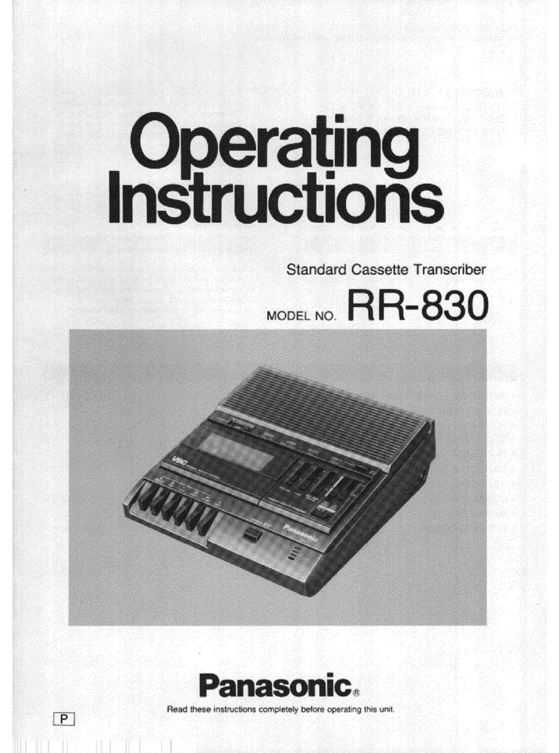
Panasonic RR830 - Desktop Cassette Transcriber User manual

Panasonic

Panasonic RR830 - Desktop Cassette Transcriber User manual

Panasonic RQ-L31 - Cassette Dictaphone User manual

Panasonic

Panasonic RQ-L31 - Cassette Dictaphone User manual

Panasonic RQL11 - CASS. RECORDER LOW User manual
Panasonic

Panasonic RQL11 - CASS. RECORDER LOW User manual

Panasonic RQ-L31 - Cassette Dictaphone User manual

Panasonic

Panasonic RQ-L31 - Cassette Dictaphone User manual

Panasonic RN-102 User manual

Panasonic

Panasonic RN-102 User manual

Panasonic RN-202 User manual

Panasonic

Panasonic RN-202 User manual
Panasonic RQ-L315 User manual

Panasonic

Panasonic RQ-L315 User manual

Panasonic RQ-S11 User manual

Panasonic

Panasonic RQ-S11 User manual

Panasonic RN-Z36 User manual

Panasonic

Panasonic RN-Z36 User manual

Panasonic RN-105D User manual

Panasonic

Panasonic RN-105D User manual

Panasonic RN-202 User manual

Panasonic

Panasonic RN-202 User manual

Panasonic RN-505 User manual

Panasonic

Panasonic RN-505 User manual
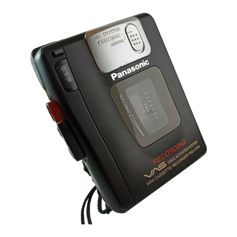
Panasonic RQ-L309 User manual

Panasonic

Panasonic RQ-L309 User manual

Panasonic RQ-L50 User manual

Panasonic

Panasonic RQ-L50 User manual

Panasonic RQ-L30 User manual

Panasonic

Panasonic RQ-L30 User manual

Panasonic RQ-L31 - Cassette Dictaphone User manual

Panasonic

Panasonic RQ-L31 - Cassette Dictaphone User manual

Panasonic RN-102 User manual

Panasonic

Panasonic RN-102 User manual

Panasonic RN-505 User manual

Panasonic

Panasonic RN-505 User manual

Panasonic RQ-L349 User manual

Panasonic

Panasonic RQ-L349 User manual

Panasonic RN-190 User manual

Panasonic

Panasonic RN-190 User manual

Panasonic RQ-SX44 User manual

Panasonic

Panasonic RQ-SX44 User manual
Popular Microcassette Recorder manuals by other brands
Grundig DH 2028 manual

Grundig

Grundig DH 2028 manual

Radio Shack Micro-44 owner's manual

Radio Shack

Radio Shack Micro-44 owner's manual

Aiwa M-185 Service manual

Aiwa

Aiwa M-185 Service manual

Aiwa TP-M340 Service manual

Aiwa

Aiwa TP-M340 Service manual

Sony M-425 operating instructions

Sony

Sony M-425 operating instructions

Aiwa TP-M145 operating instructions

Aiwa

Aiwa TP-M145 operating instructions

Tiger 83-506 operating instructions

Tiger

Tiger 83-506 operating instructions

Memorex MB2186A - MB Microcassette Dictaphone user guide

Memorex

Memorex MB2186A - MB Microcassette Dictaphone user guide

Sony M-455 - Microcassette Recorder operating instructions
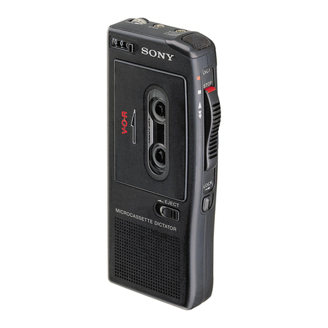
Sony

Sony M-455 - Microcassette Recorder operating instructions

ION TAPE2PC Quick start manual

ION

ION TAPE2PC Quick start manual

Sony Walkman TCD-D100 Specifications

Sony

Sony Walkman TCD-D100 Specifications

Sony ICD-SX operating instructions

Sony

Sony ICD-SX operating instructions

manuals.online logo
manuals.online logoBrands
  • About & Mission
  • Contact us
  • Privacy Policy
  • Terms and Conditions

Copyright 2025 Manuals.Online. All Rights Reserved.