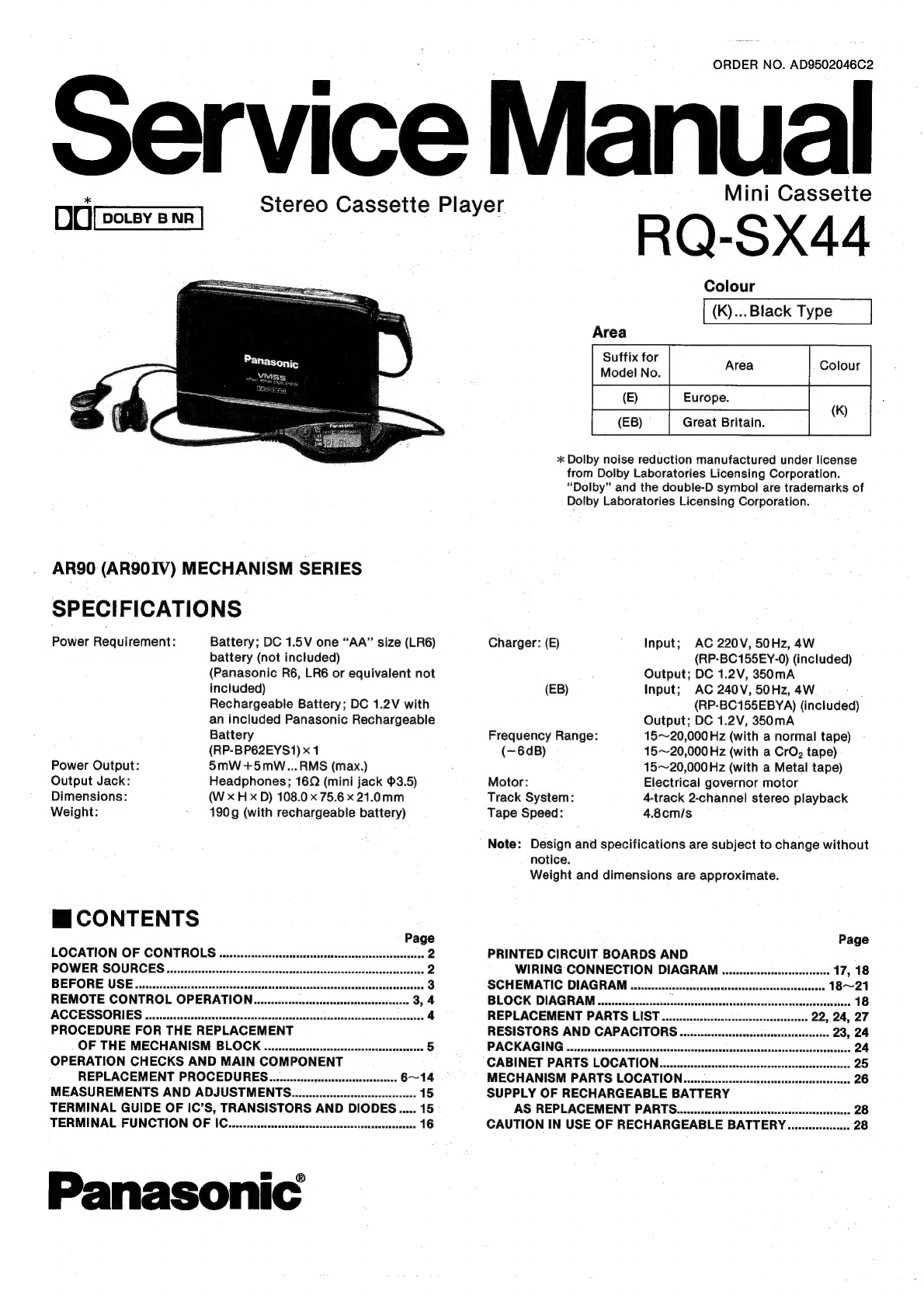
Panasonic RQ-SX44 User manual
Other Panasonic Microcassette Recorder manuals

Panasonic
Panasonic RN-505 User manual

Panasonic
Panasonic RQ-L31 - Cassette Dictaphone User manual

Panasonic
Panasonic RQ-L309 User manual

Panasonic
Panasonic RQL11 - CASS. RECORDER LOW User manual

Panasonic
Panasonic RQ-330 User manual

Panasonic
Panasonic RQ-L31 - Cassette Dictaphone User manual

Panasonic
Panasonic RN-505 User manual

Panasonic
Panasonic RQ-S11 User manual

Panasonic
Panasonic RQ-L349 User manual

Panasonic
Panasonic AK95 User manual

Panasonic
Panasonic RQ-L30 User manual

Panasonic
Panasonic RQ-L309 User manual

Panasonic
Panasonic transcriber - RR 930 Microcassette User manual

Panasonic
Panasonic RN-102 User manual

Panasonic
Panasonic RQ-L31 - Cassette Dictaphone User manual

Panasonic
Panasonic RN-202 User manual

Panasonic
Panasonic RQ-L31 - Cassette Dictaphone User manual

Panasonic
Panasonic RN-105D User manual

Panasonic
Panasonic RN-202 User manual

Panasonic
Panasonic RN-102 User manual


Popular Microcassette Recorder manuals by other brands


Sony
Sony M-430 - Microcassette Recorder operating instructions

Sony
Sony BM-575 operating instructions

Memorex
Memorex MB2186A - MB Microcassette Dictaphone Specifications

Sony
Sony M - 475 operating instructions

Sony
Sony RS-DAT-700 Supplemental operating instructions

Radio Shack
Radio Shack MICRO-36 owner's manual