1 CONTROL PANEL 4
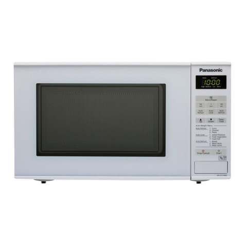
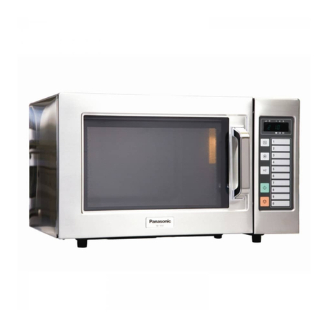
1.1. NE-1027 4
1.2. NE-1037 5
2 OPERATION PROCEDURE 6
2.1. Manual Heating for Single Stage 6
2.2. Manual Heating for 2nd Stage 6
2.3. Memory Setting for Single Stage Operation Oven is not in
program lock mode. 6
2.4. Memory setting for 2nd stage 7
2.5. Memory Pad Heating 7
2.6. To Read Cycle Counter 8
2.7. To Select Beep Tone Options (ON/OFF of Beep Tone) 8
2.8. To Lock Program of Memory Pad 8
2.9. To Release the Memory Pad Program Lock 8
3 SCHEMATIC DIAGRAM 9
3.1. NE-1027 9
3.2. NE-1037 10
4 DESCRIPTION OF OPERATING SEQUENCE 11
4.1. Variable power cooking control (NE-1027) 11
4.2. Variable power cooking control (NE-1037) 11
5 CAUTIONS TO BE OBSERVED WHEN TROUBLESHOOTING
12
5.1. Check the earthing 12
5.2. If the door lock, the door switch, the door seal or the door
develops a malfunction, be sure not to operate the oven
until complete repairs are made. 12
5.3. Warning about the electric charge in the high voltage
capacitor 12
5.4. When parts must be replaced, remove the power plug
from the outlet. 13
5.5. When the 10 Amp/2.5 Amp fuse is blown due to the
operation of short switch: 13
5.6. Avoid inserting nails, wire, etc. through any holes in the
unit during operation. 13
5.7. Confirm after repair 13
6 DISASSEMBLY AND PARTS REPLACEMENT PROCEDURE
14
6.1. Magnetron 14
6.2. Digital Programmer Circuit (D.P.C.) and membrane
keyboard. (NE-1037) 14
6.3. Low voltage transformer and/or power relays (RY1, RY2,
RY3, RY4) (NE-1037) 15
6.4. Fan motor 15
6.5. Stirrer motor 15
6.6. Door assembly 16
6.7. Temp sensor (thermal protector) (NE-1037) 16
6.8. Floor shelf and/or moving antenna 16
7 COMPONENT TEST PROCEDURE 17
7.1. Primary Latch Switch, (Door Switch and Power Relay B)
Interlocks. 17
7.2. Short Switch & Monitor 17
7.3. High voltage transformer 17
7.4. High voltage capacitor 17
7.5. Magnetron 17
7.6. Variable power controller (NE-1027) 18
7.7. Diode 18
7.8. Protector diode 18
7.9. Membrane key board (Membrane switch assembly)(NE-
1037) 18
7.10. Temp sensor (Thermal protector) (NE-1037) 18
8 MEASUREMENTS AND ADJUSTMENTS 19
8.1. Adjustment of Safety switch A, Safety switch B and short
switch 19
8.2. Measurement of microwave output 19
9 TROUBLESHOOTING GUIDE 20
9.1. NE-1027 20
9.2. NE-1037 22
10 EXPLODED VIEW AND PARTS LIST 26
10.1. EXPLODED VIEW 26
10.2. PARTS LIST 27
10.3. DOOR ASSEMBLY 28
10.4. ESCUTCHEON BASE ASSEMBLY 29
10.5. PACKING AND ACCESSORIES 31
10.6. WIRING MATERIALS 32
11 DIGITAL PROGRAMMER CIRCUIT (NE-1037) 33
11.1. SCHEMATIC DIAGRAM 33
CONTENTS
Page Page
3
NE-1027 / NE-1037
